
Abstract
Mechanism of chip formation during dry machining of Ni-based super alloys needs considerable research attention as it directly or indirectly affects different aspects of machinability. Therefore, the present research work aims at understanding the mechanism of chip formation with the help of various chip characteristics during dry machining of Inconel 825, a nickel-based super alloy. The influence of multilayer coating deposited using chemical vapour deposition, cutting speed and machining duration has been investigated on types and form of chips, along with different characteristics of chip like shear band thickness, saw-tooth distance, equivalent chip thickness, saw-tooth angle and chip segmentation frequency. Chip–tool contact length, hardness and crystallographic orientation (through X-ray diffraction) of chip have also been studied. Furthermore, different machining characteristics such as cutting force, apparent coefficient of friction and cutting temperature have also been determined for explaining the mechanism of various aspects of chip formation. The results indicated that coated tool restricted sharp increase in shear band thickness with cutting speed and resulted in reduction in saw-tooth distance, saw-tooth angle, equivalent chip thickness, chip hardness and deformation on grains while exhibiting increase in chip segmentation frequency in comparison with its uncoated counterpart.
Introduction
Formation of chips plays a pivotal role in the research in machining as it has close interrelationship with cutting force, temperature, machined surface roughness, tool wear, and so on. Considerable research work has been undertaken to study various aspects of chip characteristics considering different workpiece material, with particular emphasis on different grades of steel. However, there still exists lack of complete agreement on basic mechanism of chip formation and its correlation with cutting parameters. Formation of shear band occurs due to thermoplastic instability when the rate of thermal softening exceeds the rate of strain hardening.1–5 This shear band is responsible for generation of segmented or serrated (also known as shear localised) chips during machining of workpiece materials such as titanium and nickel-based super alloys having low thermal conductivity or those with elevated strength like hardened steel. 3 Shear band is an important aspect of chip characteristics as it may also cause fluctuation of cutting force.1–7 Both the phenomena of thermal softening and strain hardening responsible for segmented chips depend heavily on cutting parameters, thermo-mechanical properties of workpiece and cutting tool.
The chip morphology during machining is not only dependent on tool materials and cutting parameters, but other factors like grain size hardness of the workpiece material, use of coolant and geometry have significance influence on types of chips.8–14 Moreover, greater work hardening difference between deformed surface and undeformed surface of the work material in machining results in small undeformed chip thickness, which may cause problem during the machining. 13
Chip morphology is also influenced by the type of tool coatings which are conventionally deposited using physical vapour deposition (PVD) and chemical vapour deposition (CVD). The chip serration was more prominent when machining of Inconel 718 was carried out with PVD TiN/TiAlN coated inserts compared to that when using CVD coated TiN/Al2O3/TiCN carbide tool. This was attributed to the stronger metallurgical bond of CVD coating with cutting tool substrate than that of mechanical bond in case of PVD coatings. 14 Thakur et al.15,16 demonstrated that increase in the cutting velocity resulted in decrease in chip thickness, whereas increase in the feed rate caused generation of thicker chips but with reduction in chip compression ratio. Similarly, increase in the chip–tool contact area also resulted in thicker chip at higher depth of cut. 16 Zhang et al. 17 investigated the influence of cutting speed parameters on types of chips and frequency of chip segmentation during machining Inconel 718. Fine and irregular type of chips were obtained at lower cutting speeds. Two important aspects of chip serration include saw-tooth distance and chip segmentation frequency. These two characteristics of serrated chip are primarily influenced by shear deformation, strain hardening and strain rate. There is no clear agreement among the trend of saw-tooth distance reported by various researchers. Kouadri et al. 18 did not find any clear trend with cutting speed. Wang et al. 19 reported increase in rise in saw-tooth distance with cutting speed, whereas the observation made by Dong et al. 8 was exactly opposite. The frequency of segmentation of saw-tooth type chip decreased with increase in cutting speed. However, the saw-tooth became more prominent under the condition of high cutting speed. The periodic fluctuation in the cutting force component could be correlated to the generation of saw-tooth type chips.7,20 Machining of Inconel 718 below cutting speed of 50 m/min resulted in generation of long and continuous chip. Segmented chips were obtained at cutting speed higher than 90 m/min. The degree of chip segmentation was more at higher velocity of 180 m/min with segments being closer than that at lower cutting velocity. 21 Saw-tooth chip angle is influenced by degree of shear deformation, strain hardening and thermal softening.20,22,23 In the feed range of 0.08–0.16 mm/rev, the spacing between chip segments increased, and thereafter, it decreased with increase in feed. Pawade et al. 24 studied the influence of cutting parameters and tool geometry on different chip formation characteristics during machining of Inconel 718. It was observed that both pitch of the serrated chip and mean height of the chips vary along the length of the chip. Cutting speed and feed were found to have pronounced influence on chip thickness ratio and hence chip morphology.
The review of the past work on chip characteristics of nickel-based super alloys clearly indicated that some study have been reported on effect of cutting parameters on types of chips, macro-morphology, chip thickness ratio and characteristics of segmented chips like saw-tooth distance, saw-tooth angle, equivalent chip thickness and chip segmentation frequency. Although different coated tools are frequently used in current industrial practice to machine difficult-to-cut workpiece materials, the potential of coated tools on overall improvement of chip characteristics during machining of Ni-based super alloys has hardly been reported. It is, therefore, essential to understand the role of coating on macro- and micro-morphology of chips and the condition leading to the formation of segmented chips. Inconel 825 is one of the Ni-based super alloys widely used in aerospace, chemical and marine industries.25–28 Although some of the machinability characteristics of Inconel 825, in particular tool wear and machined surface integrity, have recently been reported,29,30 the detailed chip characteristics of the same material under dry cutting condition are still yet to be explored. Keeping these aspects in mind, this study has been undertaken to investigate the influence of cutting speed and tool coating on micro-morphology of chips both on free surface and transverse plane, shear band thickness, equivalent chip thickness and different features of segmented chips like saw-tooth distance, saw-tooth angle, chip segmentation frequency and hardness of chip during dry machining of Inconel 825.
Materials and methods
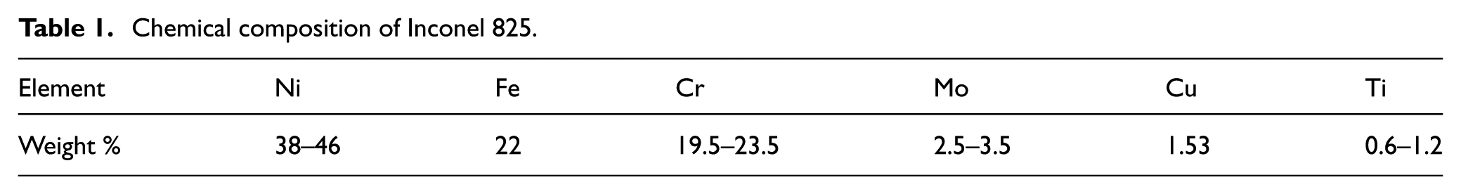
A round bar of Inconel 825 of 75 mm diameter and 300 mm length was considered as a workpiece having the chemical composition as indicated in Table 1.
Chemical composition of Inconel 825.
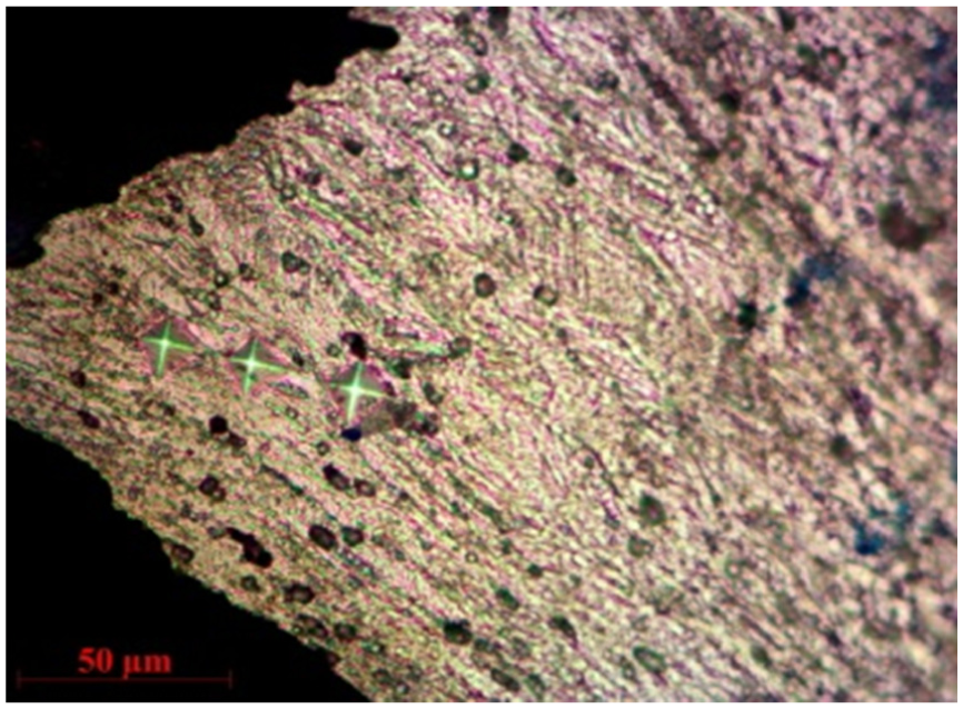
Typical microstructure of work material which is shown in Figure 1 reveals segregation of metal carbides (M23C6, where M can be Cr, Mo, Ti and Fe for Inconel 825) along the grain boundary, which is responsible for precipitation hardening characteristics of Inconel 825.27,28 Dry turning of Inconel 825 was performed in a heavy duty lathe (model: NH26; make: Hindustan machine tools (HMT) Ltd, Bangalore, India) as shown in Figure 2. The experiments were carried out with three different cutting speeds (Vc) of 51, 84 and 124 m/min along with a constant feed (f) of 0.198 mm/rev and depth of cut (ap) of 1 mm. Each experimental run was repeated thrice to check repeatability and also to improve statistical accuracy of the results. The effect of CVD multilayer coated tool having coating composition of TiN/TiCN/Al2O3/ZrCN has been investigated on different characteristics of chips during machining Inconel 825. Uncoated cemented carbide insert having ISO P30 grade has also been used for comparative evaluation. The designations of tool and tool holder for both uncoated and coated inserts were ISO SCMT120408 and SSBCR2020K12, respectively. The uncoated and coated tools were supplied by Widia, India, whereas the tool holder was procured from Kennametal, India.
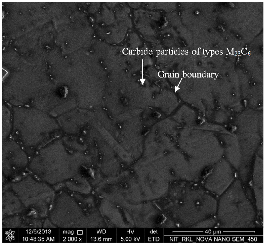
SEM image of microstructure of Inconel 825.
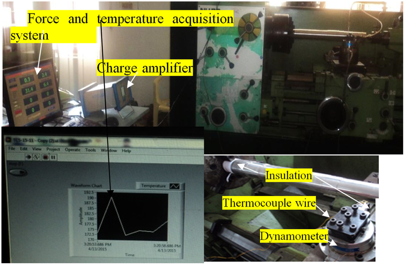
Photograph of the experimental setup for turning Inconel 825.
After each experimental run, chip was collected for further analysis. Macro-morphology of the chip was studied using a stereo zoom microscope (make: Radical Instruments). Cutting force was measured using four-component piezoelectric dynamometer (model: 9272; make: Kistler, Switzerland) in combination with a charge amplifier (model: 5070A10100; make: Kistler Instrumente AG, CH-8408 Winterthur, Switzerland). A tool-work thermocouple (K-type) was used to approximately measure cutting temperature. This technique is one of the simplest as well as widely accepted methodologies to measure cutting zone temperature.28,31,32 For measuring temperature, the probe having diameter of 0.5 mm was placed at the interface of insert and shim at the place at a distance 4 mm below tool tip. Proper insulation was provided (Teflon tape) for reducing heat transfer on the head stock, tail stock and tool holder. Micro-morphology of the chips involving both free and under surfaces was investigated using scanning electron microscopy (SEM) (make: NOVA NANO SEM-450) in combination with energy dispersive spectroscopy (EDS) through X-ray for analysing wear debris. For studying the different characteristics of serrated chips, test specimens were prepared by embedding the chips inside epoxy resin moulds (cold mounting). The specimens were initially polished with different grades of polishing paper having SiC grits with decreasing size. Final surface finish was obtained by polishing with diamond paste before etching. The polished surfaces were then etched with 2% (by volume) of diluted (40%) hydrofluoric acid, 40% of concentrated hydrochloric acid, 50% of de-ionised water and 8% hydrogen peroxide. The micro-features of the chip’s cross section were studied using AxioCam ERc 5s optical microscope (make: Carl Zeiss) coupled with digital image processing software (AxioVision, release 4.8.2). Hardness of the chip samples was measured on the transverse plane using a Vickers microhardness tester (make: LECO, USA) with 100 g load.
Results and discussion
Cutting force and temperature
Cutting force and temperature play some major role in chip formation of nickel-based super alloys during machining, since past literature has clearly established the significance of plastic deformation and thermal softening in chip formation. Variation of cutting force and temperature with machining duration has been shown in Figure 3. Relation between cutting speed and force could be related to tool wear. While the tools were fresh, cutting speed hardly impacted cutting force. With the progress of machining, when tool wear was very much prominent for the uncoated tool, cutting force consistently exhibited rising trend with cutting speed. For the coated tool, there was no noticeable difference in cutting force for the cutting speeds of 51 and 84 m/min due to its capability to successfully restrict tool wear. Except at the beginning of the cut using coated tool, cutting force was always higher, in the range of 3%–7%, for the cutting speed of 124 m/min when compared to lower cutting speeds. On the other hand, continuously increasing trend is noted for cutting temperature with cutting speed as well as machining duration. Cutting force under lower cutting speed of 51 m/min was almost similar for both uncoated and coated tools, since the tool coating was perhaps not capable enough to get rid of the high frictional drag force under lower cutting speed. However, remarkable reduction in cutting force with TiN/TiCN/Al2O3/ZrCN coated tool under higher cutting speeds (84 and 124 m/min) might be attributed to its anti-friction properties, higher hardness and thermal stability compared to its uncoated counterpart. However, the same coated tool resulted in higher temperature which was possibly due to low thermal conductivity of Al2O3 that restricted the heat intake into the coated tool and protect the tool substrate (WC). However, it is also the high thermal stability of Al2O3 coating which might be responsible for the improved performance of the coated tool.
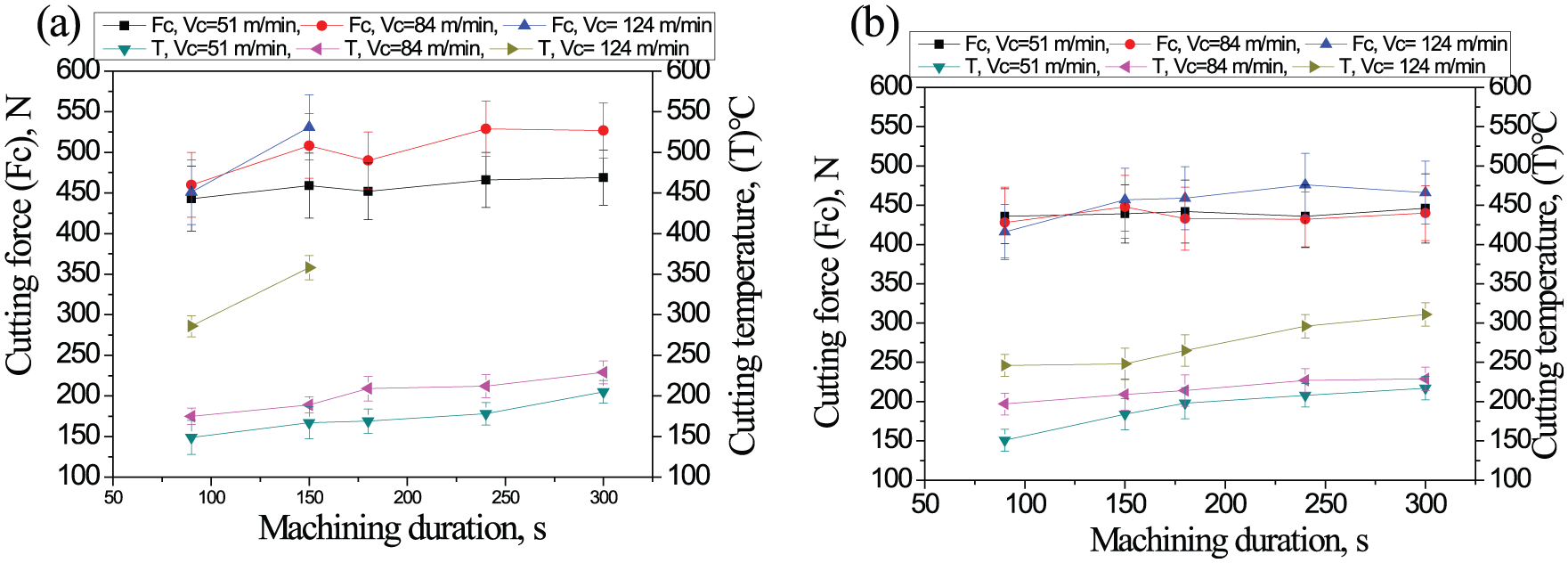
Variation of cutting force and temperature with machining duration and cutting speed during machining of Inconel 825 using (a) uncoated and (b) coated carbide inserts.
Apparent coefficient of friction
Apparent coefficient of friction at chip–tool interface is governed by built-up edge (BUE) as well as tool wear. The value of apparent coefficient of friction has been calculated by equations (1)27,33 and (2) and subsequently plotted against machining duration using uncoated and coated tools in Figure 4

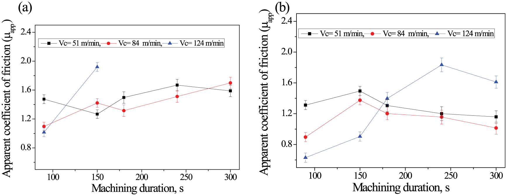
Variation of apparent coefficient of friction with machining duration and cutting speed during machining of Inconel 825 using (a) uncoated and (b) coated carbide inserts.
where γ is the orthogonal rake angle with a value of 6°

where Ft is thrust force.
Multilayer coated tool has an ability to reduce friction in comparison with the uncoated one due to anti-friction property of different components such as TiN and ZrCN. It is interesting to note that friction could be reduced at elevated cutting speed for both uncoated and coated tools. However, there was a reversal in trend with progression of machining primarily due to tool wear. Increasing trend of chip–tool interface friction which is evident for the coated tool under high cutting speed (124 m/min) might be attributed to partial removal of coating with progression of machining. 34
Orientation of shear band in chip
Although chip formation mechanism of nickel-based super alloy like Inconel 718 has been studied, it would be also interesting to investigate the same for other grades having different thermo-mechanical properties. 35 Representative optical microscopic images of segmented chips of Inconel 825 along with shear band obtained with uncoated and coated tools are indicated in Figures 5(a) and (b). Micro-fracture at the tip might be related to strain hardening tendency of Inconel 825. Figure 6 represents the variation of shear band thickness with cutting speed using uncoated and coated tools during machining of Inconel 825. Gradual increase in shear band thickness is revealed with cutting speed for both the tools. Such a trend of variation with cutting speed can be explained by higher degree of thermal softening. Steep increase in shear band thickness with cutting speed for uncoated tool is ascribed to escalation in cutting temperature as shown in Figure 3, and consequently thermal softening. On the other hand, smaller slope of curve for the coated tool can be explained by mechanical deformation leading to dynamic recrystallization particularly at high cutting speed. 29 More severe shear localisation is caused by poorer thermal conductivity of workpiece material due to higher heat accumulation in narrow zone (shear band) and also by high resistance to deformation of individual chip segments. From Figure 7, it is evident that Inconel 718 has poorer thermal conductivity as well as higher strength than Inconel 825 in the temperature range typically encountered during machining. Comparing the mechanism of chip formation of Inconel 718 with that of Inconel 825 under similar cutting speed, it is evident that more intense shear localisation can be expected in Inconel 718. As a result, chip segments of Inconel 718 have greater tendency to separate along the shear band at relatively lower cutting speed of 122 m/min as evident from Figure5(c). 3 Interestingly, such tendency could not be observed with Inconel 825 under similar cutting condition (Vc = 124 m/min and f = 0.2 mm/rev), although serrated teeth of the chips got deeper with elevation in cutting speed (Figure 5(b)). Therefore, it may be inferred that isolation of chip segments would be expected at higher cutting speed for Inconel 825 in comparison with Inconel 718.
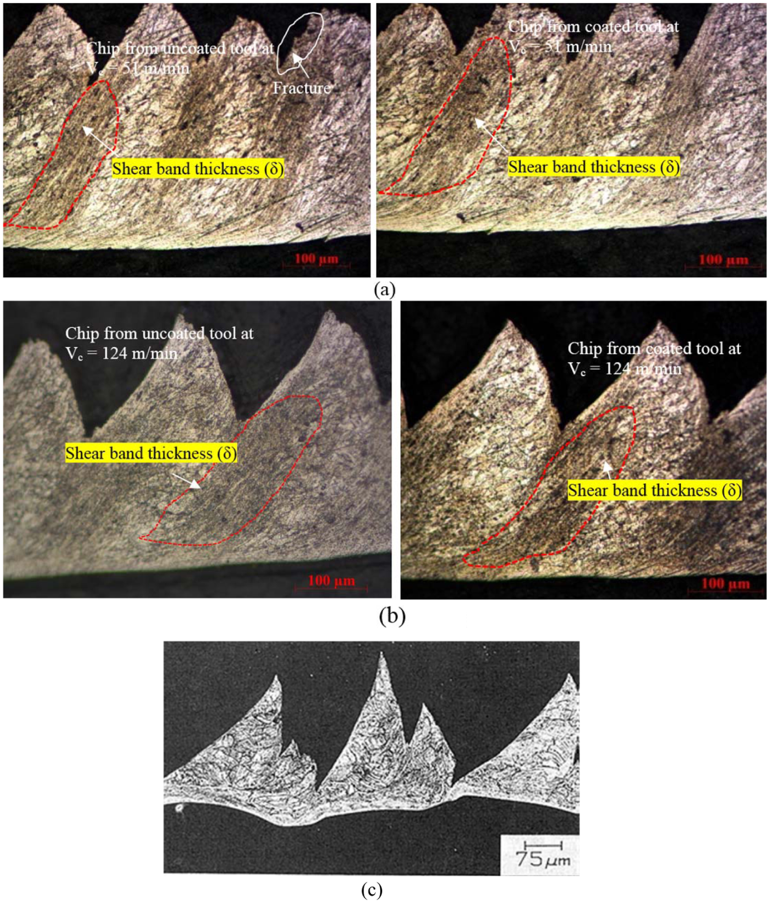
Representative optical images of cross section of chip showing shear band thickness during machining of Inconel 825 uncoated and coated carbide inserts at Vc of (a) 51 and (b) 124 m/min, and (c) optical micrographs of the Inconel 718 chip obtained at 122 m/min, where the extent of contact between the segments has been drastically reduced due to extensive shear between the segments. 3
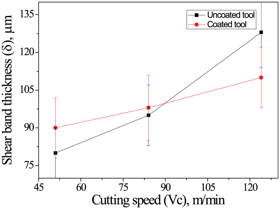
Variation of shear band thickness with cutting speeds during machining of Inconel 825 using uncoated and coated carbide inserts.
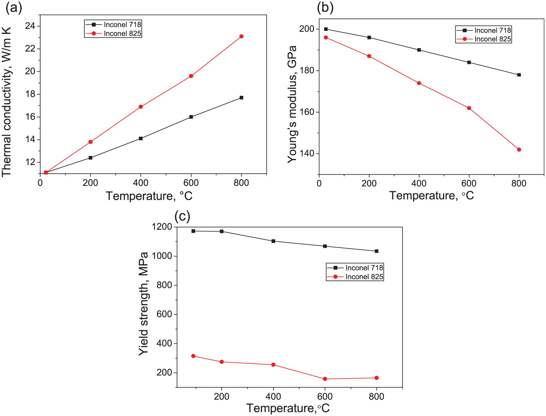
Comparison of material properties (a) thermal conductivity, (b) Young’s modulus and (c) yield strength of Inconel 718 and Inconel 825 as functions of temperature. 3
Influence of cutting condition on characteristics of saw-tooth chip
Study of micro-morphology of chips
Formation of serrated chip during machining of nickel-based super alloys occurs due to shear localisation in primary deformation zone. Cutting speed plays an important role in deciding whether thermal softening or strain hardening would govern mechanism of chip formation during machining nickel-based super alloys. A representative SEM image of the cross section of a serrated chip revealing various characteristics of chip serrations obtained after machining Inconel 825 has been indicated in Figure 8. The various features include maximum thickness of saw-tooth chip (H), continuous part of the serrated chip (h), saw-tooth distance (Pc) and saw-tooth angle (Φ1) as indicated in Figure 8. Additionally, some material adhered on the back surface of the chips has been noticed. EDS point analysis reveals that wear debris primarily consists of adhered work material on rake face (BUE) with minor trace of tungsten from cutting tool. Such re-deposited material can be subsequently transferred to the machined surface, thus deteriorating surface integrity.
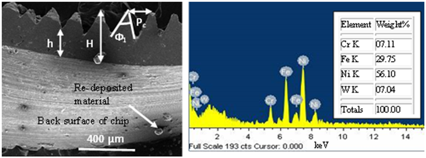
Representative SEM image of chip showing different features along with EDS spectrum of re-deposited material.
Figure 9 shows SEM images of free surface and corresponding optical images of the cross section of chip depicting gradual transformation with the progression of machining using both uncoated and CVD multilayer coated tool at different cutting speeds. Different features of free surface of the chips can be detected from the SEM images. Primary serrated teeth, as indicated in Figure 9, result from primary shear deformation, whereas secondary serrated teeth are generated at the corner of chip due to side flow of material, that is, secondary deformation. SEM micrographs also depict undeformed and slipping surfaces of the serrated chips.7,36 It is quite evident from the figure that cutting speed, machining duration and tool coating do have some influence on the chip morphology and characteristics of chip serration. Difference in sharpness of segment of the tip has also been noted. Roundness is the result of upsetting of developing segment of chips prior to catastrophic failure, whereas segment becomes more pointed for harder materials and also when cutting speed is increased. 37 General trend in the current work also indicates sharpening of tips with increase in cutting speed particularly for coated tool, whereas prominent tool wear for its uncoated counterpart leads to rounding of tips. It is evident from the same figure that chips with truncated saw-tooth profile were obtained at lower cutting speed (51 m/min), particularly with the progression of machining. This can be explained by higher chip–tool interface friction at lower cutting speed while using uncoated tool. Degree of deformation of chip as well as tool wear increased with machining duration, leading to gradual flattening of saw-tooth. Both of these aspects could be improved with the application of coated tool as evident from the same figure.
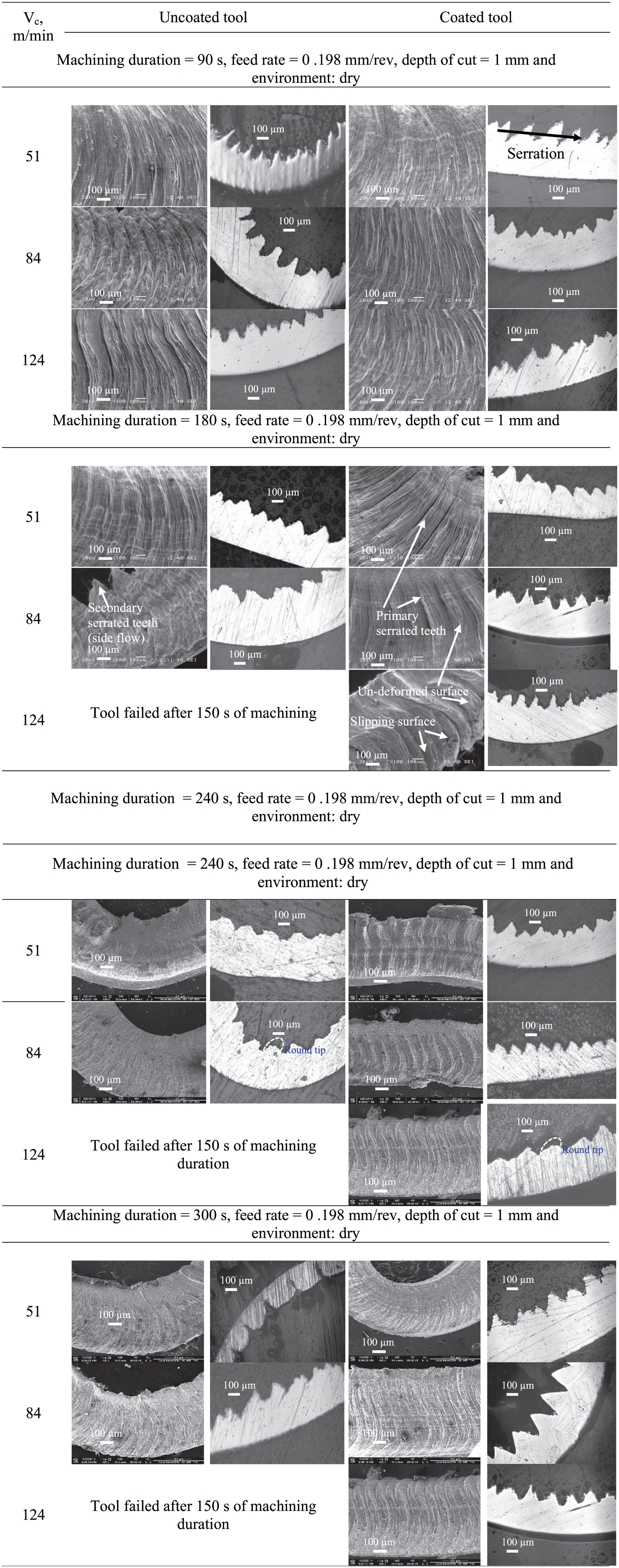
SEM images and corresponding optical images of chips with machining duration and cutting speeds using uncoated and coated tools.
From Figure 8, various characteristics of chip serration such as saw-tooth distance, equivalent chip thickness, saw-tooth angle and chip segmentation frequency have been calculated and analysed.
Saw-tooth distance (Pc) and chip segmentation frequency (fch)
Saw-tooth distance was calculated from the micro-morphology of the chips, whereas frequency of chip segmentation was calculated from equation (3) 8

Variation of the saw-tooth distance in this study has been shown in Figure 10. Increase in saw-tooth distance with cutting speed or machining duration may be attributed to the degree of deformation (strain rate) as well as tool wear, where fall can be explained by the effect of thermal softening. Since coated tool has the capability to restrict degree of deformation which in turn leads to less flank wear, saw-tooth distance could be reduced with the use of coated tool. Most prominent decrease could be noted at medium cutting speed. Since both the effects of strain hardening or thermal softening are less dominant at low cutting speed (as can be noticed from Figure 3) compared to those at medium and high cutting speed, coated tool did not cause substantial reduction in saw-tooth distance. Under high cutting speed, uncoated tool failed after 150 s of machining and therefore was discontinued. 26 Steady increase in saw-tooth distance for coated tool at high cutting speed was due to increase in flank wear and increase in degree of deformation or strain hardening.
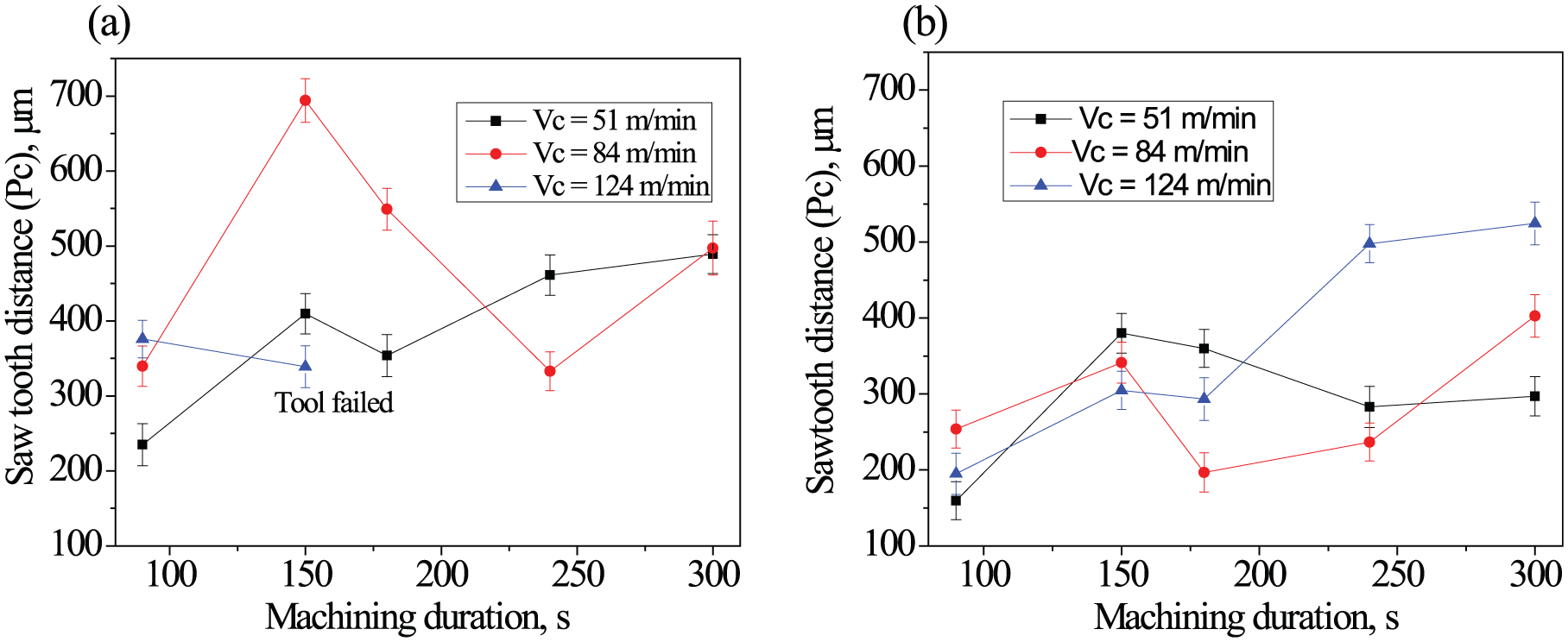
Variation of saw-tooth distance with machining duration and cutting speed during machining of Inconel 825 using (a) uncoated and (b) multilayer coated carbide inserts.
Figure 11 depicts the effect of cutting speed, machining duration and CVD multilayer coated carbide tool on chip segmentation frequency. Chip segmentation frequency is dictated by two competing phenomena, namely, strain hardening or degree of deformation and thermal softening. The figure clearly reveals that increase in chip segmentation frequency with cutting speed took place for the fresh tools, both uncoated and coated. Moreover, the same for coated tool was significantly more than its uncoated counterpart. Increase in chip segmentation frequency might be related to reduction in chip–tool interface friction (Figure 4), rise in cutting temperature and improvement in overall machinability associated with enhanced cutting speed (resulting in rise in cutting temperature and consequent material softening) and with the application of coated tool. Tool wear plays a major role in decreasing chip segmentation frequency. Tool wear causes plastic deformation in the primary shear zone to be more and causes large variation in cutting force. A further increase in the flank wear leads to intensification of the chip segmentation. Plastic deformation of the material in the primary cutting zone becomes more pronounced with a distinctive border between the formed segments. The current work, in addition to bolstering their claims, showed an interesting feature of increase in chip segmentation frequency with coated tool by virtue of reduced flank wear. A separate study of the authors indicated that multilayer coated tool restricted tool wear significantly during dry machining of Inconel 825 at high cutting speed, that is, 124 m/min. 26 Therefore, coated tool has caused higher chip segmentation frequency. It is interesting to note that the degree of increase also expanded when the cutting speed was elevated from 51 to 124 m/min. This is due to the higher effectiveness of the coated tool in augmenting resistance to wear at high cutting speed compared to that at lower cutting speed. No consistent trend of variation of chip segmentation frequency with machining duration could be revealed.
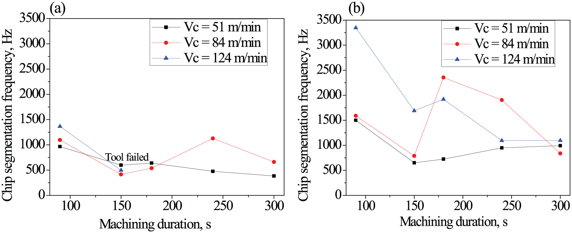
Variation of chip segmentation frequency with machining duration and cutting speed during machining of Inconel 825 using (a) uncoated and (b) multilayer coated carbide inserts.
Equivalent chip thickness (hch)
Another important characteristic of serrated chip is equivalent chip thickness which is expressed by equation (4) 19

Increase in cutting speed led to decrease in equivalent chip thickness for uncoated tool (except at the initial condition), as evident from Figure 12, owing to increase in flow velocity and consequent reduction in tendency in chip stagnation over rake surface of the tool and reduction in cutting force (Figure 3). On the other hand, there is no uniform trend of variation of hch with Vc for coated tool. If behaviour of the coated tool is taken into consideration, as such the trend is not very consistent with machining duration. However, at the beginning (i.e. after 60 s of machining), values were same for the coated tool irrespective of cutting speed. Variation of hch typically depends on chip–tool interface friction, fluctuation of force and tool wear. Since none of these effects is predominant for the fresh coated tool, cutting speed hardly has any impact on hch. Increase in hch till 150 s, followed by reduction, may be attributed to the formation and subsequent removal of BUE and edge rounding due to tool wear. Higher edge rounding would tend to decrease effective deformed layer thickness and consequently result in lower chip thickness. Increasing trend of equivalent chip thickness for the coated tool under high cutting speed can be explained by higher chip–tool interface friction and tool wear due to partial removal of coating. 26 However, there is always a drooping nature of the curve towards the end, that is, after 240 s of machining. Interestingly, due to the same explanation, drooping nature of chip segmentation frequency (Figure 11) and increasing trend of equivalent chip thickness (Figure 12) seemed to be correlated.
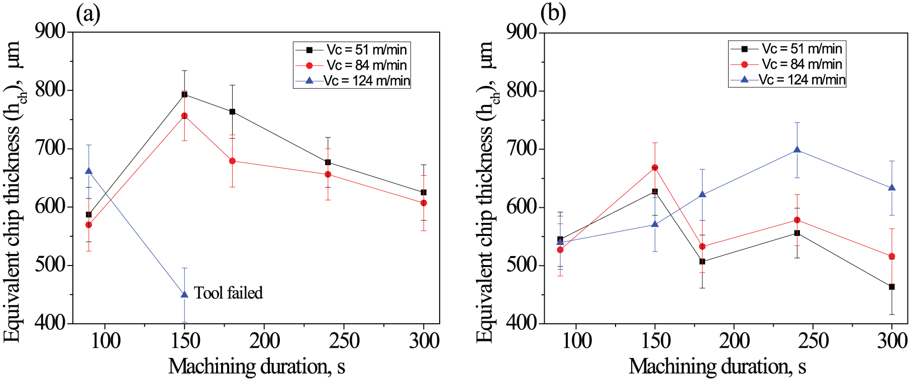
Variation of the equivalent chip thickness with progression of machining and cutting speeds during dry machining of Inconel 825 using (a) uncoated and (b) multilayer coated carbide inserts.
Saw-tooth chip angle (Φ1)
The trend of variation of the saw-tooth chip angle with cutting speed and machining duration is dictated in Figure 13 by the competitive influence of these mechanisms which is difficult to predict. It is evident that rise in cutting speed causes Φ1 to increase (except for two machining durations of 150 and 180 s while using coated tool), which is primarily related to higher rate of deformation. Interestingly, increase in cutting temperature resulting from elevation in cutting speed and machining duration can lead to both thermal softening as well as strengthening of work material in the form of dynamic recrystallization with or without grain growth. 29 Accordingly, decreasing trend of Φ1 is related to thermal softening, whereas increasing trend can be explained by strain hardening for both uncoated and coated tools. 38 General increasing trend after 180 s of machining with the coated tool can, therefore, be explained by thermal softening due to prominent increase in temperature caused both by deformation as well as tool wear.29,34
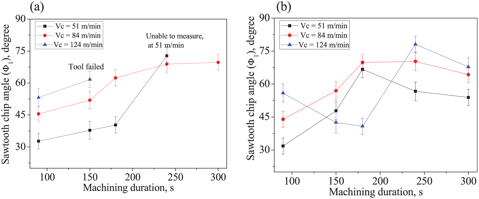
Variation of saw-tooth chip angle with machining duration and cutting speeds during dry machining of Inconel 825 using (a) uncoated and (b) multilayer coated carbide inserts.
Study of chip–tool contact length (Lch)
Chip–tool contact length is one of the important aspects deciding the mechanism of chip formation during machining. This has been measured from the SEM micrographs of the rake surface of the tool as shown in representative SEM image in Figure 14. Figure 15 represents variation of chip–tool contact length with progression of machining and cutting speed when machining was carried out with both uncoated and coated tools. It is evident from the figure that chip–tool contact length gradually decreased with machining duration till 240 s and subsequently increased when machining with cutting speeds of 51 and 84 m/min. Decrease in chip–tool contact length with elevation in cutting speed was observed. 18 Chip–tool contact length is primarily governed by chip–tool interface friction and tool wear. The observed phenomena might be attributed to the initial formation of built-up layer (BUL) or BUE which got reduced as the machining operation progressed. After a machining duration of 240 s, the role of tool wear became more predominant which led to rise in contact length. The figure also clearly demonstrated two more aspects with relation to chip–tool contact length. Increase in cutting speed for both uncoated and coated tools resulted in reduction in contact length except for high cutting speed for uncoated insert. Coated tool was found to be beneficial in reducing chip–tool contact length during dry machining of Inconel 825. Application of high cutting speed or use of coated tool contributed to a reduction in chip–tool interface friction (Figure 4) resulting in decrease in chip–tool contact length. However, tool wear played a predominant role at high cutting speed (124 m/min) for uncoated tool, leading to rapid increase in contact length.
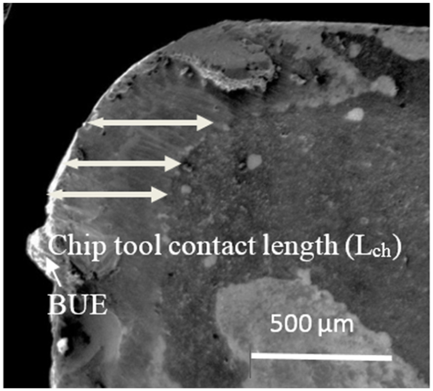
Representative SEM image of rake surface indicating measurement of chip–tool contact length.
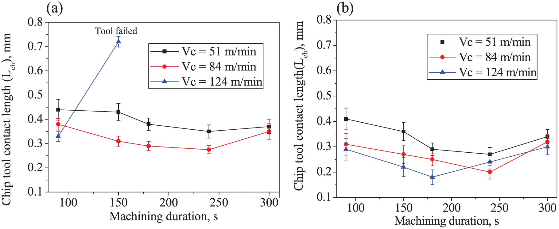
Variation of chip–tool contact length with machining duration and cutting speeds during dry machining of Inconel 825 using (a) uncoated and (b) multilayer coated carbide inserts.
Microhardness of chip
Microhardness of chip is primarily influenced by deformation due to thermal softening and deformation due to shear strain.31,39 Measurement of microhardness was carried out in the matrix of chips as shown in Figure 16 obtained under different machining conditions. Variation of chip hardness with progression of machining duration for different cutting speeds using both uncoated and CVD coated insert is shown in Figure 17. It clearly indicates that there was a rise in microhardness of chip with increase in cutting speed which might be attributed to mechanical deformation associated with high cutting speed. With increase in cutting speed, combination of both mechanical and thermal deformation results in increase in dislocation density, thereby causing grain refinement. 29 This might be responsible for increase in microhardness of chip during machining. As such, when machining was carried out progressively, there was hardly any uniform variation of microhardness of chip with machining duration. However, increase in microhardness is attributed to mechanically induced deformation leading to dynamic recrystallization. On the other hand, thermally induced deformation leads to material softening. These two competing mechanisms are essentially responsible for the variation of results. Application of multilayer coating appeared to bring down chip hardness particularly at low and medium cutting speeds. Beneficial effect of coating in reducing chip microhardness may be explained by decrease in strain hardening. This result is in good agreement with influence of tool coating on saw-tooth distance (Figure 10). Decrease in work hardening of the machined surface causes improvement of surface integrity with the application of the same coated tool.29,39
Representative optical image of microhardness indentation on matrix of chip.
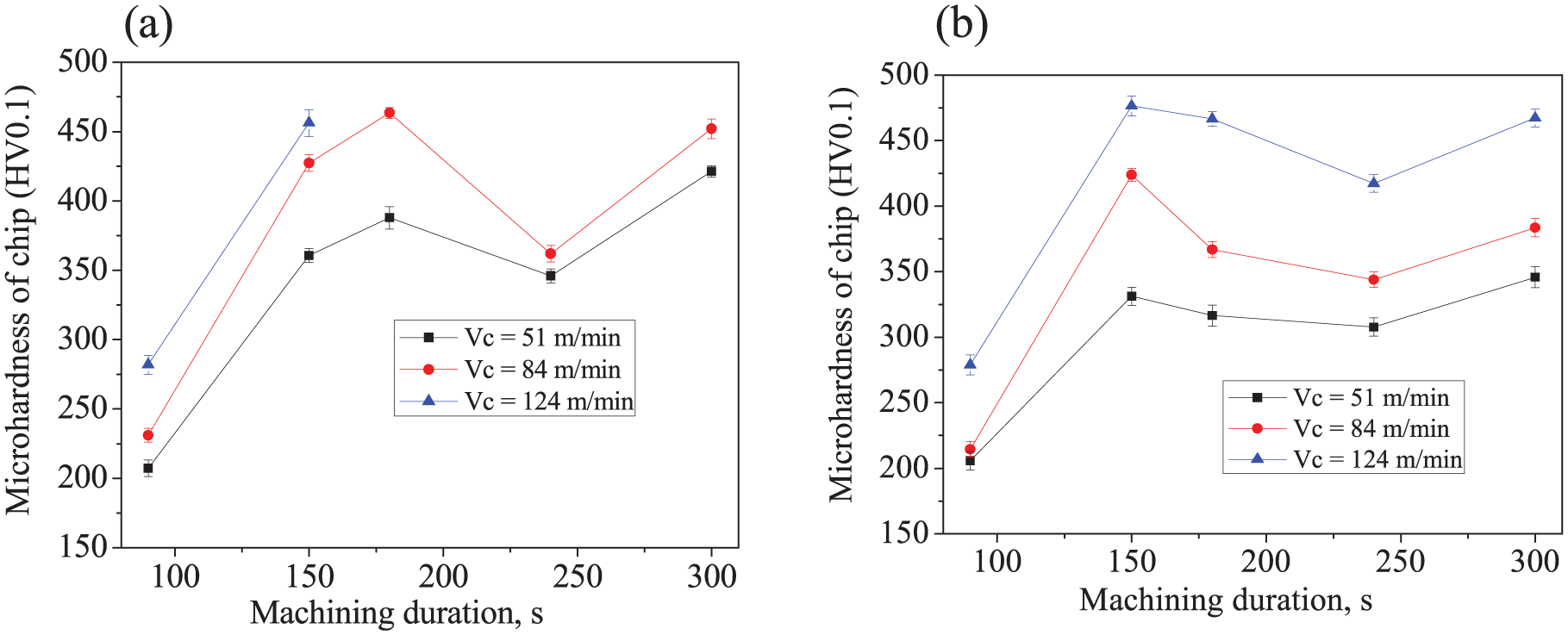
Variation of microhardness of chip measured at the matrix of chip with machining duration and cutting speed during dry machining of Inconel 825 using (a) uncoated and (b) multilayer coated carbide inserts.
X-ray diffraction of chip
X-ray diffraction (XRD) was carried out on chips obtained with uncoated and multilayer coated tools to investigate whether there was any phase transformation, modification of grain size or lattice strain. Figure 18(a) indicates XRD spectra of chips obtained during turning of Inconel 825 with cutting speed of 84 m/min using both uncoated and multilayer coated tools. The figure reveals there was neither significant change in phase nor prominent shifting of peaks in the deformed chips due to application of coated tool. On the other hand, uncoated tool effected noticeable broadening of peaks, indicating that grain size of the chips obtained with the uncoated tool was less compared to its coated counterpart. The result is indicative of higher amount of plastic deformation and chip–tool interface friction, 39 resulting in strain hardening taking place during machining with uncoated cemented carbide insert which could be reduced with the application of coated tool. It is known that peak broadening, that is, increase in full-width half maxima (FWHM), is related to grain refinement and shown in Figure 18(b), which in turn is responsible for rise in hardness according to Hall–Petch effect. 40 The XRD result can therefore explain the harder chip obtained with uncoated tool in comparison with the coated one while machining with a cutting speed of 84 m/min.
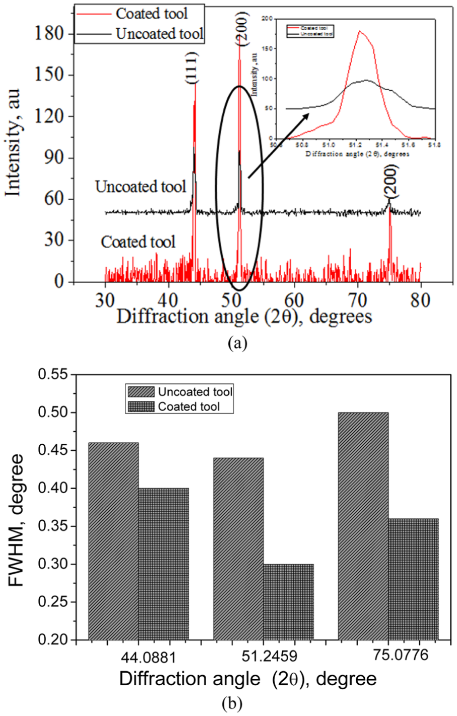
Variation of (a) spectra of X-ray diffraction and (b) FWHM of chip after dry turning of Inconel 825 using uncoated and multilayer coated inserts.
Conclusion
The present study aimed at investigating the influence of cutting speed, multilayer coated tool, as well as machining duration on different characteristics of chip during dry turning of Inconel 825. The research work resulted in the following conclusions:
Cutting force and apparent coefficient of friction obtained with uncoated tool could be significantly reduced with the coated tool under medium (84 m/min) and high (124 m/min) cutting speeds, which however resulted in higher cutting temperature except under high cutting speed.
Shear localisation in the chips of Inconel 825 was evidently less severe compared to that for Inconel 718 due to slightly higher thermal conductivity and lower mechanical strength of Inconel 825 than Inconel 718. As a result, the tendency of separation of individual chip segments of Inconel 825 was less compared to Inconel 718 under high cutting speed (around 124 m/min).
Steeper increase in shear band thickness with cutting speed has been found with uncoated tool due to prominent influence of tool wear and thermal softening.
General trend of variation of saw-tooth distance indicated it increased with both cutting speed as well as machining duration. Coated tool helped in bringing down the saw-tooth distance. However, this improvement got more noticeable as cutting speed was increased. Saw-tooth angle followed almost similar pattern of variation.
Chip segmentation frequency appeared to increase with cutting speed and decreased with progression of machining. This has been primarily related to tool wear and consequent severity in plastic deformation. Multilayer coated tool brought an increase in chip segmentation frequency due to its effective resistance to tool wear. Due to the same mechanism, equivalent chip thickness decreased with cutting speed and coated tool.
Hardness of chip increased when cutting speed was enhanced from 51 to 124 m/min. Application of multilayer coated tool was found to be beneficial in decreasing hardness of chip.
Although no phase transformation has been recorded, broadening of peaks in XRD for uncoated carbide inserts was correlated with larger deformation in the chips compared to that with coated tool.
Therefore, it can be concluded that multilayer coated tool has strong potential in improving chip characteristics of Inconel 825 under dry cutting condition. Cutting speed as well as machining duration have significant influence on various chip characteristics and therefore call for careful control.
Footnotes
Appendix 1
Acknowledgements
The authors gratefully acknowledge the help rendered by postgraduate students Mr Aveek Mohanty and Ms Sabana Azim of Department of Mechanical Engineering, National Institute of Technology, Rourkela, during experimentation.
Declaration of conflicting interests
The author(s) declared no potential conflicts of interest with respect to the research, authorship and/or publication of this article.
Funding
The author(s) received no financial support for the research, authorship, and/or publication of this article.