
Abstract
A novel double-crowned tooth geometry is proposed by the application of ease-off topography for spiroid gear manufactured by precision casting process, with the goals of localizing the bearing contact and obtaining a perfect function of transmission errors. The modified tooth surface is applied as the reference geometry to machine the die cavity geometry that will produce such geometry of the gears. The tooth geometry of crowned gear was achieved first from a pre-designed controllable function of transmission errors along the desired contact path. Then, the desired ease-off topography along the contact line is designed and calculated computationally from the given mathematic model of surface modification. The geometry of double-crowned spiroid gear could be reconstructed by superimposing the ease off of contact line direction on the profile-crowned tooth surface. The article provides numerical examples to validate the feasibility of ease-off modification methodology that was used to produce the double-crowned tooth geometry for the gears, while tooth contact analysis is performed computationally to investigate the stability of bearing contact and function of transmission errors to alignment.
Keywords
Introduction
Spiroid gear transmission is one of the progressive varieties of skew-axes gears, which has helicon and two types of spiroid. The spiroid pinion of the helicon gearing is a cylindrical form and the spiroid gearing is a tapered one. The large gear is essentially a spiroid gear with teeth curved in the direction of tooth width, which the manufacturing is typically made by hobbing in common or modified hobbing machine with special designed hobs.
Investigations and studies of these transmissions had been performed by Abadjiev,1,2 Dudley, 3 Goldfarb and colleagues4,5 and Riečičiarová. 6 Publications are focused on the theoretical researches on the geometry design, kinematics, manufacture of gear pairs, computer-aided analysis and technological experiments. Obviously, the contact of the spiroid gear drives is the line contact and the edge contact is not avoided.
For the purpose of localizing the bearing contact and obtaining perfect transmission errors of spiroid gear pairs, modification of the tooth surfaces had been investigated by Litvin and colleagues.7,8 In Litvin et al., 7 a method of generation of the spiroid gears by applying an oversized involute hob that has the same number of threads as the worm (or the spiroid cylindrical pinion) had been proposed and developed. Litvin and De Donno 8 proposed the use of the tilted head-cutters instead of the application of hobs to generate face worm gears. It was proved that these approaches permit to have a stable contact path and a slight shift across the surface due to the influence of misalignment. However, the location and orientation of the contact patterns and the magnitude of function of transmission errors are not controlled easily.
Improving the meshing characteristics of helicon gearing, the following reasons are considered to develop the researches of topography modifications for spiroid gears:
With the spiroid gears manufactured widely by precision casting process, helicon gears are applied in more and more different engineering presently.
The stabilization of bearing contact of helicon pinions and molded gears is not provided, and the occurrence of edge contact may not be avoided of misalignment, which is the source of generation of vibrations.
Normally, the reference tooth geometry of molded gears is generally applied as the basis of the die cavity geometry that is formed by the use of electrical discharge or computer numerical control (CNC) machining directly, which is simple to provide the topological modification for tooth geometry of spiroid gears.
In addition, investigations of ease-off topography of the tooth surfaces for another gear types had been performed by Tsay and Fong, 9 Artoni et al., 10 Kolivand and Kahraman, 11 Shih 12 and Zhou et al. 13 with computer-aided design. Their methodologies of intuitive surfaces modification may be applied as the reference for the crowned designed by the author.
Therefore, applying the ease-off topography, the article proposed a novel double-crowned tooth geometry by computer-aided design for spiroid gears manufactured by precision casting process. The goals of developing the geometry of double-crowned gear are to localize the contact and pre-design a controllable function of transmission errors for the helicon gearing.
Generation of the spiroid gear
Generally, the hob with the same number of teeth as the spiroid cylindrical pinion is applied to generate the fully conjugated tooth surfaces of the spiroid gears. The coordinate transformation systems are applied for derivation of the gear tooth surfaces as shown in Figure 1.
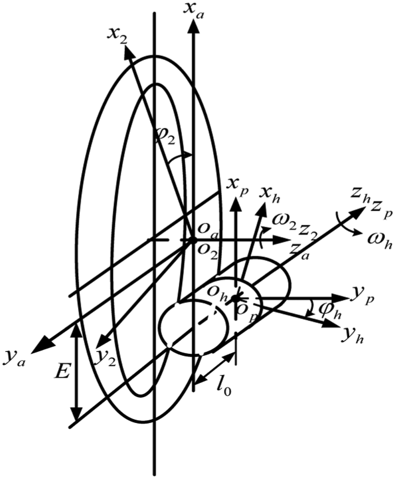
Coordinate systems for derivation of gear.
Movable coordinate systems
where
The magnitude of
Variable parameters

where
The following equation provides the tooth surfaces
where
In the process of manufacture of spiroid gear by an imaginary hob, the generated tooth surfaces
Geometry of spiroid gear
The design of the raised novel geometry of the spiroid gear is based on the following ideas:
The basic geometry of the spiroid gear is imaginary generated by the use of a virtual pinion cutter based on the method of the conventional gear generated by a hob (Figure 2).
The novel tooth geometry with skew double-crowned gear is achieved by the application of ease-off modification methodology of contact path and contact line direction.
The modified tooth geometry of gear will be offered as die cavity surface that is manufactured by electrical discharge or CNC machine directly.
The geometry of double-crowned gear will be manufactured by precision casting process using such modified geometry of die cavity.
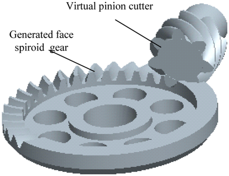
Spiroid gear generated by a virtual pinion cutter.
Geometry of the imaginary generating fully conjugated spiroid gear
In theory, the fully conjugated tooth surfaces of spiroid gear can be obtained by using a spiroid cylindrical pinion as a virtual hob to produce the gear as shown in Figure 3. The equations of the tooth space surfaces of left-hand involute spiroid pinion can be described directly. The tooth surfaces I and II of the involute pinion generate the concave and convex tooth surfaces of the gear, respectively (Figure 3).
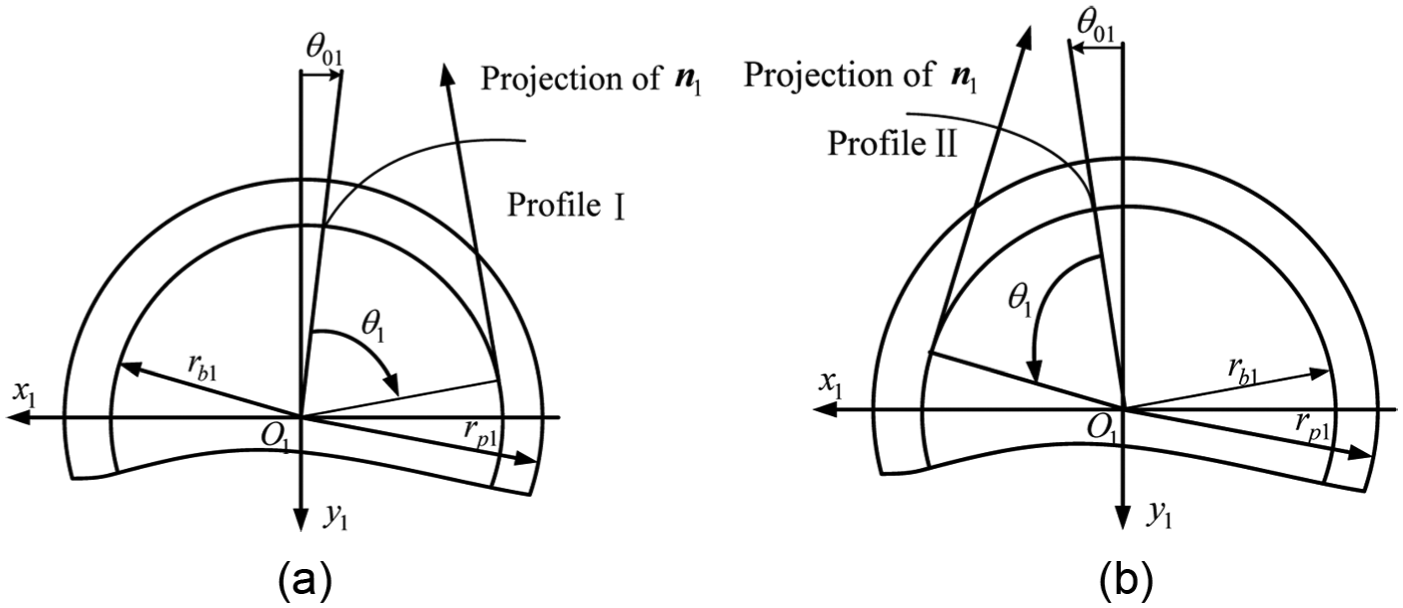
Cross sections of the spiroid pinion tooth surfaces for (a) Profile I and (b) Profile II.
The tooth surfaces I and II of the pinion are represented by the following equations
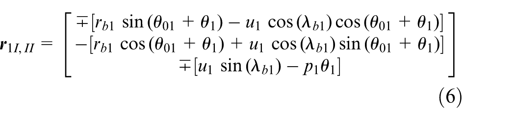
The unit normals to the tooth surfaces I and II are determined in coordinate system
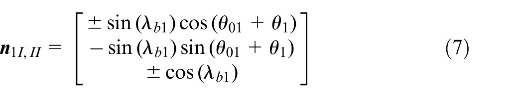
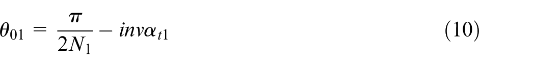
where the upper and lower signs correspond to I and II tooth surfaces for equations (6) and (7). Parameters
The lead angles

where

The above-mentioned half of regular width
According to equations (4) and (5), the tooth surfaces are represented by the following equations
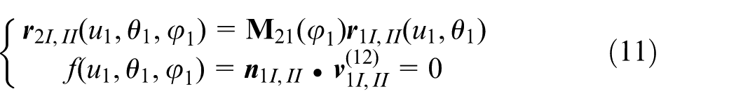
where
where

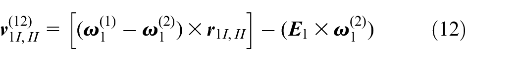
where
Equation (12) is confirmed by the following
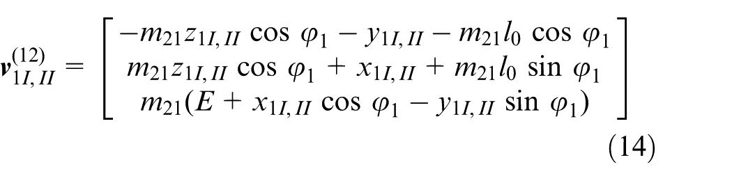
where
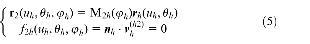
Considering equations (7) and (14) simultaneously, the meshing equation of the generated spiroid gear and the virtual hob cutter is determined as
where
From the above mentioned, it is known that a fully conjugated gear tooth can be obtained by using the spiroid pinion as the virtual hob cutter to manufacture the spiroid gear. If this fully conjugated gear tooth surface is denoted by
Geometry of developing double-crowned gear
The research of the gear drive needs to develop a novel geometry of double-crowned gear using ease-off modification methodology for the fully conjugated gear. Applying such double-crowned tooth geometry as the baseline of die cavity allows to manufacture the spiroid gears with the same geometry. Such gear drives with involute spiroid pinion will meet the requirement of point contact rather than line contact, get a favorable function of transmission errors, avoid edge contact and reduce the sensitivity of bearing contact of misalignment.
Geometry of profile-crowned gear
In this study, the profile-crowned gear geometry may be performed by the use of a pre-designed controllable function of transmission errors in the desired contact path direction, while the imaginary generation of gear by a virtual spiroid pinion cutter will be considered.
Traditionally, the transmission errors are termed as the differences between the real rotation angle of the output gear and the theoretical angle of the input gear, which are defined as 15
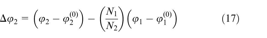
where
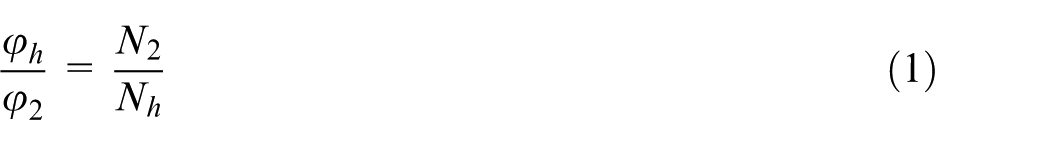
If the generation of the spiroid gear by the virtual pinion cutter is deemed to the gear pair actual meshing transmission process, and the angles of rotation are met with equation (1), the error

In the research, a fourth-order polynomial function is chosen as the pre-designed function of transmission errors

where
Figure 4 shows the procedures to pre-design a function of transmission errors for
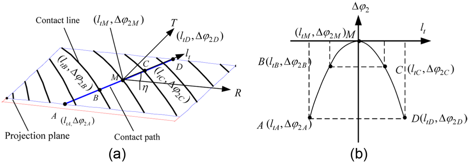
Profile modification: (a) design of contact path and (b) pre-designed function of transmission errors.
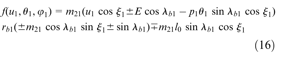
From equation (16), we know that the parameter
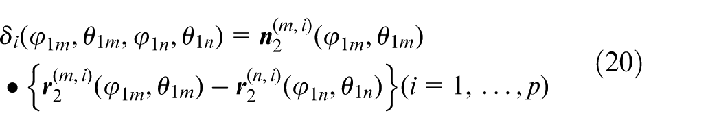
where p designates the number of topographical grid points on the surface of the spiroid gear.
Profile ease-off modification can obtain the tooth geometry of crowned gear with a desired favorable shape of transmission error function. Theoretically, however, such gearing is still conjugate to the spiroid pinion and in line contact instantaneously. Those conditions of contact cannot guarantee the locus along the desired contact path, which is insufficient to reduce the shift of bearing contact of misalignment. Therefore, for achieving point contact of gear drive, it requires another surface modification along contact line computationally based on the previous tooth modification.
Geometry of double-crowned gear
To design an optimal ease-off topography of contact line direction, the surface modification can be performed to satisfy the demand of developing the gear geometry with double-crowned tooth surface. The ease-off topography is developed by computer-aided design technology, and the ease off in normal at grid point is calculated computationally based on the conjugate tooth surface geometry
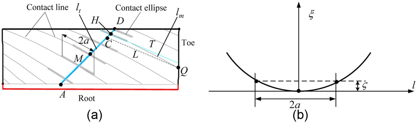
Surface modified by computer-aided design: (a) pre-designed contact ellipse and (b) parabola curve of modification.
The function of modification of contact line direction is represented as follows
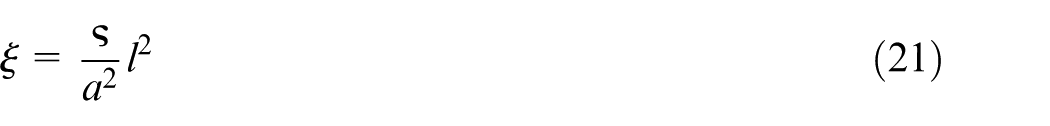
where
Superimposing the ease off on the tooth surface
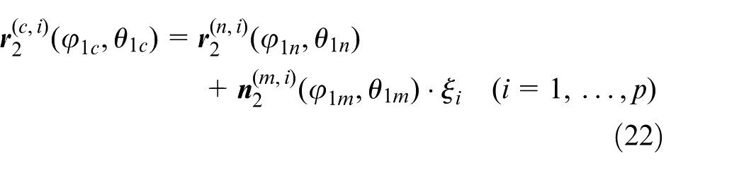
Figure 6(a) illustrates the synthetic ease-off topography in both contact path and contact line direction. Figure 6(b) provides the geometry of crowned tooth and the non-modified tooth geometry for spiroid gear.
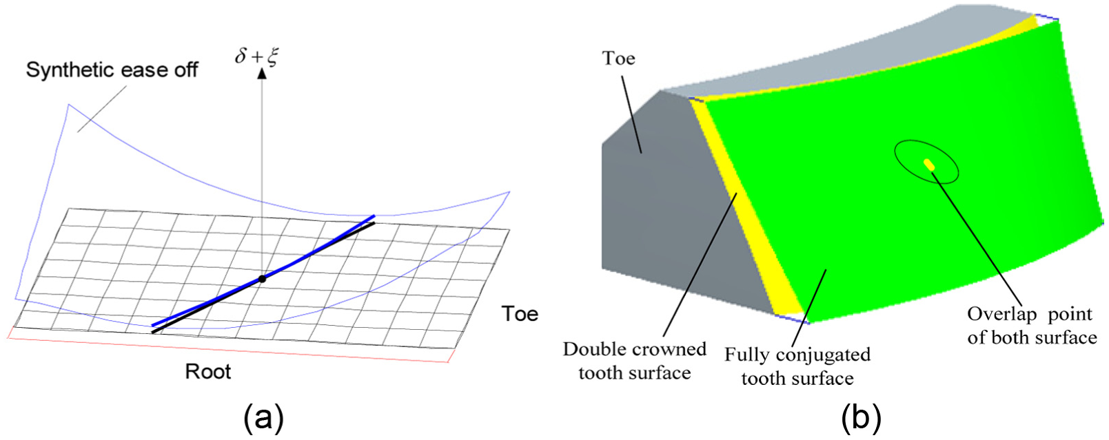
Synthetic (a) ease-off topography and (b) double-crowned tooth surface.
Investigation of numerical examples
Two types of geometry of spiroid gears that were manufactured by CNC machining have been provided to validate the generation of surface modifications of the gears by using the ease-off topography (Figures 7 and 8). NC codes are programmed automatically by use of Unigraphics NX software. The mated geometry of spiroid pinion is generated by the hob process. An alloy of Cu + Zn is selected as the materials of gears.
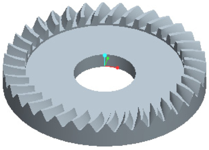
Model of spiroid gear.
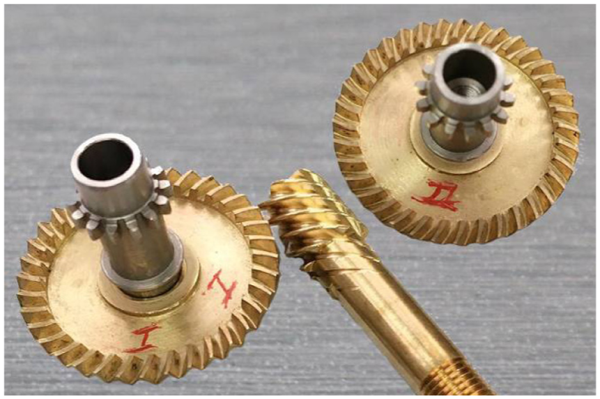
Manufactured two types of spiroid gear.
Design parameters
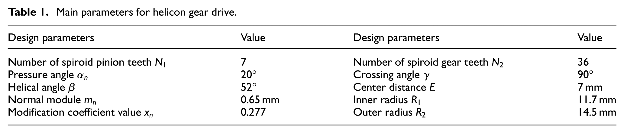
The topographies of the produced tooth geometry are determined by the parameters of surface modifications listed in Tables 1 and 2. Two numerical cases are offered to study the ease-off modifications and the stability of contact patterns of helicon gear drives. The involute spiroid pinions are used for all the following examples.
Main parameters for helicon gear drive.
Design parameters for spiroid gear tooth surface modifications of two cases.
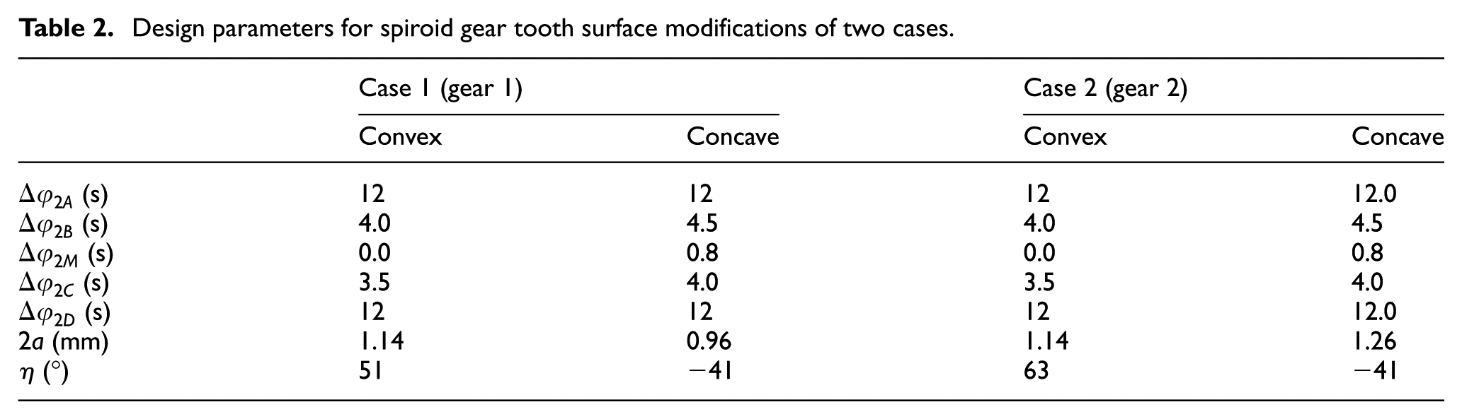
Two cases are developed to trade off study the differences of tooth geometry and results of tooth contact analysis (TCA) by changing the design parameters of surface modification. Each case corresponds to one type of gear that includes both convex and concave tooth surfaces. Based on the design of the inner radius of the gear, undercutting is avoided in the convex side, but occurred in the concave surface. The article uses the convex tooth geometry of the two types of gears as objective to investigate the ease-off topographies influenced by the desired contact paths. That is, the parameters of bias angle
The computer programs were developed to conduct imaginary generation, surface modification and computer simulation 16 of spiroid gear drives. It is allowable to get ease-off topographies of contact path and contact line directions, synthetic ease-off topographies, geometry of double-crowned gear tooth and the results of TCA. However, it must be stated that the errors of alignment are not introduced for TCA in these two cases.
Discussion and analysis of two cases
Figures 9 and 10 illustrate the ease-off topographies of surface modifications and the results of TCA for case 1 and case 2, respectively. The fully conjugated surfaces
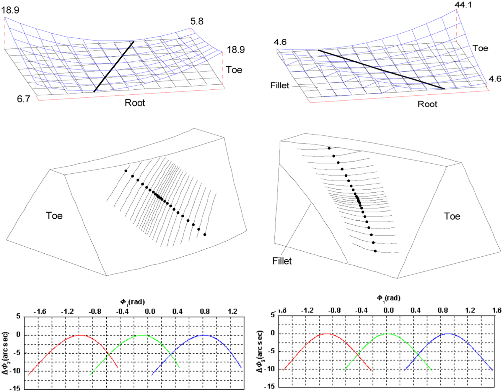
Ease-off topographies and original TCA for case 1: (a-c1) convex (unit: µm), (a-c1) concave (unit: µm); (b-c1) convex,(b-c1) concave and (c-c1) convex, (c-c1) concave.
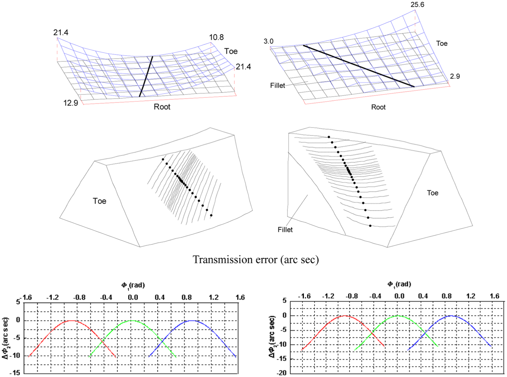
Ease-off topographies and TCA for case 2: (a-c2) convex (unit: µm), (a-c2) concave (unit: µm); (b-c2) convex, (b-c2) concave and (c-c2) convex and (c-c2) concave.
For the convex sides, the given bias angles
Figures 9(b-c1) and 10(b-c2) show the bearing contact on both the tooth surfaces of gear, respectively. The parabolic curve of the actual transmission error is provided by the actual rotation angles
With respect to the TCA of the convex tooth surfaces, the results show that the magnitudes of transmission error of a cycle are 5 and 6.1 arc seconds, respectively. The contact ratio determined by the bias angle
About the TCA of the concave surfaces, the actual transmission errors
Using the results discussed above, the contact ratio of gear drive is not equivalent when the concave side or the convex side is chosen as the driving surface. Obviously, the contact ratio of the former is higher than the latter. This advantage makes the concave surface of gear as driving side of the helicon gearing in general.
The TCA of computer simulation illustrates the bearing contact on both the gear tooth surfaces, which means point contact is achieved by the modification of the gear tooth surfaces.
Conclusion
Applying the ease-off topography, the article proposed a novel geometry of double-crowned gear for the fully conjugated spiroid gear manufactured by precision casting process. The results of the performed research allow the following conclusions to be drawn:
The tooth geometry of crowned gear is developed first along the desired contact path from pre-designed function of transmission errors in the process of imaginary generation, and then ease offs are designed and calculated computationally along the contact line. The novel tooth geometry of double-crowned gear is obtained by superimposing the desired ease offs of the contact line direction to the profile-crowned tooth surface.
The results of numerical examples demonstrate that the ease-off modification methodology make the fully conjugated tooth gear as a double-crowned tooth geometry, which enables the meshing of gear pair to be point contact rather than line contact. Moreover, the paths of contact, normal deviations and initial contact point are obtained from those ease-off topographies.
Computer simulation programs have been developed for the double-crowned gear drive, which allow us to get the perfect function of transmission errors and the desired bearing contact.
In the state of the art, the proposed novel double-crowned tooth geometry can be produced by high-precision die casting or by CNC machining directly. Especially, mass production of the spiroid gear will be low cost and high efficiency.
The proposed novel tooth geometry of double-crowned gear has been applied successfully to produce several types of geometry for spiroid gears by precision casting process. In addition, the ideas of ease-off modification of tooth surfaces can be applied to other types of gears manufactured by forging or casting process.
Footnotes
Declaration of conflicting interests
The author(s) declared no potential conflicts of interest with respect to the research, authorship, and/or publication of this article.
Funding
The author(s) disclosed receipt of the following financial support for the research, authorship, and/or publication of this article: This study was financially supported by the Ningbo Beilun Haibo Machinery Co., Ltd and Shaan Xi, China of Science and Innovation (project ref. 2012JM7003).