
Abstract
The cold ironing process of a warm forged spur gear was applied to investigate the elastic distortions arising by the behavior of die elastic expansion and gear elastic recovery in this article. An elasto-plastic finite element simulation was performed to analyze the elastic behavior characteristics of gear and die. The effects of interference between gear and die on the elastic distortions were investigated through finite element simulation and experiment, respectively. The change of geometrical profile and dimension of the gear tooth were measured; the estimated dimension of ironed gear by finite element simulation was fitted to the experimental results well within the range of 5% relative error. Furthermore, in order to improve the dimensional accuracy of final forged gear, this study proposed a die cavity compensation method to compensate cavity of the ironing die, which was obtained by shrink fitting a outer ring into the initial ironing die. The optimum radial interference between stress ring and initial shrink-fitted die was calculated based on the Lame formula and thick wall cylinder theory. Finally, an experiment according to the proposed die cavity compensation method was carried out to examine the validity of analytical results and demonstrated that predicted dimensions could be achieved and dimensional accuracy greatly improved. It was shown that the manufacture gear satisfies the IOS6 class by measuring the iron-forged gear.
Introduction
Dimensional accuracy of forged net-shape components is one of the most important manufacturing criteria in precision forging, especially for forging of complex structural components. As a post-forging operation in precision forging, cold ironing process plays a crucial role in improving the dimensional accuracy of components. Since the dimensional accuracy of ironing forged parts is largely influenced by elastic behaviors of the components and tool, a comprehensive understanding of elastic deformation characteristics of components and tool in cold ironing process is essential. Up to now, many researches have been engaged into elastic behaviors of components and tool in cold forging by the numerical and experimental analyses. These articles can be summarized as follows: Chang et al., 1 and Stone et al. 2 investigated the use of ironing process to warm forged gears and thick-walled cylinders, revealed the relationship among process variables and demonstrated that ironing had beneficial effects on the final dimensions and surface finish of the test-pieces. Lee et al. 3 introduced the drum clutch with inner gear shape manufacture using cold ironing process; a rigid-plastic finite element (FE) simulation was applied to estimate the dimensional accuracy of the inner gear shape according to the variables such as the punch shape, the punch approach angle and the thickness reduction ratio. Five modeling approaches had been analyzed by Lee et al. 4 to investigate a favorable FE model for cold forging process, where the modeling simultaneously considered the die and components as deformable bodies, the finite element method (FEM) analysis results showed a good agreement with experimental data. Lee et al. 5 measured the elastic deformation of a die using strain gauges in closed die upsetting and concluded that the dimensional difference between die and forged part had a linear relationship. Several works were also concerned to dimensional accuracy related with elastic deformation of tool and component.6–11 The majority of these studies1–11 concerned mainly on the elastic behavior characteristics of tool and the component in cold upsetting and cold extrusion instead of cold ironing process, and less research is engaged into spur gear parts precision forming. There is almost no research reporting about the elastic deformation characteristics for spur gear cold ironing process, especially focused on elastic deformation trend of involute curve profile.
The requirement for the dimensional accuracy of spur gears for automobile gear-boxes has increased with the development of auto industry. Considering character of high diameter-to-thickness ratio of spur gears for automobiles requires high forging load, an elevated temperature forging is performed to forge gear in order to overcome this defect. This results in low quality of the dimensional accuracy of forged gear due to the contraction of the metal after cooling. Therefore, a cold forming of ironing process is applied subsequently to reduce the dimensional errors due to thermal distortions. But in most cases, dimensional accuracy of iron-forged gears is below standard and cannot reach the requirement for using. This dimensional difference is mainly influenced by elastic behavior of tool and component, thermal influence due to plastic deformation, machine elasticity. All factors above cause the dimensional errors of tooth profile. Among these factors, the elastic behavior of tool and component material is the most critical factor on dimensional accuracy of final product. Since the standard accuracy of precision gears is within the range of several micrometers and the elastic deformation characteristic of cold ironing process for spur gears has not been comprehensively researched, it is important to conduct an extensive analysis on the elastic deformation characteristics of tool and component and die cavity modification.
A warm forged spur gear used in automobile gear-box is applied in this study. FE analysis is undertaken to investigate the characteristics of elastic expansion of the die and elastic recovery of the gear in cold ironing process. The effects of interference between gear and die on the elastic distortions are also investigated by FE simulation and experiment, respectively. A die cavity modification method is proposed to improve dimensional accuracy of final product. Finally, an experiment is carried out to validate FEM results and to provide a method with which to modify the geometrical shape of die cavity.
Experimental setup and FE simulation
Experimental work
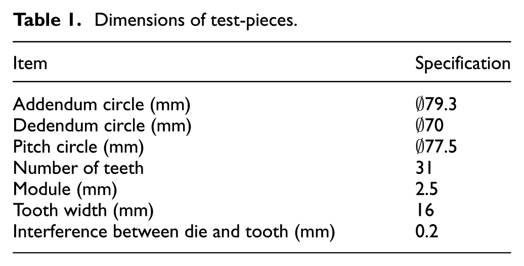
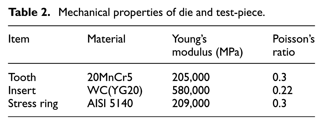
The cold ironing of a reverse gear, as shown in Figure 1, is chosen for experimental and FE analysis. Table 1 shows dimensions of test-pieces. As mentioned above, considering the character of the high forging load in gear tooth forming, a warm forging process should be preceded. There is an allowance between the external of test-piece and the internal of cold ironing die, which varied according to parameters. A schematic of interference between test-piece and die is shown in Figure 2. Since the requirement for dimensional accuracy of final product is focused on involute curve profile, the interference (I) is only set on involute curve region, while the root and top of the tooth are not constrained by the die. The setup of the ironing process is shown in Figure 3. Shrink-fitted die is used for cold ironing die in order to increase the resistance of the die insert against forming pressure. To reduce the elastic expansion due to internal pressure, the insert die is made in tungsten carbide and the outer ring is made in 40Cr medium carbon alloy steel; the cooperating relationship between them is interference fit. The test-pieces are pre-treated with spheroidized annealing and the material is 20MnCr5 steel, which is one of the popular carburizing steels for gears. Phosphating and saponification process are used to decrease surface hardness and lubricate test-pieces, respectively. The test-pieces are pushed through the ironing die using a Denison 315t hydraulic press at a rate of 10 mm/s. Coordinate Measuring Machine (CMM) is used to measure the profile of ironed tooth surface. Table 2 shows the mechanical properties of tool and test-piece material.
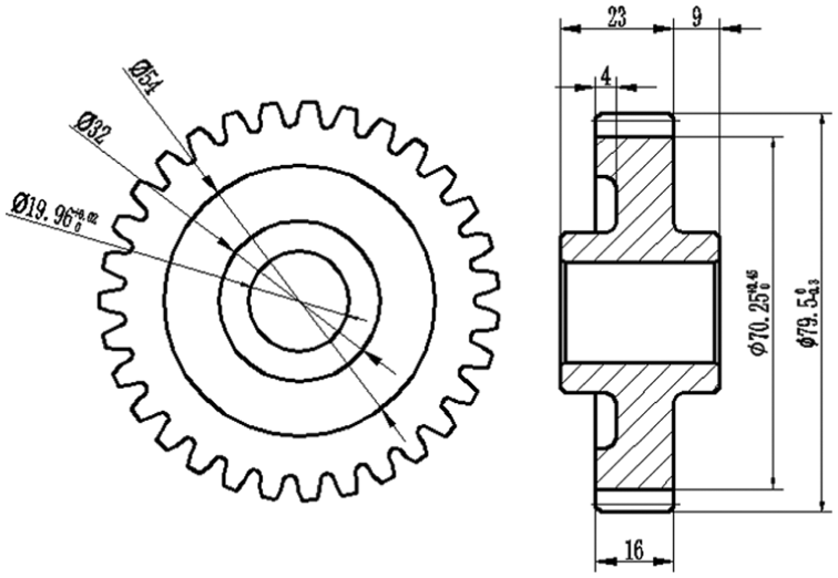
Final shape and dimensions of the reverse gear.
Dimensions of test-pieces.
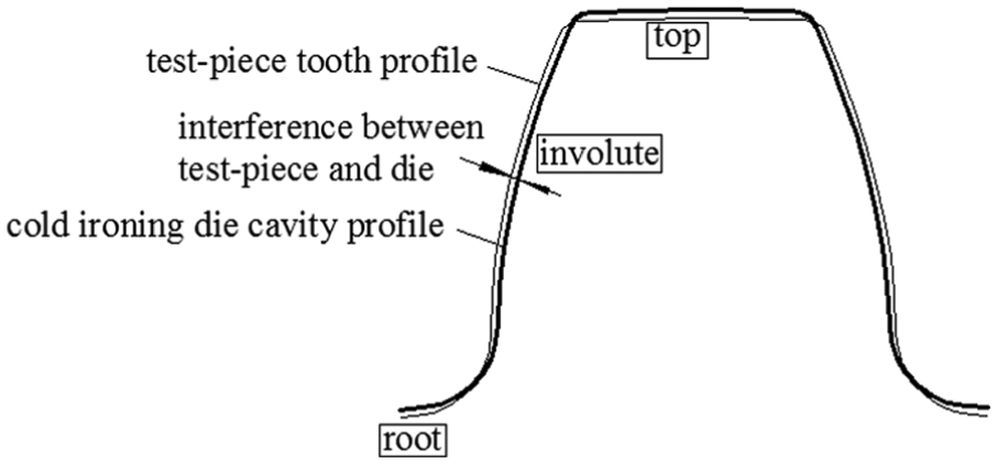
Interference between test-piece and cold ironing die.
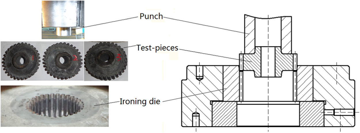
Initial cold ironing process setup.
Mechanical properties of die and test-piece.
Model and conditions of FE simulation
Deform was used to investigate the elastic deformation characteristics of spur gear for cold ironing process; the material type of the ironing die and tooth is defined as elastic and elasto-plastic model, respectively, to allow for elastic expansion of the die under internal pressure and elastic recovery of the tooth after being ejected from die. The type of cells is hexahedron, which is beneficial to extract information about the displacement and strain of die and tooth, and this can also avoid the unnecessary deviation when extract data. Due to the symmetrical structure, a 1/31 section of gear and tools are used for FE simulation, as shown in Figure 4. For validation of FEM results, the geometric dimensions and material properties of the tooth and die in FE model are similar with that used in experiment. Consequently, a shrink-fitted die with a WC insert and a steel outer ring is established in FE model. With respect to the effect of elastic deflection of insert die due to the pre-stress by shrink fitting, a boundary condition of fixed displacement in radial direction is set up on the internal tooth surface to eliminate the dimensional change of the insert die in simulation. The friction constant factor is assumed to be 0.2 in this cold ironing simulation.
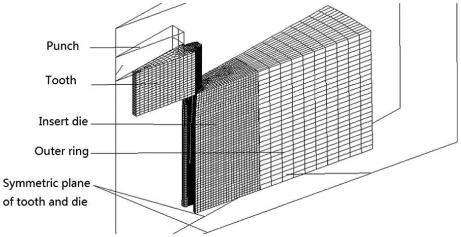
FE model for cold ironing simulation.
Results and analysis
Deformation stage
In cold ironing process, the tooth is pushed through the ironing die by punch and the metal on tooth surface is extruded from lower end to upper end. The deformation of the tooth at three stages is shown in Figure 5. At the beginning of the process (Figure 5(a)), the tooth is laid flatly at the slope surface of die approach angle. Then, the tooth is pushed into ironing die cavity with the development of punch stroke. During this stage (Figure 5(b)), the die cavity undergoes a radial expansion due to the pressure exerted by the tooth in contact region, and the profile of tooth inherits from the elastic deformed die cavity in this stage. Elastic recovery occurs after the tooth is rejected from the ironing die (Figure 5(c)); the reason of this deformation is due to the redistribution of residual stresses. As elastic recovery of the tooth is proceeded based on the profile of elastic expanded die cavity, total deformation values are obtained by summing elastic expansion of the die and elastic recovery of the tooth, as shown in Figure 6.
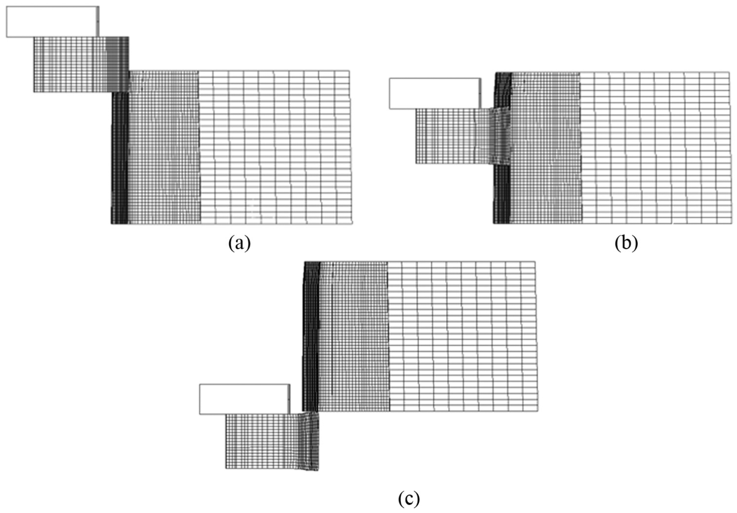
Mesh deformation for each stage: (a) initial stage (0% stroke), (b) die elastic expansion (40% stroke) and (c) tooth elastic recovery (100% stroke).
Schematic diagram of dimensional changes for die and tooth.
The shape of the simulated tooth is compared with the experimentally obtained shape of ironed tooth, as shown in Figure 7. A distortion is observed at the lower end and the upper end of tooth region, respectively. The reason of this phenomenon could be explained as follows: the tooth undergoes a radial compressive stress exerted by the ironing die in contact region during plastic deformation. Since the bottom and top end faces are free surfaces, radial pressure leads to an inside metal flow in radial direction in the region of bottom and top end faces, which results in distortions at the lower end and upper end of tooth region.
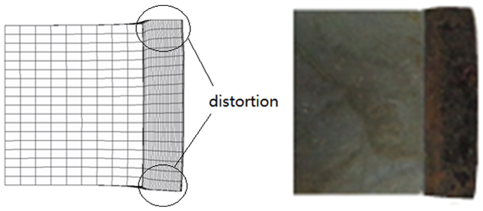
Comparison of ironed tooth and simulation result: (a) numerical tooth and (b) experimental tooth.
Interference between die and tooth
Three different interferences between die and initial tooth (as shown in Table 1) are performed experimentally and by FE simulation in order to investigate the effect of this variable on dimensional accuracy. The experimentally obtained profiles of ironed tooth measured by a CMM are compared with that obtained from simulation (Figure 8). According to the criterion of spur gear tooth measurement, the locations of measurement are along profile line at middle of tooth width and vertical line at pitch circle cylinder, which correspond to the profile line “4” and vertical line “c” in simulation separately.
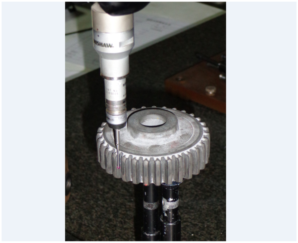
Measurement of cold ironed gear by a CMM.
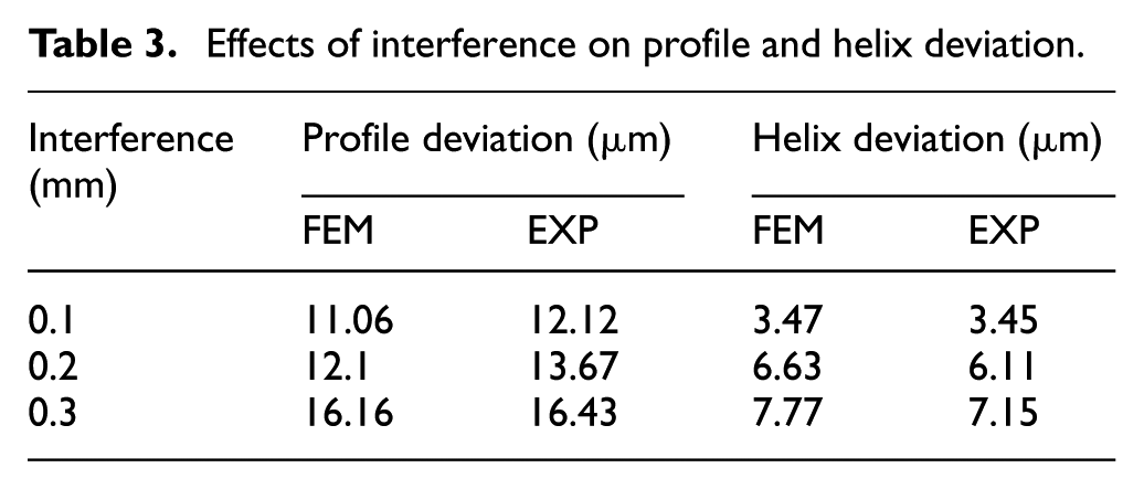
The numerical and experimental measurement profiles are shown in Figure 9. The result indicates that the tooth shapes for all interferences are similar. The more the interference is increased, the more the ironing load is needed. The larger forming load induces the more elastic expansion values of the die and the distortions are improved, which leads to the higher dimensional errors on tooth shape. The predicted dimensional errors in simulation correlate well with those measured experimentally, even though the experimental measurements are slightly larger than that in simulation. The relative error between experimental and numerical results is within the range of 5%. The reason of the discrepancy could be explained as follows: the effect of the heat of plastic deformation on dimensional errors is neglected in FE simulation. The effect of interference on profile deviation and helix deviation of the ironed tooth is calculated based on numerical and experimental dimensional errors and is shown in Table 3. It is concluded that a small interference is advantageous for high dimensional accuracy of final products. Therefore, the validity of numerical results for the dimensional errors prediction and the optimal interference variable selection are demonstrated by comparing with the experimental results.
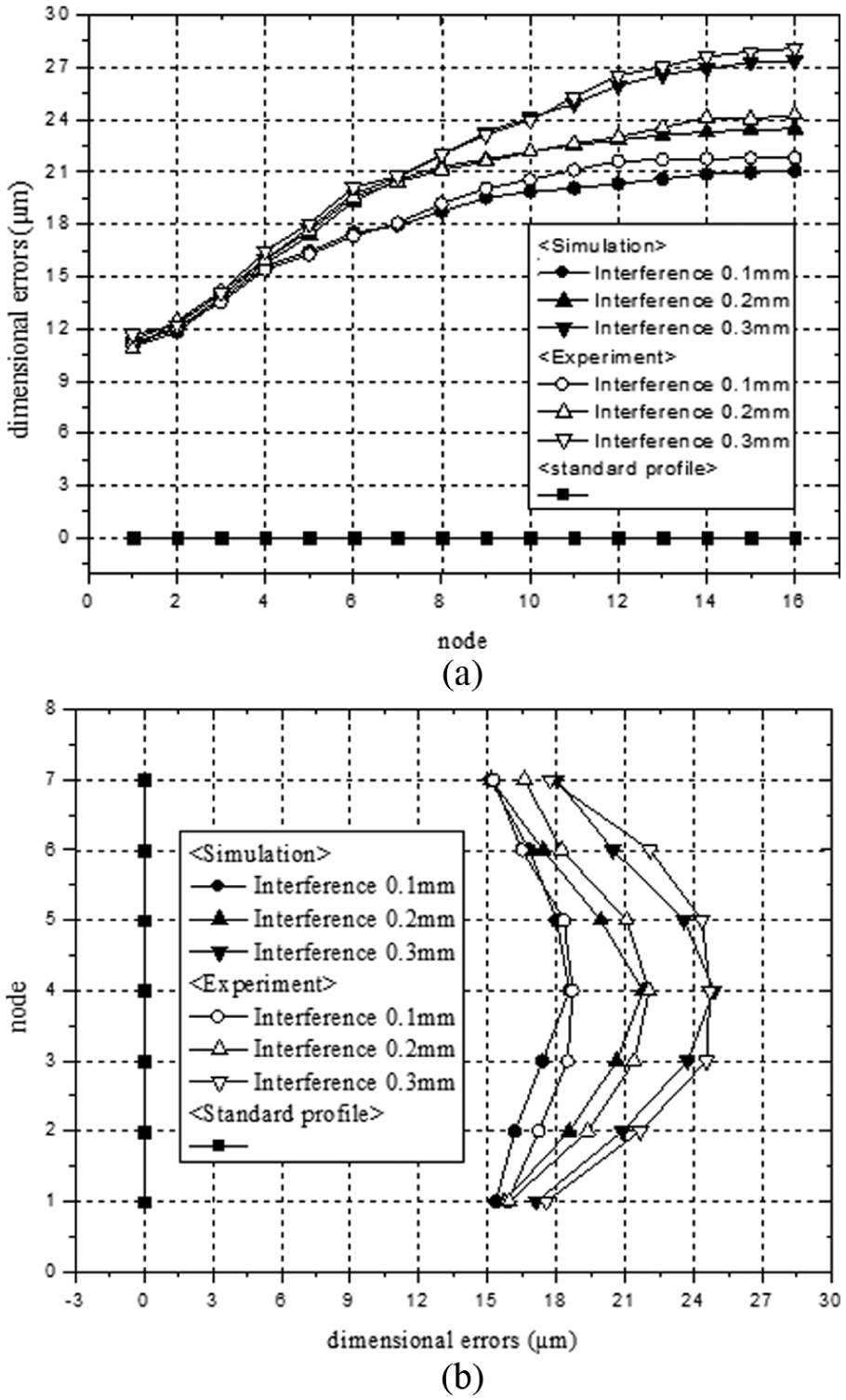
Influence of interference on tooth shape: (a) profile line and (b) vertical line.
Effects of interference on profile and helix deviation.
Elastic expansion of ironing die
Die cavity expand elastically during the forming operation could induce tooth-form errors. With respect to the function of spur gear, the dimensional accuracy at involute curve region is more important than that at root and top regions; for it is where components accomplish power transmission, the research only focused on involute curve region. Since profile deviation and helix deviation are the most two important items in gear measuring, an extensively research on elastic deformation behavior of die and tooth in profile direction and vertical direction is necessary.
The amount of elastic deformation could be reflected by the measuring displacement changes of nodes in post process of FEM. In order to investigate the elastic expansion of the die quantitatively in profile direction and vertical direction, deformations of nodes on die cavity surface are observed. The measured nodes locate on seven profile lines (range from “1 to 7”) and five vertical lines (range from “a” to “e”), the distribution is shown in Figure 10. In profile direction, sixteen nodes are selected equidistantly on each involute curve, and each node is numbered from small to large according to the direction from base circle to addendum circle. In vertical direction, seven intersections of each vertical line with every profile line are defined as measuring points on each vertical line, and each node is numbered from small to large according to the direction from lower end to upper end.
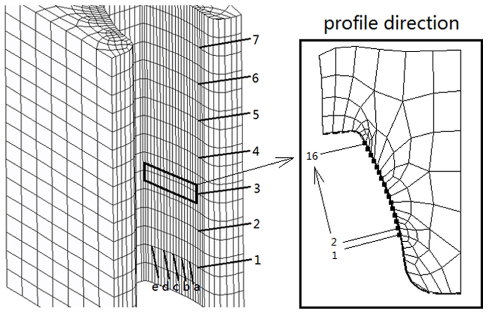
Distribution of measuring nodes on die cavity surface.
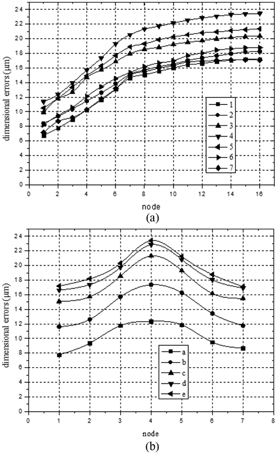
The profile of elastic deformed die cavity is obtained according to the displacement changes of measuring nodes. The dimensional errors due to elastic expansion in profile direction and vertical direction are shown in Figure 11. It is observed that the dimensional errors due to elastic expansion increase gradually in direction from base circle to addendum circle on profile line. On vertical line, the dimensional errors in lower end and upper end regions are smaller than those in the middle of tooth width, which leads to a crowned shape on die cavity surface in vertical direction.
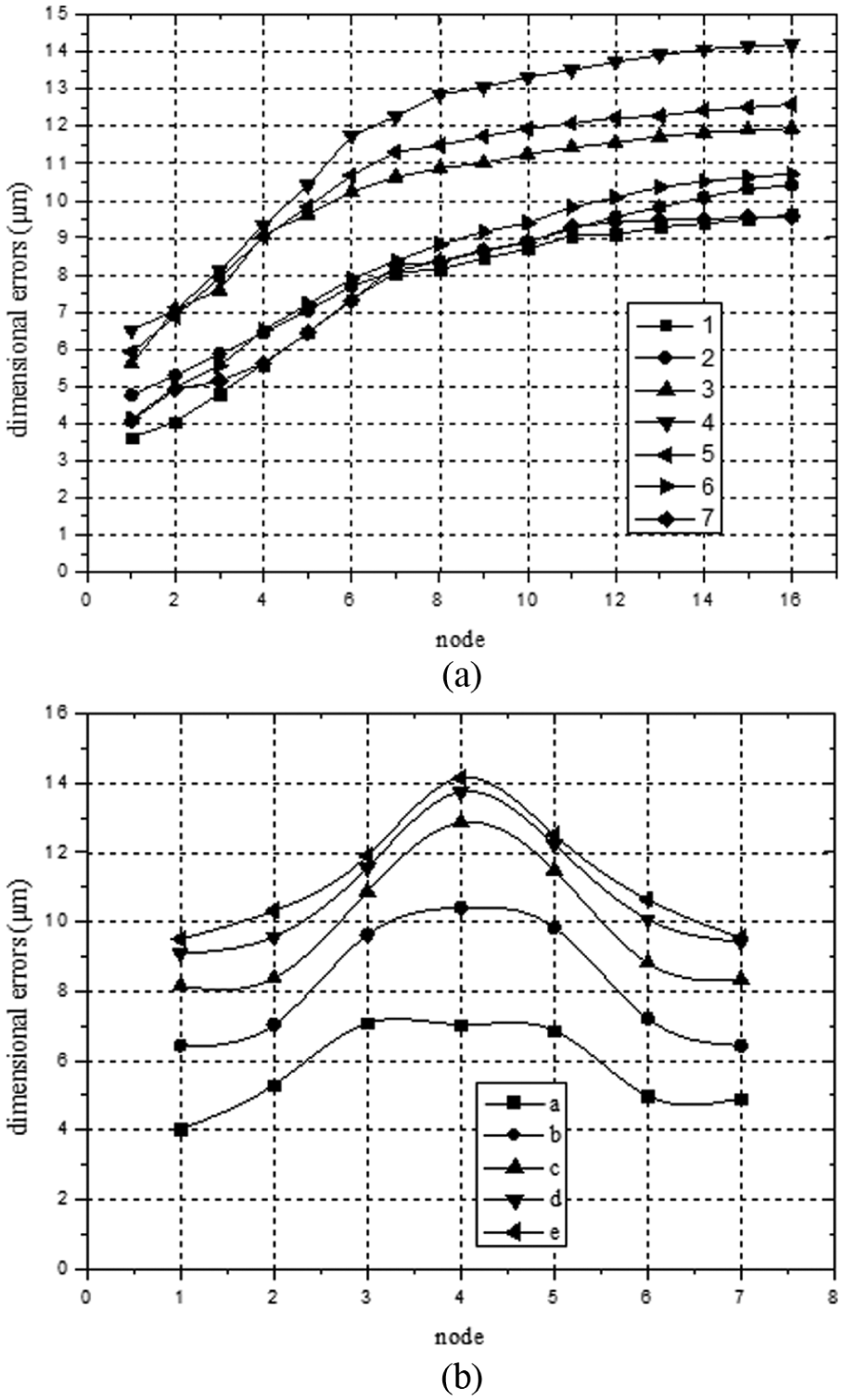
Effect of elastic expansion of the die on dimensional errors: (a) profile line and (b) vertical line.
Elastic recovery of tooth
Further deformation of the tooth will occur due to relaxation of the pressure between die and tooth. Elastic strain energy is aggregated at tooth surface during cold ironing deformation. The accumulated energy is released after the tooth has passed through the die, which induces elastic recovery of the tooth. The method for analyzing elastic recovery of the tooth is similar to that for elastic expansion of the die. In order to evaluate the amount of tooth deformation in profile direction and vertical direction, deformations of measuring nodes are observed. The location of measuring nodes on tooth surface is corresponding to the ones on die cavity surface, as shown in Figure 12.
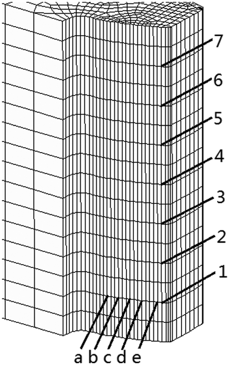
Distribution of measuring nodes on tooth surface.
Figure 13 shows the dimensional errors induced by elastic recovery of the tooth in profile direction and vertical direction. The influence of elastic recovery on dimensional errors in profile direction is similar to that of elastic expansion. However, when it comes to vertical direction, the influence of elastic recovery of the tooth on dimensional accuracy is smaller than that of elastic expansion of the die. The range of dimensional discrepancy is within 2 µm on each vertical line, which means the effect of elastic recovery of the tooth on dimensional errors could be neglected in vertical direction.
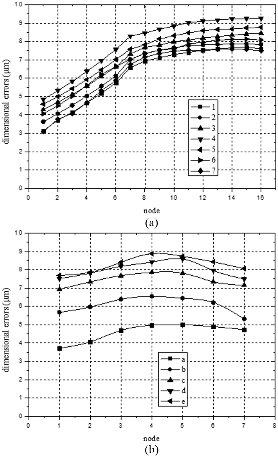
Effect of elastic recovery of the tooth on dimensional errors: (a) profile line and (b) vertical line.
Analysis of elastic deformation
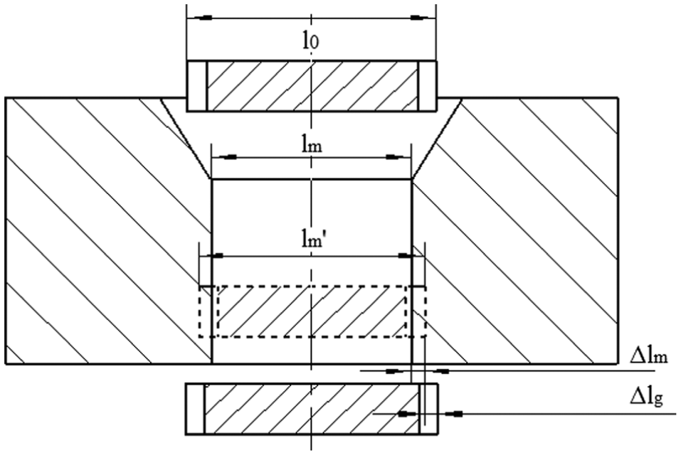
In cold ironing process, the die cavity subjects to radial pressure exerted by the tooth in contact region, which results in radial expansion of the die cavity. Figure 14 shows the profile changes of the die cavity elastic expansion. The profile line of die cavity is obtained by fitting measuring nodes into a curve according to FEM results. It is observed that the expansion of all the points on the profile line along radial direction. A specification of one point on profile line is described in Figure 14:
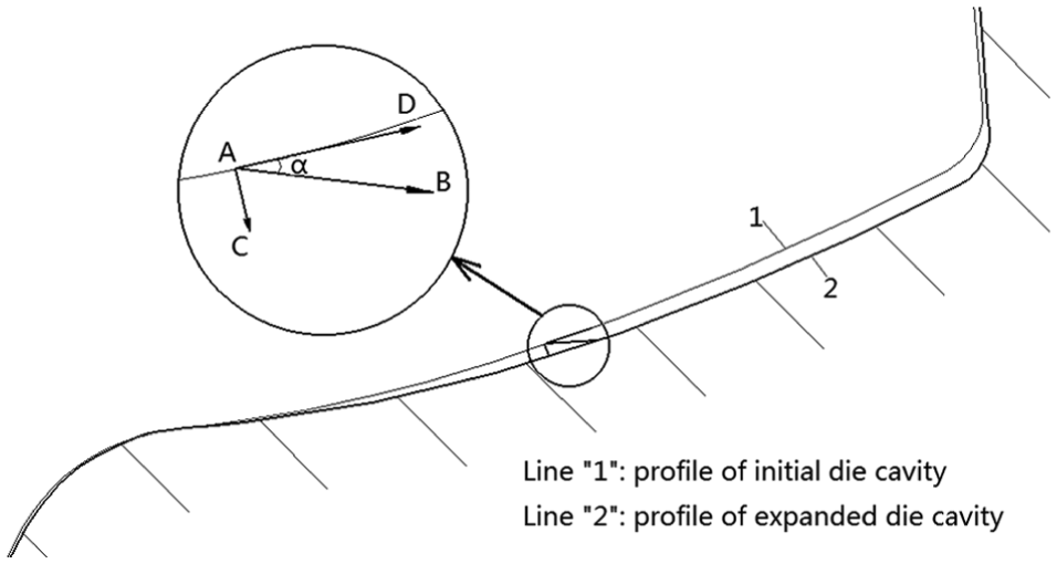
Comparison between the changes of initial die cavity and expanded die cavity on profile line “4.”
The reason why the dimensional errors on die cavity surface shows a crowned shape in vertical direction could be explained by the tooth deformation history as follows: during the tooth passes through the ironing die, distortions are observed at the lower and upper ends of tooth region, which results in smaller interference between tooth and die compared with the middle of tooth width. As a result of that, plastic deformation of the tooth is smaller at the lower end and upper end of the tooth due to distortions. Since the pressure in contact region is proportional to the amount of plastic deformation, the lower pressure exerted on die cavity will result in less die expansion and therefore, a crowned shape is shown on die cavity in vertical direction.
Dimensional errors of final product
As mentioned in previous analysis, elastic deformation consists of the elastic expansion of the die and elastic recovery of the tooth. So the total dimensional errors of the final product are calculated by summing dimensional errors due to elastic expansion of the die in Figure 9 and dimensional errors due to elastic recovery of the tooth in Figure 13, as shown in Figure 15.
Dimensional errors of the final product: (a) profile line and (b) vertical line.
The characteristics of dimensional errors for cold ironed spur gear could be concluded as follows: dimensional errors show a tendency of increasing from base circle to addendum circle in profile direction, while dimensional errors in vertical direction give a crowned shape profile.
Die cavity modification
Theoretical background
It is concluded that the discrepancy of dimensional change on tooth surface induces the decrease of dimensional accuracy for final products. The requirement for the dimensional accuracy of the spur gear analyzed in this study is between IOS6 class and IOS7 class, which requires the profile deviation and helix deviation to be within 12 and 11 µm, respectively. The experimentally measured values of helix deviation are all within an error of 11 µm, which satisfies with IOS6 class. However, profile deviations exceed the range of criterion value of 12 µm, even for the tooth with initial interference value of 0.1 mm. A compensation for cold ironing die cavity to decrease profile deviation of final products is necessary.
Since the shape of ironed tooth is slightly larger than desirable tooth shape according to above analysis, the dimensions of die tooth cavity should be decreased. Because the dimensional errors occur as a result of the elastic behavior of die and tooth, both must be considered in the analysis of the die compensation.
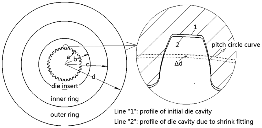
In cold ironing process, a shrink-fitted die by shrink fitting the die insert into one or more shrink rings is applied to increase the resistance of the die insert against pressure exerted by tooth. Interference between the die insert and the shrink ring imposes a compressive pre-stress on the die insert. Consequently, the compressive pre-stress induces elastic deformation of the die, which results in the dimensional change of the die cavity. The displacement direction of die cavity by shrink fitting is radial inside, which is opposite to that of elastic expansion of the die and elastic recovery of the tooth. As a result of that, the dimensional errors could be decreased by shrink fitting an outer ring into the initial ironing die. In this study, a new die cavity modification method by shrink fitting an outer ring into the initial shrink-fitted die is carried out to improve dimensional accuracy of final products.
Shrink fit design for ironing die modification
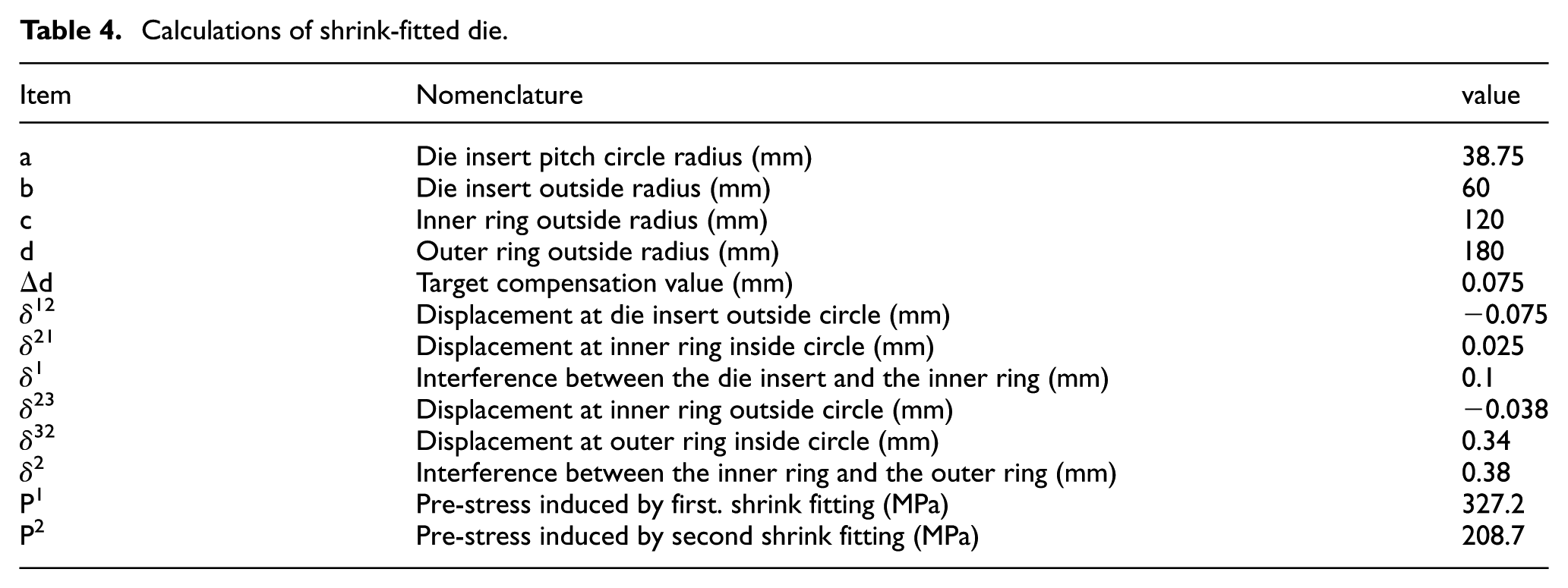
According to thick wall cylinder theory, the maximum elastic bearing capacity could be achieved when the die insert and shrink ring yield simultaneously in shrink fitting process (Figure 16). The design criterion of initial shrink-fitted die used in this study is to maximize elastic bearing capacity. The geometric parameters of initial shrink-fitted die are calculated based on thick wall cylinder theory, as shown in Table 4.
Elastic deformation by shrink fitting process.
Calculations of shrink-fitted die.
Since the strength of ironing die has been improved by initial shrink fitting process, the second shrink fitting process should be focused on improving dimensional accuracy of final products. As mentioned above, the die cavity compensation is accomplished by shrink fitting an outer ring into the initial ironing die. According to thick wall cylinder theory, the amount of elastic deformation due to shrink fitting relates to the pre-stress exerted on the initial ironing die. Meanwhile, the pre-stress is determined by the interference between initial ironing die and the outer ring. Therefore, the calculation of the interference is the vital factor for modification.
In this study, the elastic deformation value of the die cavity due to shrink fitting is based on the dimensional errors of the ironed tooth. Since the small interference has a beneficial result on dimensional accuracy, the result of the ironed tooth with a interference of 0.1 mm is used. The compensation value is defined as the radial deflection of the ironed tooth at pitch circle. The calculation of the optimal interference between initial ironing die and the outer ring is based on Lame formula and thick wall cylinder theory. The Lame formula is given in equation (1). In the equation, σr, σθ and u represent the radial stress, circumferential stress and displacement of any point in thick wall cylinder subjected to uniform pressure, respectively, as shown in Figure 17
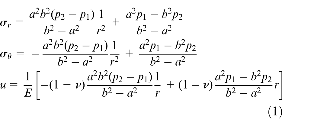
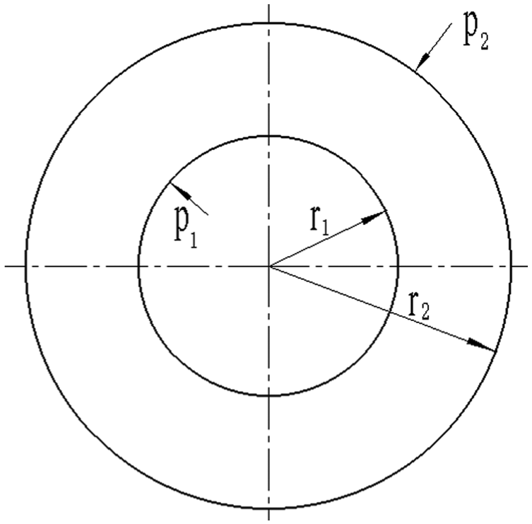
Thick wall cylinder subjected to uniform pressure.
Equations (2)–(8) are deduced from Lame formula to calculate the interference δ2 for the second shrink fitting. The compensation value Δd is obtained according to dimensional deflection of experimentally ironed tooth. The material of outer ring used in this investigation is AISI H13, with a mechanical property of Young’s modulus of 210 GPa and Poisson’s ratio of 0.3. The constants E1, γ1, E2, γ2, E3 and γ3 in equations (2) to (7) represent the Young’s modulus and Poisson’s ratio values of the die insert, inner ring and outer ring, respectively. The schematic diagram of the deformation for each ring is illustrated in Figure 18. Calculation results are listed in Table 4. Consequently, a value of 0.38 mm is calculated as the optimal interference for the second shrink fitting process, which results in the die cavity compensation
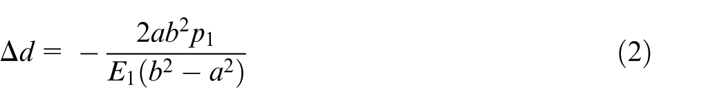
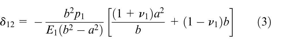
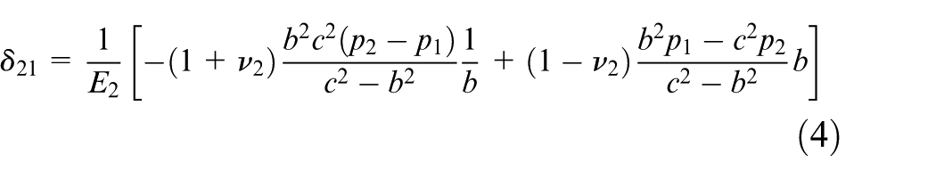

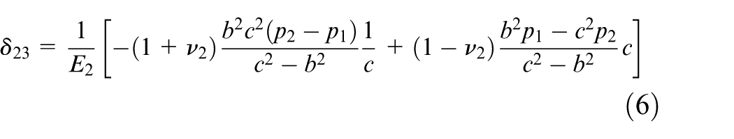
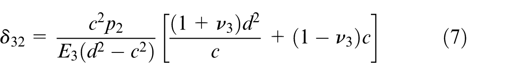


Schematic diagram of deformation for each ring: (a) die insert, (b) inner ring and (c) outer ring.
Manufacture of the spur gear
The ironing die modification and manufacturing for the experiment on the spur gear ironing forming are performed based on the theoretical analysis result. Figure 19 shows the layout of experimental setup for ironing the spur gear. An outer ring is shrink fitted into the initial ironing die with an interference of 0.38 mm. Four test-pieces are used in the ironing operation based on the revised die cavity, and the interference between die cavity and all the test-pieces is 0.1 mm.
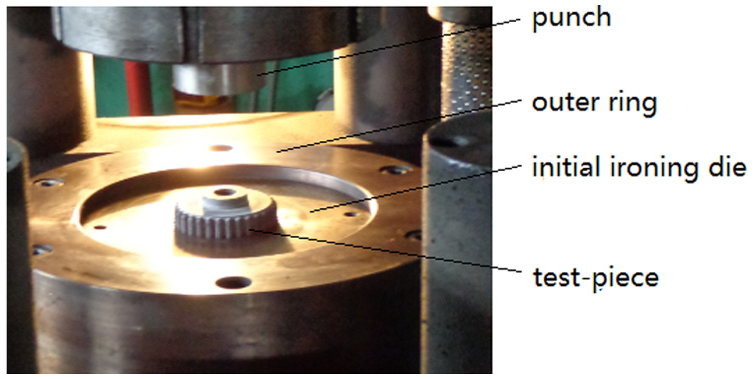
Experimental setup for cold ironing process.
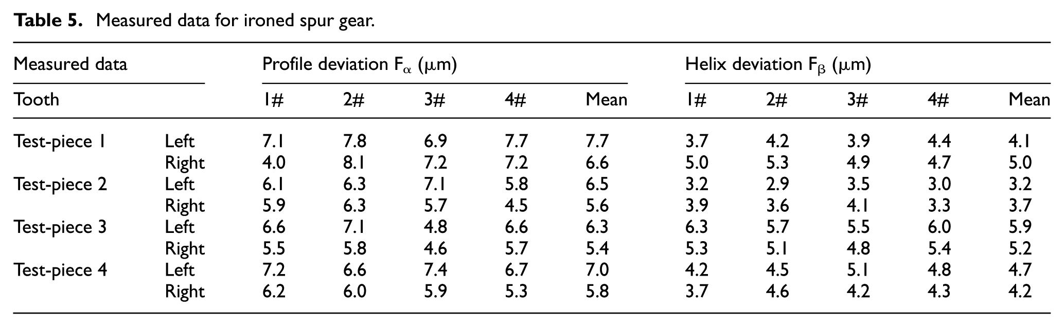
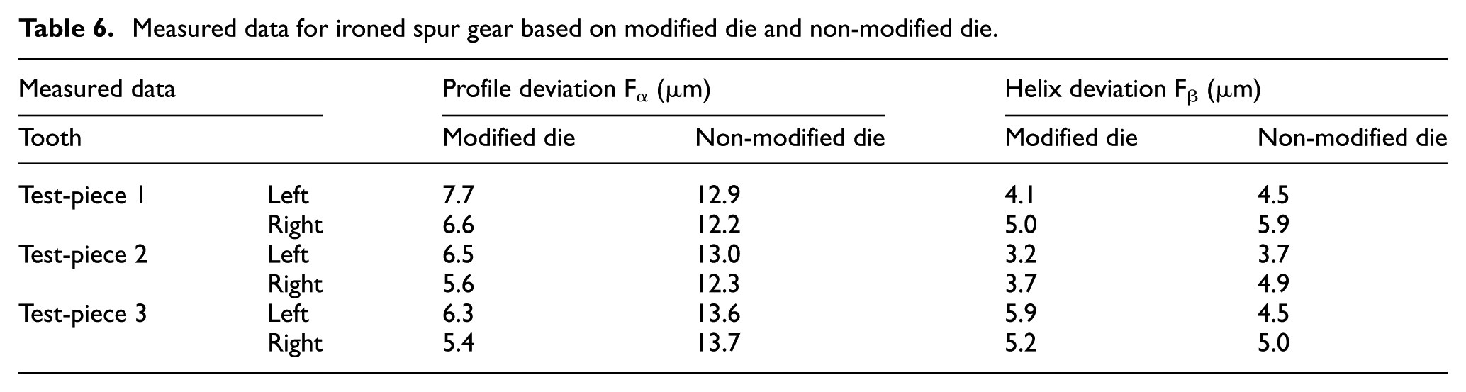
The estimation of the dimensional accuracy of ironed spur gears is shown in Figure 20. Four teeth (both sides) of each test-piece are measured, and the measurement results are shown in Table 5. It is confirmed that all the measured data satisfy the requirements of IOS6 class. Therefore, the validity of the die modification method suggested in this study is demonstrated by experimental result. Table 6 shows the measured data for ironed spur gear based on modified die and non-modified die. It is found that Fα and Fβ values of ironed spur gear are obviously decreased after the die being modified.
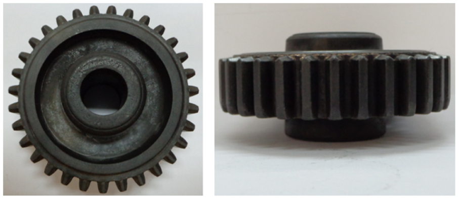
Pictures of ironed spur gear in top view and front view.
Measured data for ironed spur gear.
Measured data for ironed spur gear based on modified die and non-modified die.
Conclusion
As a fundamental research into the elastic characteristic of spur gear and shrink-fitted die for cold ironing process, the experiments and FE simulations are performed to analyze the elastic behavior characteristics of gear and die, the effect of process variable such as the interference between die and tooth on the dimensional errors. A die cavity modification is proposed to improve the dimensional accuracy of final products. The conclusions are summarized as follows:
The elastic deformation behavior of die and tooth in cold ironing process is investigated extensively by FE simulation. It is clear that the elastic behavior of the die and tooth has a significant influence on dimensional accuracy of final products. The dimensional errors induced by die expansion and tooth recovery both increase gradually from base circle to addendum circle in profile direction, when it comes to the vertical direction, the dimensional errors due to die expansion presents a crowned shape, while tooth recovery has little impact on errors.
The characteristics of dimensional errors for cold ironed spur gear obtained numerically and experimentally are similar; the dimensional errors show a tendency of increasing from base circle to addendum circle in profile direction, while dimensional errors in vertical direction give a crowned shape profile. The discrepancy between numerical and experimental results is within the range of 5% relative error.
The effect of interference on profile deviation and helix deviation of the ironed tooth is obtained based on numerical and experimental research. The result of simulation agrees well with that of experiment. The conclusion of that a small interference is advantageous for high dimensional accuracy of final products is reached.
A new die cavity modification method by shrink fitting an outer ring into the initial shrink-fitted die is carried out to improve dimensional accuracy of final products. According to the Lame formula and thick wall cylinder theory, the optimum interference for shrink fitting is calculated. Finally, an experiment based on the modified die is carried out, the measured data reveal that the ironed gear all satisfy the IOS6 class. And Fα and Fβ values of ironed spur gear are obviously decreased. As a result of that, the validity of the die modification method proposed in this study is demonstrated by comparing of experimental results. The cold ironing technology developed in this research to manufacture a spur gear is expected to be useful to other precision parts with a complicated shape.
Footnotes
Declaration of Conflicting Interests
The author(s) declared no potential conflicts of interest with respect to the research, authorship and/or publication of this article.
Funding
The author(s) received no financial support for the research, authorship and/or publication of this article.