
Abstract
Milling head is an essential assembly in the five-axis computer numerical control machine tools, positioning precision of which directly affects the machining accuracy and surface quality of the processed parts. Considering the influence of nonlinear friction in the transmission mechanism and the uncertain cutting force disturbance on the control precision of the milling head, the static and dynamic performances of the milling head are analyzed; relationships among the drive torque, load torque, motion direction and system parameters are discussed; and, finally, nonlinear dynamic model of the milling head is established. A novel adaptive sliding mode control scheme based on the variable switching gain and the adjustable boundary thickness is proposed for this nonlinear dynamic model; the stability of the closed-loop system is guaranteed by the Lyapunov theory. Experimental results show that the proposed adaptive sliding mode control can reduce the chattering in the traditional sliding mode control and can achieve high control precision without knowing the boundaries of uncertainties in advance.
Introduction
Five-axis computer numerical control (CNC) machine tools are widely used in manufacturing the parts of aeronautics and astronautics, the turbine wheels, and some special molds which typically have the complex geometries.1,2 As the key component in five-axis CNC machine tools, the milling head has complex structure, diverse parts and compact transmission, and the system stiffness is difficult to ensure.3,4 Research of the milling head focuses on how to improve the transmission and positioning precision, increase the drive torque and enhance the system stiffness. 5 Recently, all aspects of the system performance have been improved, but there are few successful cases that take all the indicators into account; thus, it is fairly important to improve the positioning precision and driving torque of the milling head simultaneously.6–8
The milling head used for study is mainly based on the worm gear transmission mechanism; compared with the rolling engagement of the traditional gear transmission, engagement of the worm gear is pure sliding. Therefore, the friction influences significantly on positioning precision of the milling head; usually, friction is considered as a kind of interference for the feedback control of the drive system. Additionally, the uncertain cutting load in the machining process affects the dynamic tracking precision; thus, surface finishes of the machined parts will be deteriorated. To maintain the perfect dynamic performance of the milling head during the working process, a controller that is robust to the nonlinear friction and external load disturbance needs to be designed.
Sliding mode control (SMC) has complete self-adaptability to the uncertainties and external disturbances, 9 but the input chattering of SMC will decrease the control precision, improve the energy consumption, stimulate the unmodeled dynamics, deteriorate the system function and even damage the controller parts.10–12 The commonly used methods for chattering elimination are the quasi-SMC and the approaching law.13,14 SMC is proposed in Ganjefar et al. 15 based on the singular perturbation model, which is robust to the time delay. A super-twisting algorithm-based SMC with a nonlinear observer is utilized to operate the vehicles such that a desired wheel slip ratio can be achieved. 16 SMC based on the state and extended disturbance observer is proposed for the mismatched uncertain system, which is validated on flexible joint manipulator. 17 A sliding mode tracking controller with friction compensation is proposed for a precision positioning stage. 18 By designing a sliding surface based on the disturbance estimation, SMC based on nonlinear disturbance observer is developed to counteract the mismatched disturbance. 19 A SMC with perturbation estimation featuring a proportional–integral–derivative (PID)-type sliding surface and adaptive gains is proposed for the control of a micromanipulator with piezoelectric actuation. 20 A robust tracking control based on a hyperbolic tangential SMC and time delay estimation is proposed for a shape memory alloy actuator. 21 An adaptive dynamic surface control combined with the SMC is used to compensate the nonlinear friction and backlash in a linear stage motion system. 22 An integral SMC based on input–output models is proposed for tracking control, and the control chattering is eliminated by selecting an appropriate sliding surface and an integral control action. 23 By designing a nonlinear reaching law based on an exponential function, chattering in SMC is reduced and tracking performance is improved. 24 By analyzing the above control schemes, fundamental reasons for the chattering and low control precision are that the switching gain and the boundary thickness cannot be adjusted. Thus, how to improve the control precision and reduce the chattering is the most important problem.
In this article, static and dynamic performances of the milling head are analyzed; relationships among the drive torque, load torque, motion directions and system parameters are discussed, and, ultimately, nonlinear dynamic model of the system is established. The adaptive sliding mode control (ASMC) is proposed based on the variable switching gain and the adjustable boundary thickness for this nonlinear dynamic model, and the stability of the system is guaranteed by the Lyapunov theory. This control scheme can eliminate the chattering in traditional sliding mode control (TSMC) and can reach a higher control precision without knowing the boundaries of uncertainties. Finally, the validity of the control scheme is verified by experiments.
This article is organized as follows: mechanical structure and control system of the milling head are discussed in section “Mechanical structure and control system of the milling head.” In section “Nonlinear dynamic modeling of the milling head,” nonlinear dynamic model of the milling head is established. The ASMC based on variable switching gain and adjustable boundary thickness is designed in section “Design of the ASMC.” Experiments of the control strategy are carried out in section “Experiments.” The conclusions are drawn in section “Conclusion.”
Mechanical structure and control system of the milling head
The milling head with high power, high torque and high stiffness used for the titanium alloy, superalloy and other difficult-to-cut material processing is illustrated in Figure 1. Backlash of the drive mechanism can be adjusted by the dual lead worm gear, and with a high-resolution encoder mounted on the right side of the shaft, the milling head can be controlled in a closed loop. The hydraulic locking mechanism installed on the left side of the shaft can make the motorized spindle locked at any position in the angle range (−120°, 30°), and control system of the milling head is shown in Figure 2.3,6
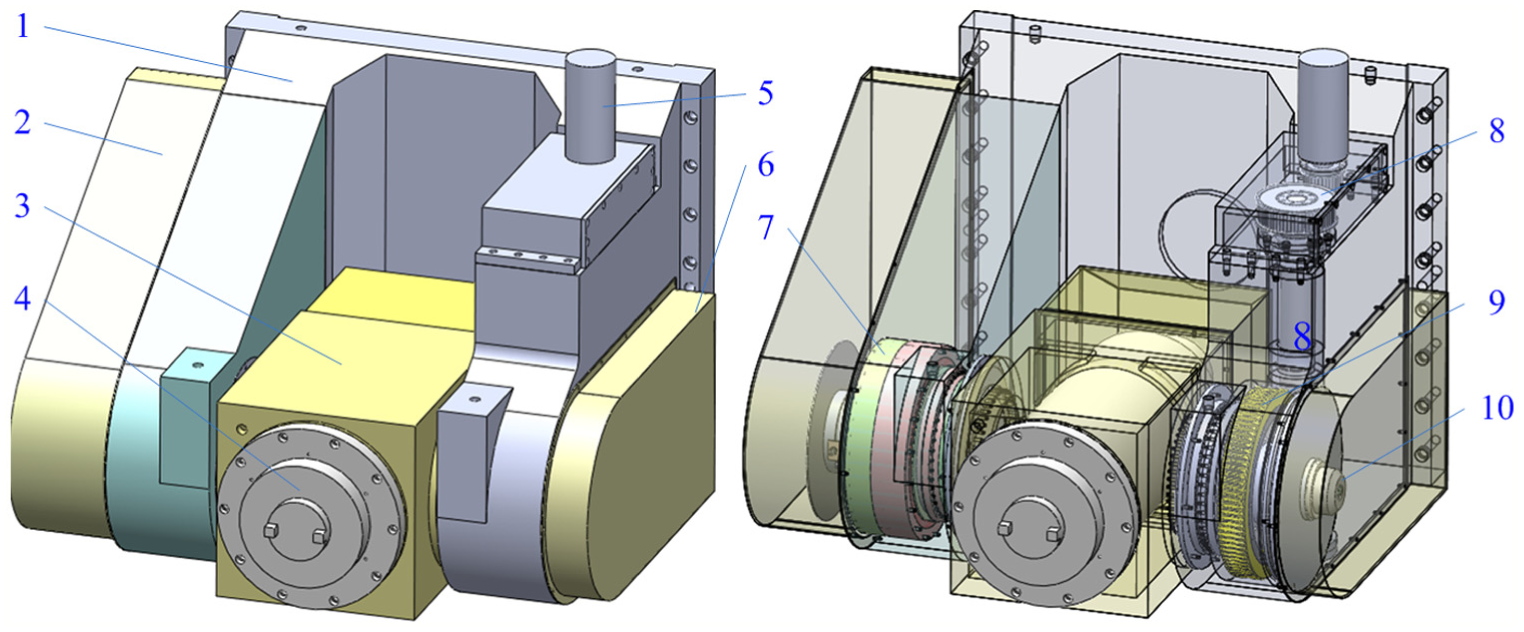
Mechanical structure of the milling head.
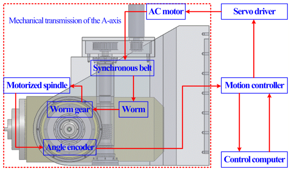
Control system of the milling head.
Nonlinear dynamic modeling of the milling head
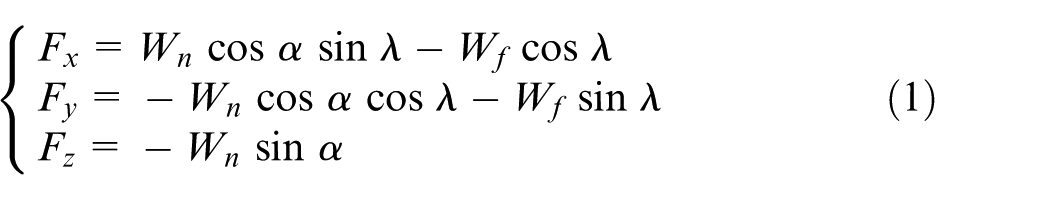
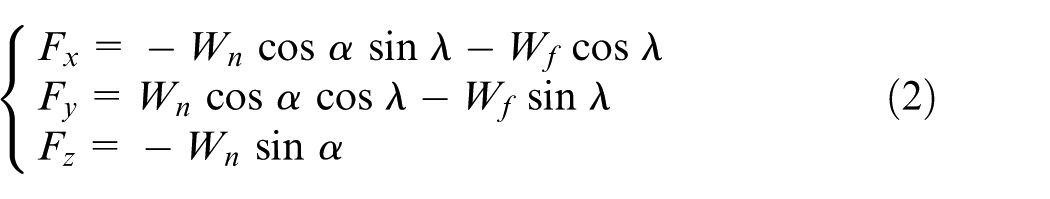
Figures 3 (case A) and 4 (case B) show the force exerted on the right side and left side of the worm, respectively. τb is the input torque exerted on the worm, and τl is the load torque imposed on the gear. The forces exerted on the worm include the normal force Wn and the friction Wf (Wf = µWn). Wf is tangent to the pitch helix, Wn is vertical to the pitch helix and the normal pressure angle is α. The gear shaft and worm shaft are parallel to the x-axis and y-axis, respectively. According to the definition of the coordinate system, the lead angle λ is between Wf and the x-axis. Forces exerted on the worm can be decomposed into three vertical forces Fx, Fy and Fz.25,26
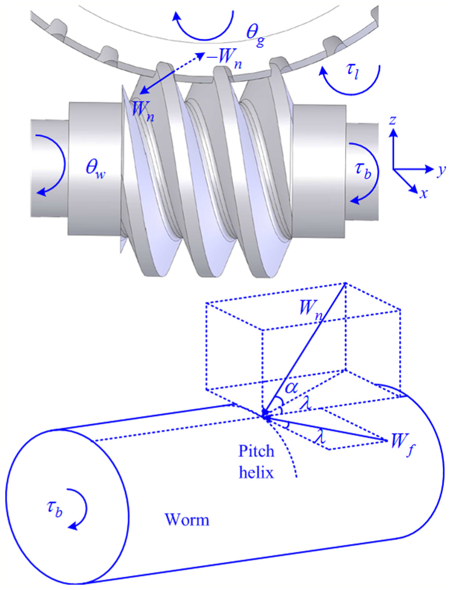
Force exerted on the right side of the worm.
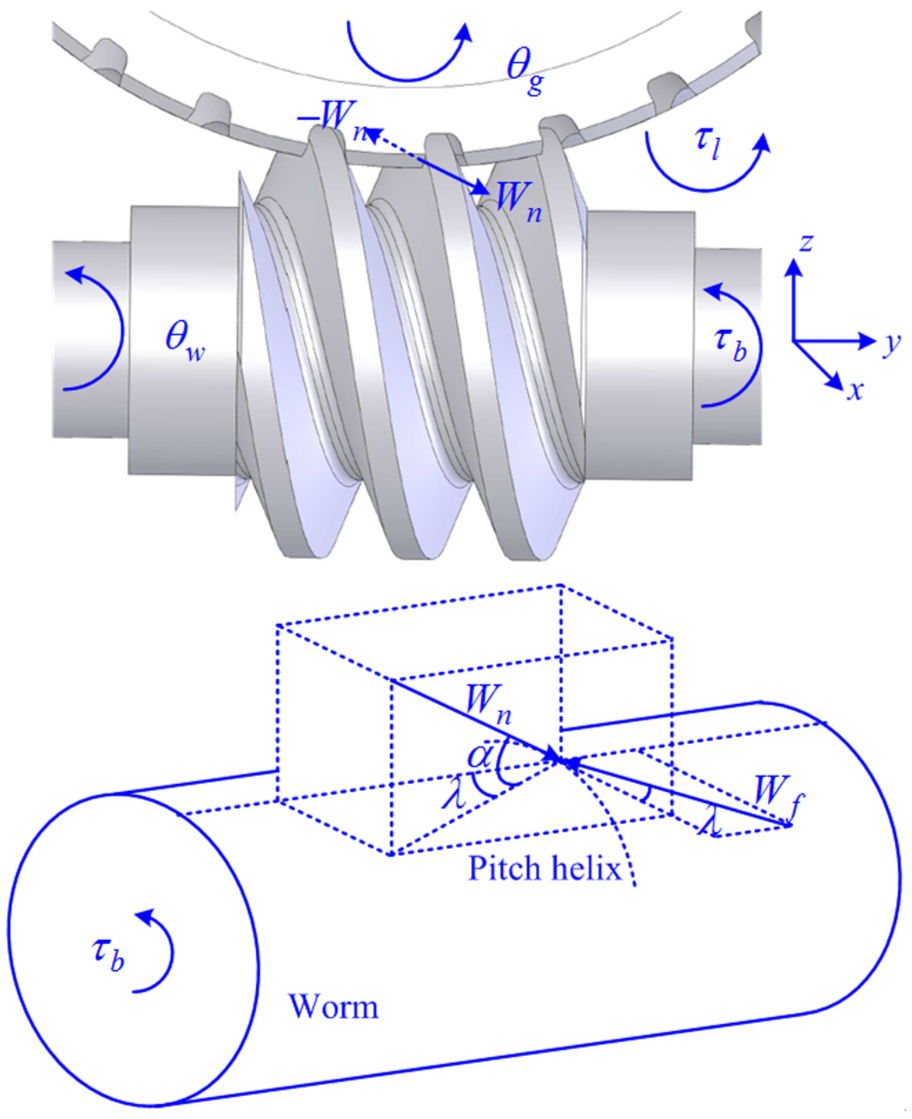
Force exerted on the left side of the worm.
For case A
For case B
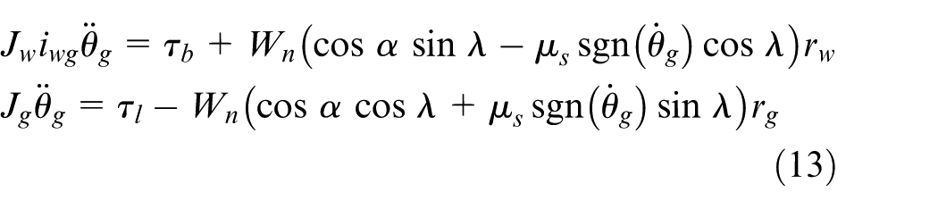
From Figure 3, dynamic equations of the worm and the gear can be expressed as follows
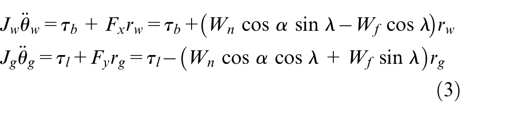
where θw (θg), Jw (Jg) and rw (rg) are the rotation angle, the equivalent inertia and the pitch circle radius of the worm (gear), respectively.
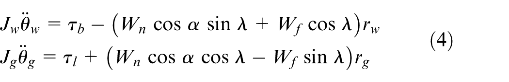
Similarly, the following dynamic equations can be derived according to Figure 4
Static analysis
For case A, if
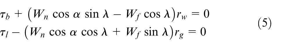
Substitute Wf = µWn into equation (5), then
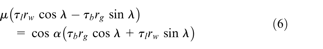
Since 0 < cosα < 1, suppose τlrw cosλ − τbrgsinλ = 0, and there must be

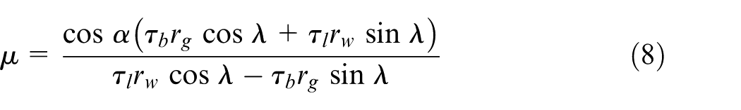
Since 0 < sinλ < 1, 0 < cosλ < 1, rg > 0 and rw > 0, thus τb = τl = 0. To make τlrw cosλ − τbrgsinλ ≠ 0, there should be τb ≠ 0 and τl ≠ 0. If τb = τl ≠ 0, tan λ = −(rg/rw) < 0 can be derived by equation (7), and this is contradictory to 0 < λ < π/4. Therefore, in order to make τlrw cosλ − τbrgsinλ ≠ 0, then there must be τb ≠ τl ≠ 0. Then, the following can be derived by equation (6)
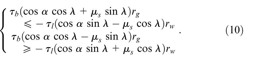
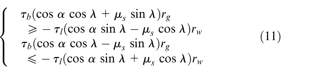
Considering −µsWn ≤ Wf ≤ µsWn, in which µs is the coefficient of static friction. Thus
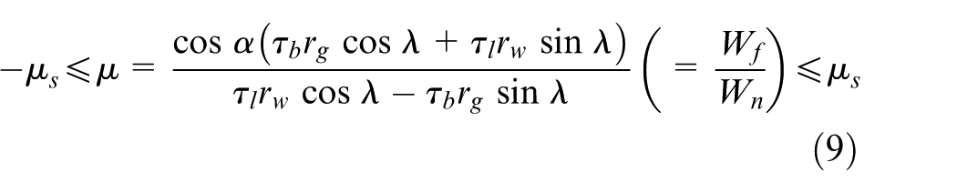
Next, to make the system remain stationary, the relationship between τb and τl in equation (9) will be discussed:
1. When τb < τl(rwcosλ)/(rgsin λ)
2. When τb > τl(rwcosλ)/(rgsinλ)
To simplify the discussion, define the following parameters:
1.µw ≤ µs ≤ µg: in this case, C1 ≤ 0 and C2 ≥ 0. When τb and τl satisfy the following conditions, equation (9) will be obtained
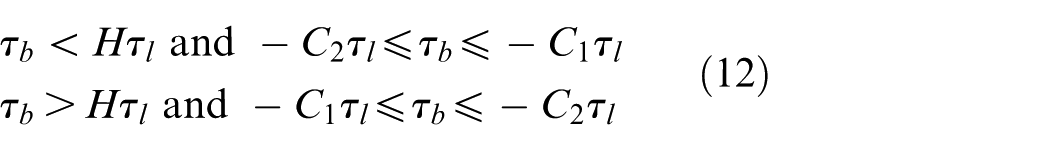
To keep the system moving under the constraint conditions, if τb < Hτl (τb > Hτl), and when the starting torque τb is −C1τl (−C2τl), the system will keep a positive movement, and when τb is −C2τl (−C1τl), the system will keep a negative movement. The above two constraints can be illustrated in Figure 5(a); equation (12) can be represented as the shaded part, and the system is static. In this case, when τb = 0, no matter how much τl is, the drive system will remain static. This is called the gear self-locking.
2.µg < µs: in this case, C1 < 0 and C2 < 0. When τb and τl are in the shaded part of Figure 5(b), equation (9) will be obtained. When τl = 0, no matter how much τb is, the system will remain static. This is called the worm self-locking. Because τb cannot overcome the static friction and keep the system moving, this design does not exist in practice.
3.µs < µw: in this case, C1 > 0 and C2 > 0. When τb and τl are in the shaded part of Figure 5(c), equation (9) will be obtained. In this case, neither the worm nor the gear will be in the self-locking state.
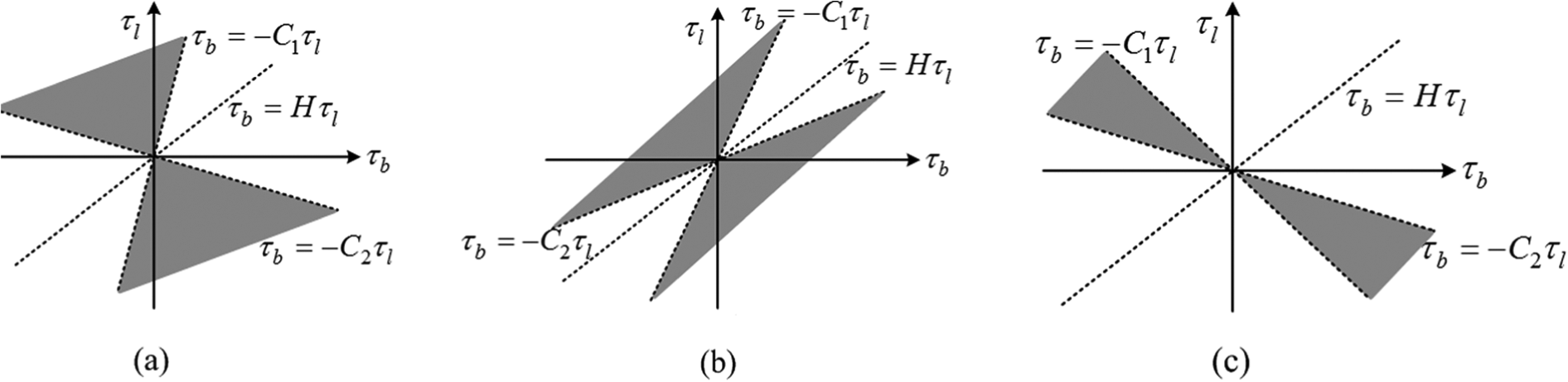
Relationship between τb and τl in the static state: (a) µw ≤ µs ≤ µg, (b) µg < µs and (c) µs < µw.
Analyze the case B according to equation (4), and the similar conclusions will be derived. The gear self-locking is often utilized in practice, which can sustain any static load torque without driving. Next, we will mainly discuss this case.
Dynamic analysis
For case A, assume that there is no backlash in the system, and the transmission ratio is iwg; thus, θw = iwgθg. Suppose the coefficients of static and dynamic frictions are the same, the following can be derived by equation (3)
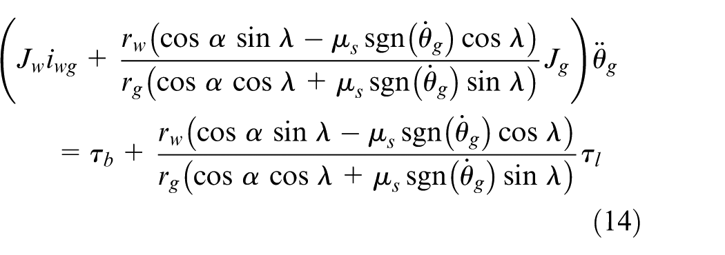
Eliminate Wn in equation (13), and the following equation can be derived
When
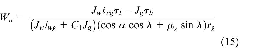
Since Wn > 0, the system will switch from case A to case B when Wn ≤ 0, and equation (15) will be discussed as follows:
1. When τb ≤ (Jwiwgτl)/Jg and C1 ≥ −(Jwiwg)/Jg, the following can be derived from equation (14)

2. When τb > (Jwiwgτl)/Jg and C1 < −(Jwiwg)/Jg, the following can be derived from equation (14)

For τl = 0 and τb > 0, since Jwiwg + C1Jg < 0, the direction of the acceleration is contrary to that of the input torque in equation (17), which is obviously unreasonable. The system will switch from case A to case B when this case occurs.
When
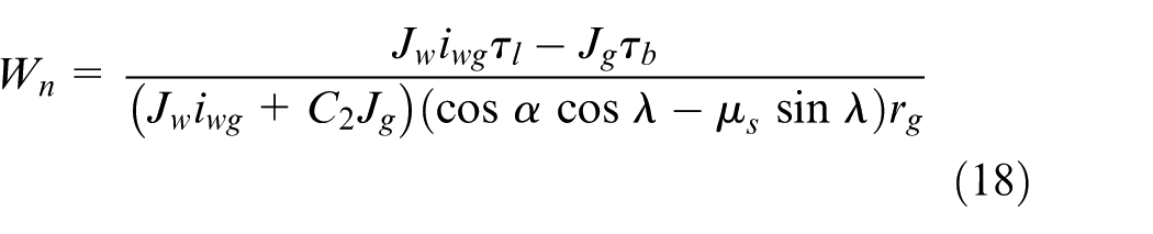
Since Wn ≥ 0 and cosαcosλ − µssinλ ≥ 0 under the condition µw ≤ µs ≤ µg, equation (18) will be discussed as follows:
3. When τb ≤ (Jwiwgτl)/Jg and C2 ≥ −(Jwiwg)/Jg, the following equation can be derived from equation (14)

4. When τb > (Jwiwgτl)/Jg and C2 < −(Jwiwg)/Jg, the following equation can be derived from equation (14)

For τl = 0 and τb > 0, since Jwiwg + C2Jg < 0, the direction of the acceleration is contrary to that of the input torque in equation (20), which is obviously unreasonable. The system will switch from case A to case B when this case occurs.
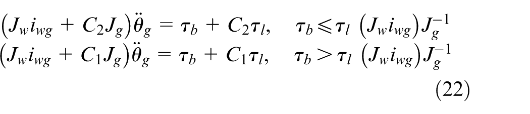
Similar equations can be derived from case B, and the following can be obtained by the above discussion:
When
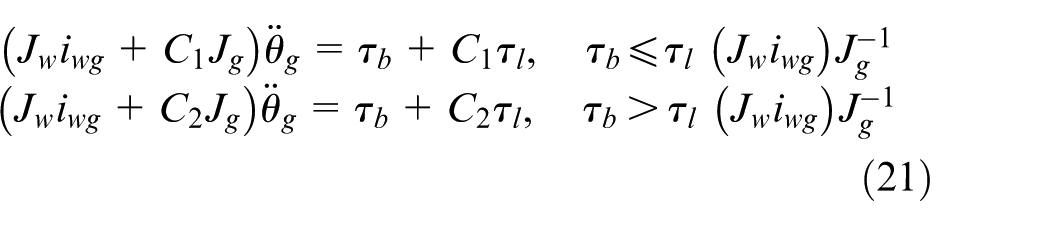
When
Extend the above dynamic equations, and dynamic model of the milling head can be derived as followsz
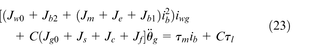
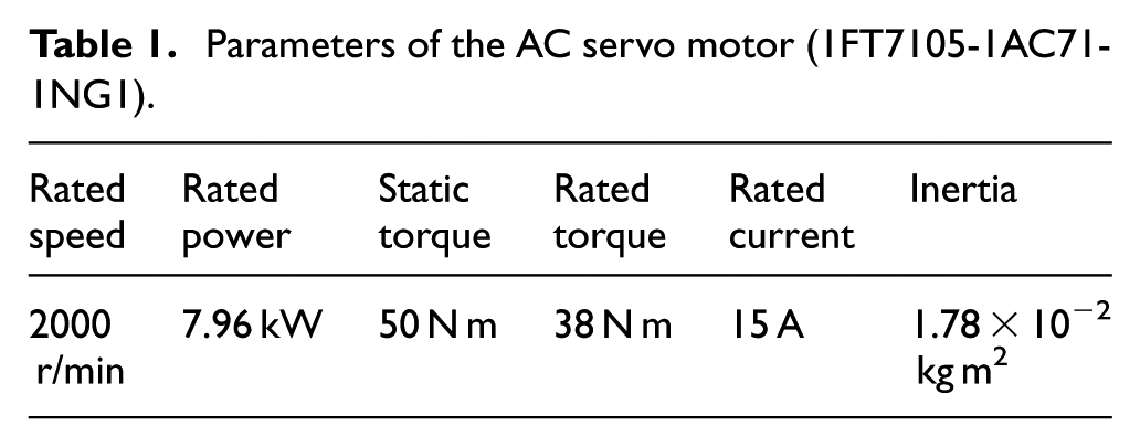
where Jw0, Jm, Je, Jb1 and Jb2 are the inertias of the worm, motor, expansion sleeve, small pulley and big pulley, respectively. Jg0, Js, Jc and Jf are the inertias of the gear, motorized spindle, support shaft and fixed portion of the braking mechanism. τm is the motor torque, ib is the transmission ratio of the timing belt, where Jw0 =97.29×10⁻⁴kgm2, Jb2=194.34 ×10⁻⁴kgm2, Jm=178×10−4kgm2, Je=8.79×10⁻⁴kgm2, Jb1=11.46× 10⁻⁴kgm2, ib=2, iwg=90, Jg0 =790.80×10⁻⁴kgm2, Js=6.60kgm2, Jc=5253.68×10−4kgm2 and Jf=1890 ×10−4kgm2.
Design of the ASMC
TSMC
Considering the following n-order single-input and single-output (SISO) uncertain nonlinear system 27

where x ∈ R is the system output, u ∈ R is the control input,
Define e = x − xd is the tracking error, and the error vector is
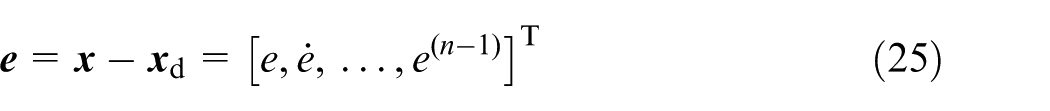
Sliding surface is defined as follows

where
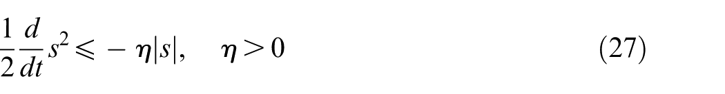
The sliding motion includes the reaching phase (s ≠ 0) and the sliding phase (s = 0), and the SMC can guarantee the system convergence, that is, when t → ∞, e(t) → 0.
For the system (24), the control law (28) can satisfy the condition (27) if f(
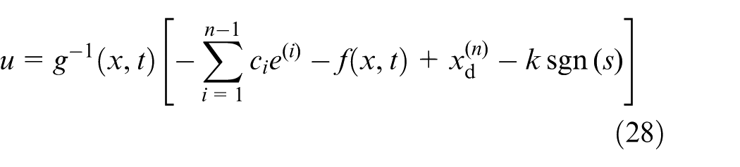
where switching gain k > 0 is a constant.
ASMC based on the bipolar sigmoid function
To achieve a balance between the control precision and the chattering, the bipolar sigmoid function–based ASMC is proposed, which can be derived from equation (28)
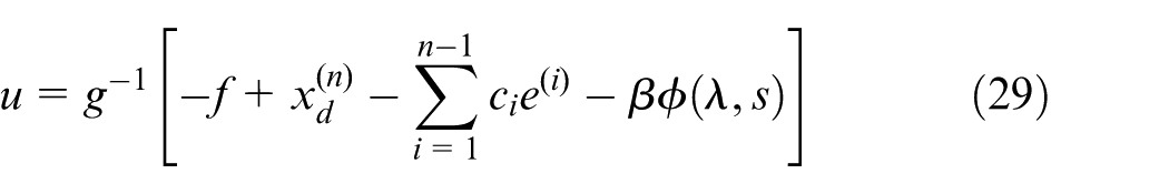
where
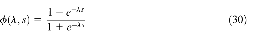
β and λ are the parameters that can be adjusted. Steepness of
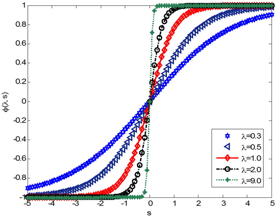
Bipolar sigmoid function.
For β and λ, the following adaptive laws are designed
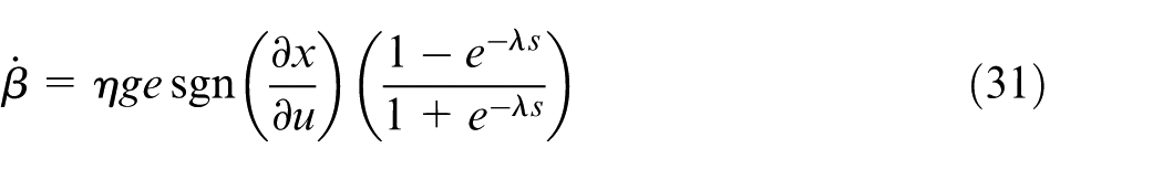
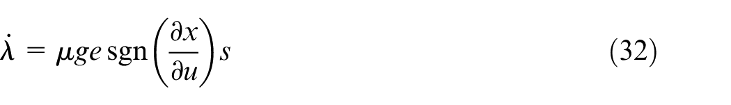
where η > 0 and µ > 0 are the adjustment rates.
Theorem
Under the action of the sliding surface (26) and the control law (29), the adaptive laws (31) and (32) can guarantee the system (24) stable, and ultimately, the chattering and tracking error can be eliminated.
Proof
Define the Lyapunov function as V = e2/2
Based on the chain-type derivation method
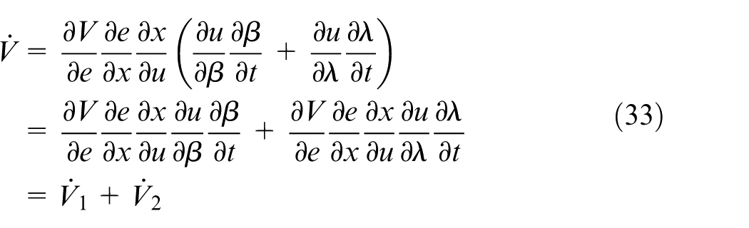
Substitute equation (29) into equation (33)

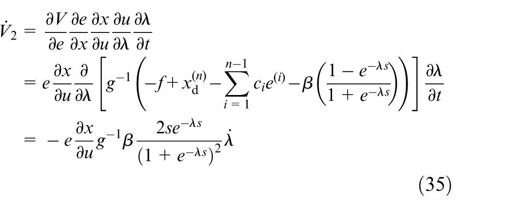
Substitute equations (31) and (32) into equations (34) and (35), respectively, then
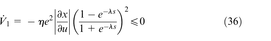
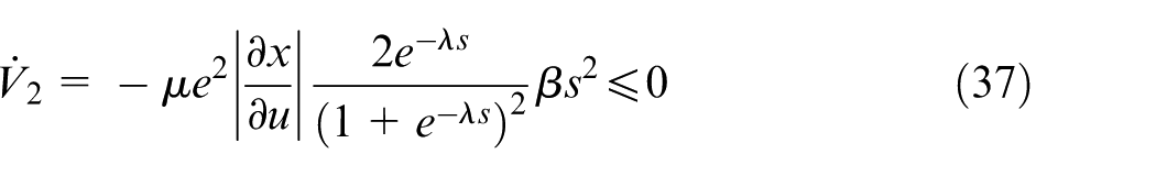
Since
Experiments
Experimental verification of the proposed control algorithm is carried out based on the milling head presented in section “Mechanical structure and control system of the milling head.” ADVANTECH IPC-610-H is used as the host computer which is employed to edit and execute the control programs, achieve human–computer interaction and control various motions of the milling head via the motion controller. PMAC2A PC-104 is adopted as the slave computer which is employed to drive the AC motor to complete the desired motions and monitor the state variation and edit the control programs in the C++, which includes the PID control, TSMC and ASMC, conversion programs of the analog-to-digital (A/D) and digital-to-analog (D/A), sampling program and measurement program. PEWIN32 PRO is utilized to compile the edited program, and the compiled machine code is downloaded into RAM of the PMAC; then, use the command SAVE to copy the program to the flash memory. When the system is power on or reset, the control program will be automatically downloaded from the PMAC, and the user-defined control algorithm will become the firmware program of PMAC. The data acquisition, conversion and output will be carried out by the acquisition card (ADVANTECH PCL818L), the isolated digital card (PCL730) and the analog output card (PCL726).
From equations (21) and (22), the general form of the equation is
To design the SMC, a new control input u is introduced, where
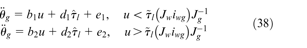
where
The torque sensor (Kistler 4504B × B1P) is used to test τl, and another torque sensor (HBM T10F) is used to test τm; thus, τb = τmib, and the installation positions of the torque sensors are shown in Figure 7. Experiment scheme is shown in Figure 8; a metal block whose mass is m is fastened at the end of the motorized spindle to simulate the cutting force. From Figure 8,
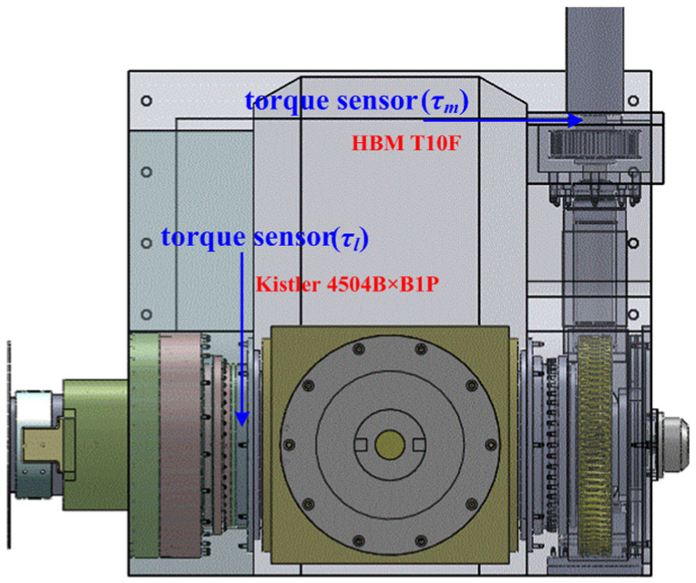
Installation locations of the torque sensors.
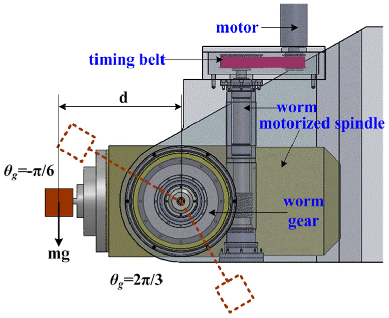
Diagram of the experiment scheme.
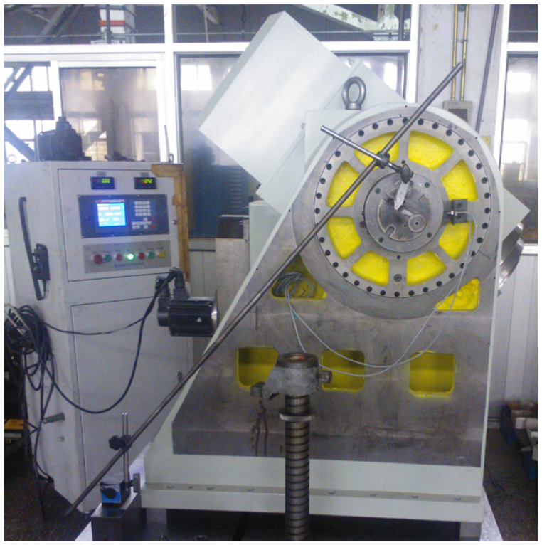
Experimental equipment of the milling head.
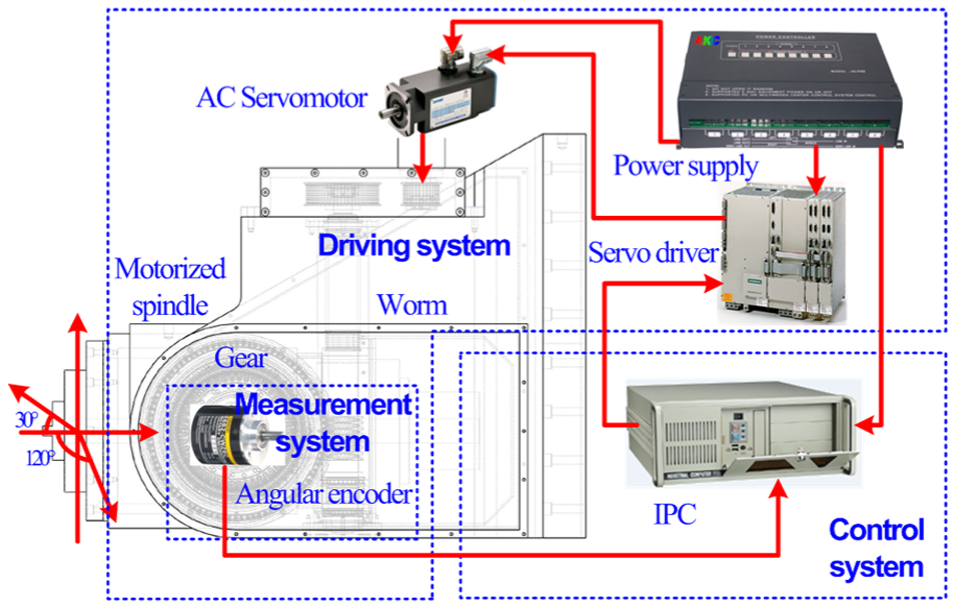
Control system diagram of the milling head.
Parameters of the AC servo motor (1FT7105-1AC71-1NG1).
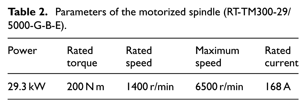
Parameters of the motorized spindle (RT-TM300-29/5000-G-B-E).
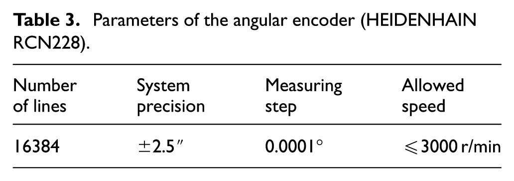
Parameters of the angular encoder (HEIDENHAIN RCN228).
Control objective of the milling head is to design a perfect controller that is robust to the uncertain control gains b1 and b2 and the uncertain load disturbances
First, the experiments of the traditional PID control is carried out, selecting θd(t) = 0.5sin(πt) rad, kp = 20, ki = 0.01, kd = 5 and
Experiments based on the traditional PID control: (a) position tracking and tracking error and (b) control input.
Second, control performance of TSMC is verified, selecting θd(t) = 0.5sin(2πt),
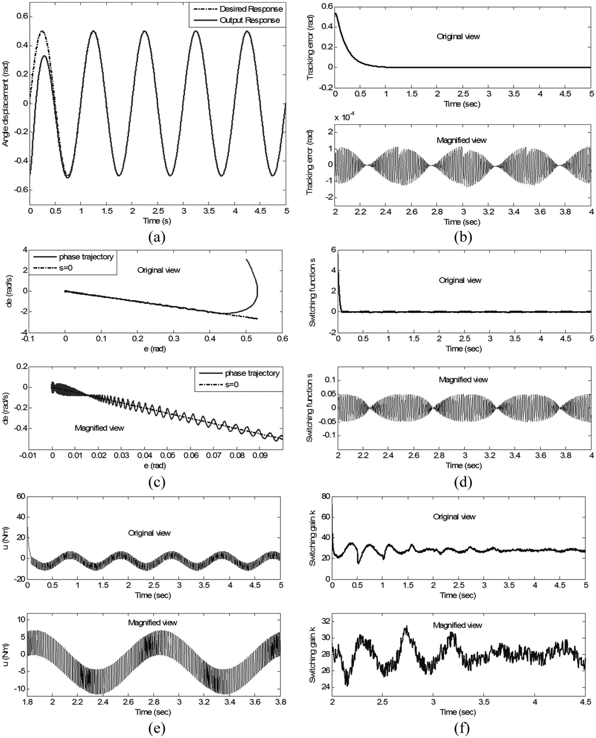
TSMC based on sgn(s): (a) position tracking response, (b) position tracking error, (c) phase trajectory, (d) switching function, (e) control input and (f) variation of k.
To reduce the input chattering of TSMC, use the saturation function to replace the sign function. From Figure 13(a) and (b), the tracking error of TSMC based on sat(s, ϕ) is 1.863 × 10⁻⁴ rad, compared with PID control, and it reduced to 24.33%. When compared with TSMC based on sgn(s), the tracking error increased to 38.10%, but the input chattering has been reduced significantly, as illustrated in Figure 13(e); the phase trajectory in Figure 13(c), the switching function in Figure 13(d) and the variation of k in Figure 13(f) also indicate that TSMC based on sat(s, ϕ) can effectively reduce the chattering.
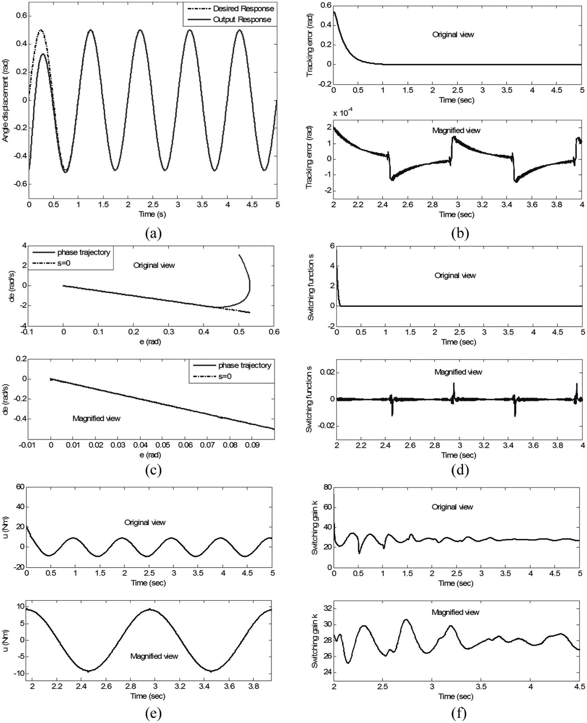
TSMC based on sat(s, ϕ): (a) position tracking response, (b) position tracking error, (c) phase trajectory, (d) switching function, (e) control input and (f) variation of k.
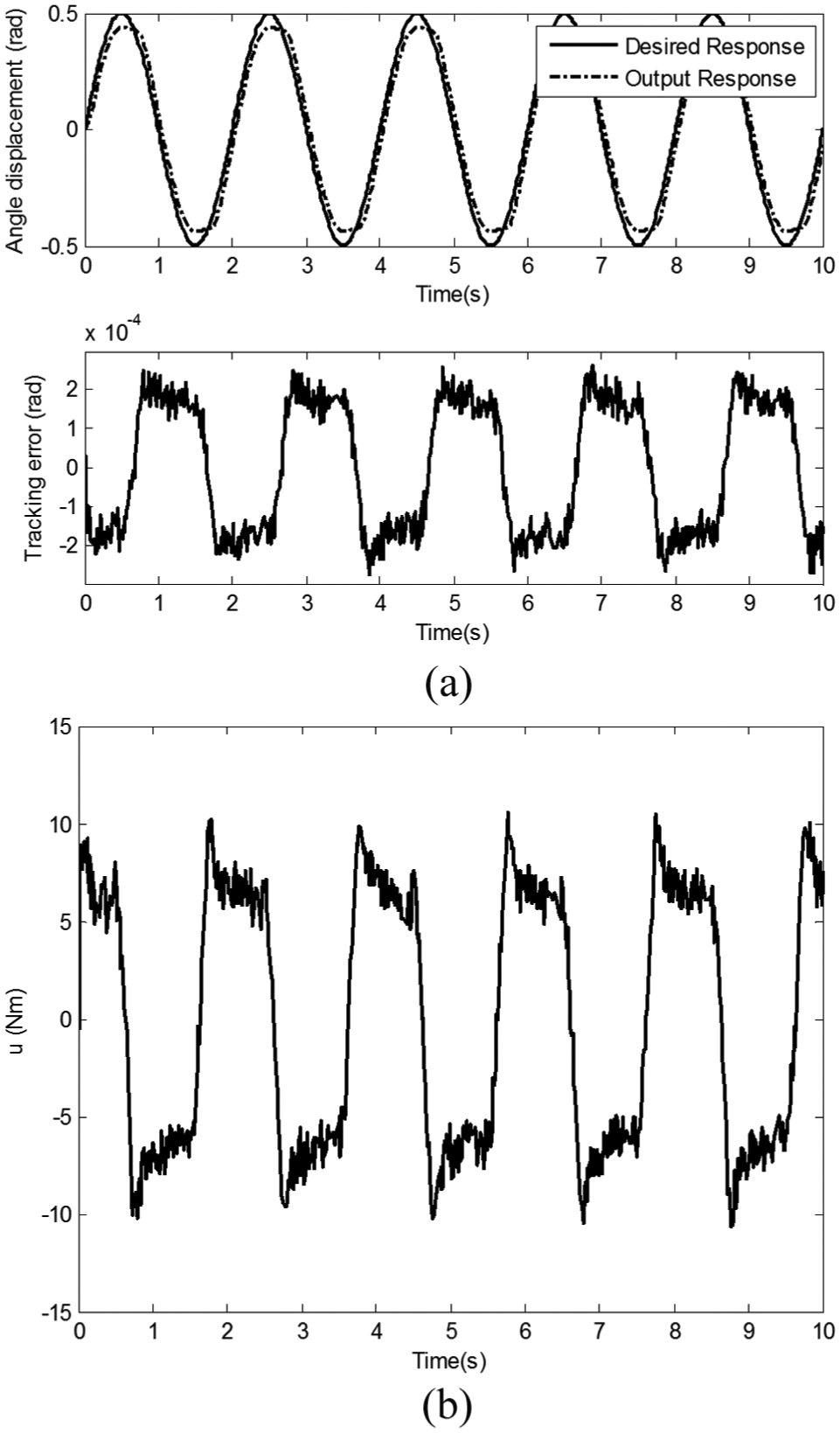
Third, implement the experiments of ASMC; select δ(0) = 60, ξ(0) = 5, η = 50 and µ = 20; and employ the control law (29) and the adaptive laws (31) and (32). Experimental results are illustrated in Figure 14.
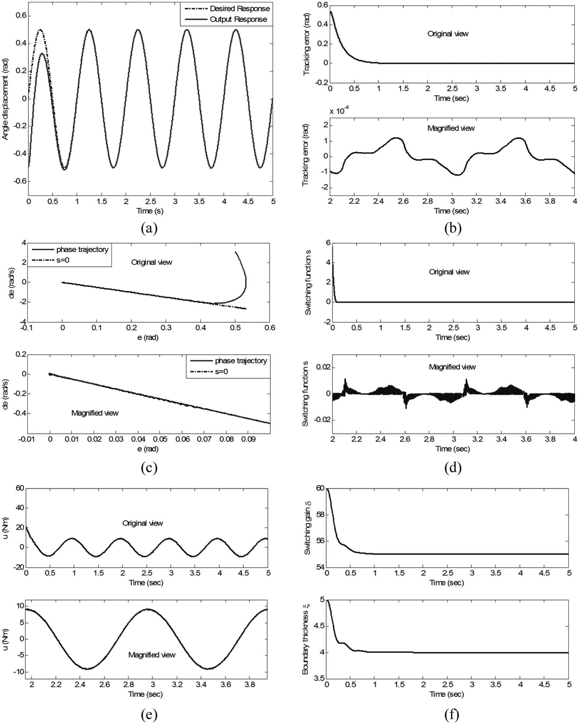
Experiments based on ASMC: (a) position tracking response, (b) position tracking error, (c) phase trajectory, (d) switching function, (e) control input and (f) variations of δ and ξ.
From Figure 14(a) and (b), the tracking error of ASMC is 1.215 × 10⁻⁴ rad, and compared with the PID control, TSMC based on sgn(s) and TSMC based on sat(s, ϕ), the tracking error of ASMC has been reduced to 50.6%, 9.93% and 34.8%, respectively. Simultaneously, input chattering of ASMC has been reduced significantly, as illustrated in Figure 14(e); the phase trajectory in Figure 14(c), the switching function in Figure 14(d) and the variation of k in Figure 14(f) also indicate that ASMC can effectively reduce the chattering, and ASMC does not need to know the uncertainties boundaries in advance. Switching gain and boundary thickness can be adjusted to the desired values adaptively according to the actual situation. As shown in Figure 14(f), the ideal values are δd = 54.88 and ξd = 4.012. Chattering and tracking error are affected by the initial values of δ, ξ, η and µ, and these values should be tuned repeatedly till the system can obtain perfect performance.
In summary, for TSMC based on sgn(s), when the system trajectory reaches the sliding surface, moving points on the trajectory can pass through the sliding surface under the function of inertia; finally, the chattering generates and superposes on the ideal sliding mode. For the actual computer control system, high-speed logic conversion and high-precision numerical calculation make the influence of time and space lag of the shifting switch is almost zero; therefore, discontinuity caused by the switching operation is the essential reason for the chattering generation.
For TSMC based on sat(s, ϕ), the SMC is adopted outside the boundary and the continuous control is employed in the boundary; in this way, the chattering can be reduced effectively. The thinner the boundary, the better the control performance; however, the control gain will become larger, and the chattering will become more severe and vice versa.
To achieve a balance between the control precision and the chattering, the bipolar sigmoid function–based ASMC is proposed, β and λ are the parameters that can be adjusted according to equations (31) and (32). From Figure 6, the larger the λ, the steeper the
Conclusion
The milling head with high power, high torque and high stiffness used for processing the titanium, superalloy and other difficult-to-machine materials is presented in this article. First, statics and dynamics of the milling head are analyzed; relationships among drive torque, load torque, motion direction and system parameters are discussed; and nonlinear dynamic model of the system is established. Second, for this model, a novel ASMC based on the variable switching gain and the adjustable boundary thickness is proposed, and the system stability is guaranteed by the Lyapunov theory. Experimental results show that the designed control scheme is robust to the uncertain load and parameter perturbation, and it not only can improve the control precision but also can reduce the input chattering.
Footnotes
Appendix 1
Declaration of conflicting interests
The author(s) declared no potential conflicts of interest with respect to the research, authorship and/or publication of this article.
Funding
The author(s) disclosed receipt of the following financial support for the research, authorship, and/or publication of this article: This work was supported by the National Natural Science Foundation of China (no. 51505356) and the Fundamental Research Funds for the Central Universities of China (nos XJS14043 and JB150409).