
Abstract
Casting simulation softwares are increasingly being used in modern foundries and metal casting industries. Softwares simulate the casting process in a virtual domain and provide insight into mold filling, solidification and cooling, and casting defects. Casting simulations allow designers to model, verify, and validate the process followed by optimization of design and process parameters before they actually put into practice. This article aims at exploring the methods of modeling and simulation of metal casting processes with reference to some related case studies. Most commonly available casting simulation softwares and the underlying mathematical models used are briefly introduced. Casting process simulation together with the results obtained is well explained. Case studies from the literature revealed that simulation tools are playing a vital role in producing high-quality defect-free cast products by providing an in-depth understanding of mold filling and solidification, gating, runner and feeding system design, and other process parameters. Recent efforts on integrating the casting simulations to mechanical performance simulations are discussed which is quite promising in predicting the service life of cast products. It is concluded that simulations have been well established in metal casting processes and more developments in simulation tools are needed for reliability prediction of castings.
Introduction
The use of computational methods and numerical simulations in metal casting has become a powerful tool to analyze mold filling, solidification, and cooling, and to envisage the location and type of internal defects. 1 These simulation methods allow modern foundries to shift from conventional “trial-and-error” to “proof-of-concept” approach in product development paradigm. The shift from heuristic know-how and experimental means to more scientific simulations enabled researchers and foundrymen to analyze entire casting process and the dynamic behavior of a casting system during working conditions. 2 Increased market demands for minimum design and production lead times, high-dimensional accuracy, modern and difficult to cast designs and processes, and improved product quality lead to computationally design a casting process which can eradicate all bottlenecks as observed in a traditional cast product development. Computer-aided design/computer-aided manufacturing (CAD/CAM) coupled with casting industry standards partially removes these bottlenecks by reducing time and cost in product development. However, CAD/CAM does not address all the issues such as defect predictions and minimization by comparing alternative mold designs with the initial mold design (based on standards). Such comparison of alternative molds allows to develop a design in virtual domain which also optimize the yield (weight of a casting divided by the weight of the metal poured to produce the casting) of casting process. Casting simulations, on the other hand, not only allow researchers to model, verify, and validate the process, but also to optimize the design and process parameters before they actually put into practice in a foundry. Due to these capabilities, these simulations are now viewed as most technologically efficient and economical method for cradle to grave analysis of cast products.
A host of physical processes such as all modes of heat transfer (conduction, convection, and radiation), mass transfer (primarily fluid dynamics), phase transformations during solidification and post-solidification stages, and stress–strain behavior of the cast products 3 has to be well understood and modeled in development of any casting simulation software. The underlying physics of the casting (heat and mass transfer) and their mathematical models, for example, conservation of mass, momentum, and energy along with accurate database of material properties and other physical properties and model parameters related to cast metals and mold materials are integrated in any simulation software. 4 A variety of methods for solving mathematical equations are available, and the most common of which are finite difference method (FDM), finite volume method (FVM), finite element method (FEM), vector element method (VEM), cellular automation (CA) method, and so on.3,5 In some instances, a combination of two or more techniques may also be employed, the examples of which are cellular automation finite element (CAFE) method proposed by Rappaz and Rettenmayr, 6 and a hybrid method for casting process simulation by combining FDM and FEM. 7 The final simulation results, however, are representative of casting process and properties, qualities and defects of cast products irrespective of the type of solutions discussed above. It is reported that these upfront design considerations and casting simulations are important due to the fact that 20% of these activities at the upfront design level leads to about 80% of cost and quality issues of cast products. 8 Moreover, errors in design phase and production phase share 90% and 10% of the casting defects, respectively, 9 due to which “right design at the first time” and reduced physical trial-and-error approach must be emphasized for any casting process.
With continuous developments in casting simulation tools, they are now being utilized in a range of stages of product development such as casting design, process determination, flow pattern, design of tooling, quality control, product stress analysis, to name a few. Casting design is important as it influences all subsequent stages of product development. Computer-aided casting designs allow for optimum casting geometries and features, which can be confirmed by filling simulation, solidification analysis, and stress distribution within the cast product.10,11 From process determination perspective, the flow characteristic in a mold is revealed and subsequent solidification behavior can be analyzed, which confirms the optimum mold design, appropriate process routing, and process parameters.12–19 Defect minimization and quality improvements are also possible by simulating and viewing the filling and solidification behavior and understanding the underlying factors affecting product quality and mechanisms of defect formations.20–27
This study provides insights on how casting simulation softwares have found increasing use in modern casting foundries to produce defect-free castings for their end use, and what are the new trends in this direction. Methods of modeling and simulation of metal casting processes along with some related case studies are reviewed. Most commonly used casting simulation tools are discussed in section “Casting simulation softwares.” Section “Mathematical modeling in a casting simulation software” reflects on mathematical modeling of casting phenomena. The details of modeling and simulation of metal casting processes are explained in sections “Casting process simulation” and “Casting simulation results,” respectively. Section “Case studies using casting simulation tools” includes case studies on casting processes, first simulated, and then optimized by modifying casting design and process parameters. Conclusions and recommendations are summarized in the final section of the article.
Casting simulation softwares
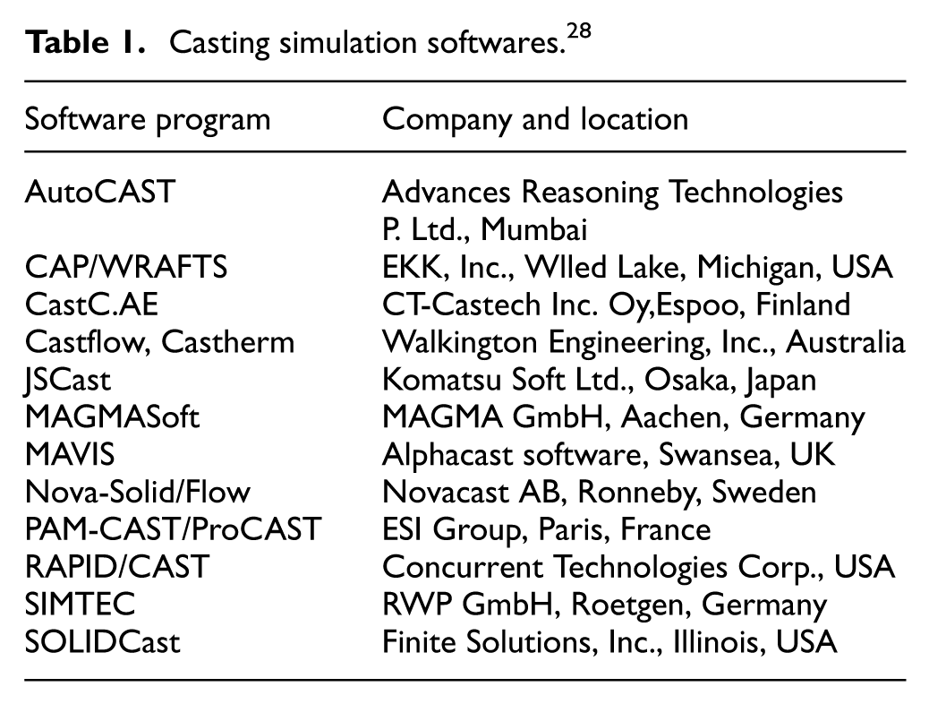
Modeling and simulation of casting processes are found to be a tricky exercise due to a host of parameters associated with it, such as fluid velocity, pressure, geometry of the mold, gating and runner system. Taking into account all important factors that can directly and indirectly influence the metal casting process is a key to develop a casting simulation software. A range of casting softwares that have been emerged over time are a result of understanding the physical phenomena during a casting process. The relevant mathematical models are either developed or modified and then implemented/coded into computer programs to develop a software. 28 Table 1 summarizes some of the most commonly used casting simulation softwares that are currently available to researchers and foundrymen. Figure 1 depicts the user interfaces of some of these softwares where the presentation of results is not much different from one simulation package to another. Some of the mathematical solutions that are utilized in these simulation softwares are FDM, FVM, FEM, VEM. Although the underlying physics is same, these techniques differ in discretization of space and time continuum, treatment of material properties, boundary conditions, and the numerical method applied for solving the problem. 29 For example, FDM and FVM discretize the domain using tetragonal or hexagonal elements, whereas VEM uses a combination of cubic and pyramid elements. Moreover, modeling casting shapes is easy using FEM, but it requires more efforts in meshing, thereby increases computational time.
Casting simulation softwares. 28
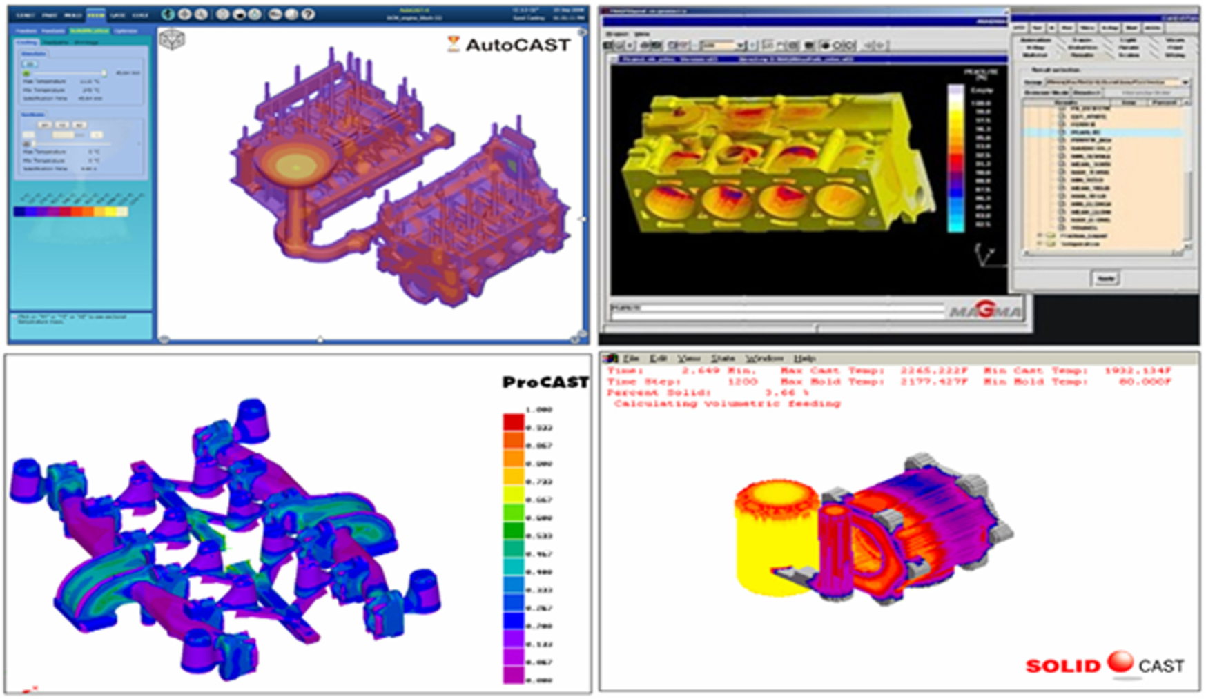
User interface of common casting simulation softwares (AutoCAST, MAGMA, ProCAST, and SolidCAST). 29
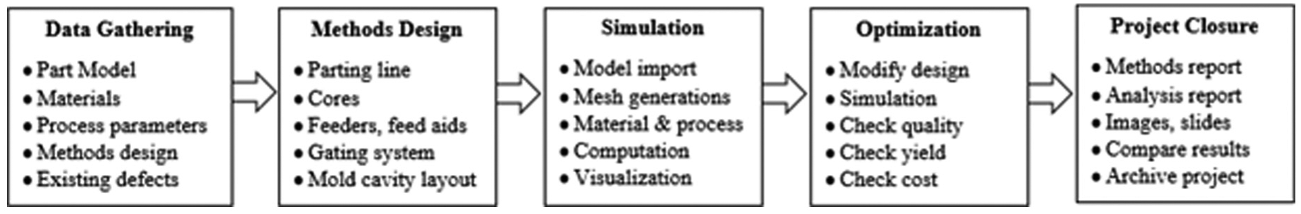
A casting simulation project using commercial softwares is generally composed of five stages as shown in Figure 2. These five stages are data gathering, methods design, numerical simulation, methods optimization, and project conclusions. 29 Data gathering refers to all needed information related to CAD model of casting, cast metal properties, mold properties, process parameters. Methods design and modeling primarily focus on how to convert the as cast part model into a three-dimensional (3D) mold which contains cavities, gating system, runners, risers, cores, and feed-aids. Next, the numerical simulation is done after generating the optimum mesh and defining boundary conditions. Numerical simulations are flexible in terms of what results are really needed at the end of simulation. Functional modules are used to specify these conditions such as solidification only, mold filling only, coupled filling + solidification, solidification + cooling + stress. 29 Visualization of results is done by a post-processing module in each simulation software. With the simulation results, it is often possible to identify defects such as hotspots, microporosity, shrinkage, cold shuts, and others. Therefore, a step forward in simulation is methods optimization which includes modifications in gating and riser designs, process parameters, and material properties, and even in part model (e.g. padding) to minimize the defects. The final stage which is termed as project closure includes complete documentation of results, generating methods and analysis reports, and capturing images and animations for demonstration at the later stage.
Casting simulation and optimization protocol. 29
Mathematical modeling in a casting simulation software
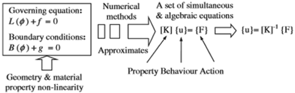
Casting simulations begin with modeling the physical phenomena through mathematical equations. In a mathematical perspective, models are expressed as governing equations and boundary conditions. Due to the non-linearity of models in terms of both geometry and material properties, numerical methods have to be used to avoid non-linearity and thus formulate simultaneous and algebraic equations. The set of developed equations is then used to explain casting process in the form of action–behavior–property relationship. 2 In a metal casting process, the actions is supplying a metal casting process, the action is supplying molten material to the mold, the behavior is the flow of molten metal within the mold, and the behavior is further decided by properties of the molten metal. The physical and mathematical modeling perspective of this relationship is presented in Figure 3.
Action–behavior–property relationship from physical and mathematical perspective in a casting process. 2
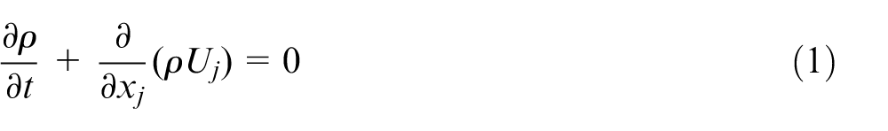
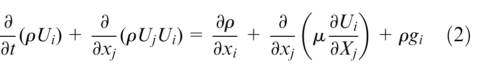
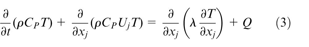
A relationship between an actual casting process, simulation procedure, modeling of physical phenomena, governing equations, and output variables is illustrated in Figure 4. Inputs required for a casting simulation are usually material properties and process parameters. Simulation results, however, demonstrate the physical behavior of the casting process and the final microstructure, defects, and properties of the cast products. From modeling point of view, three important phenomena in any casting process simulation are mold filling, solidification and cooling, and stress and strain profile of the cast parts. In each of these phenomena, a certain set of governing equations are employed. For example, mold filling is modeled by continuity equation, momentum equation (Navier–Stokes equation), and the energy equation. 30 Equations (1)–(3) represent the complete forms of continuity, momentum, and energy equations, respectively, and thus modified accordingly if the density is assumed to be constant and/or the molten metal is a Newtonian fluid.
Continuity equation
Momentum equation (Navier–Stokes equation)
Energy equation
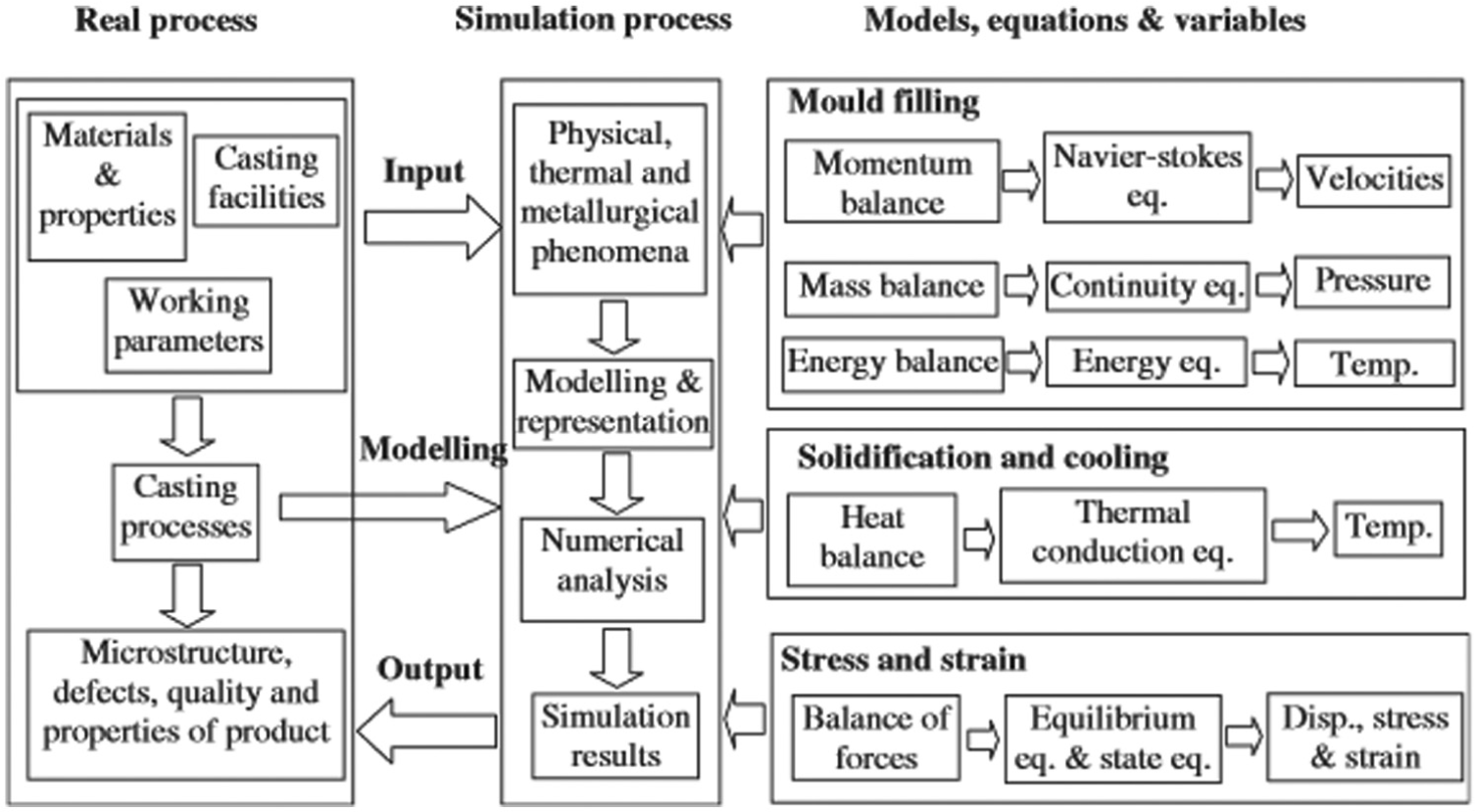
Relationship between the process, modeling, simulation, and output variable. 2
The non-linear nature of equations (1)–(3) requires a numerical method to obtain a set of simultaneous and algebraic equations, the solution of which determines the velocity, pressure, and temperature of the molten metal within the mold. The modeling of solidification properly calls for the solution of energy equation (and the continuity and momentum equations if fluid flow is not neglected). 31 The main objective of this modeling is to obtain temperature distribution in casting and to identify the solidification behavior. For stress–strain distribution in castings, equilibrium equations and Hooke’s law are generally used to provide the relationship and thus the magnitude of displacement, stress, and strain. 30
Casting process simulation
Casting simulation provides an in-depth understanding of the process and mechanisms of defect formation. A complete framework of metal casting process simulation is presented in Figure 5. The product geometry is extremely important in determining the casting system design and process parameters. Besides the mathematical modeling as explained in section “Mathematical modeling in a casting simulation software,” a 3D model of casting system is developed in any CAD software AutoCAD, CATIA, I-DEAS, Pro-Engineer, SolidWorks, SolidEdge, and UG-NX. This 3D model consists of part cavities together with sprue, gating and runner system, cores, and so on. While modeling a casting system, the physical models simplify the engineering problems that might occur during a real casting process, mathematical models determine the initial and boundary conditions and process constraints, and the numerical models decide upon the element types, meshing, and solution parameters (iteration specifications and convergence criteria).
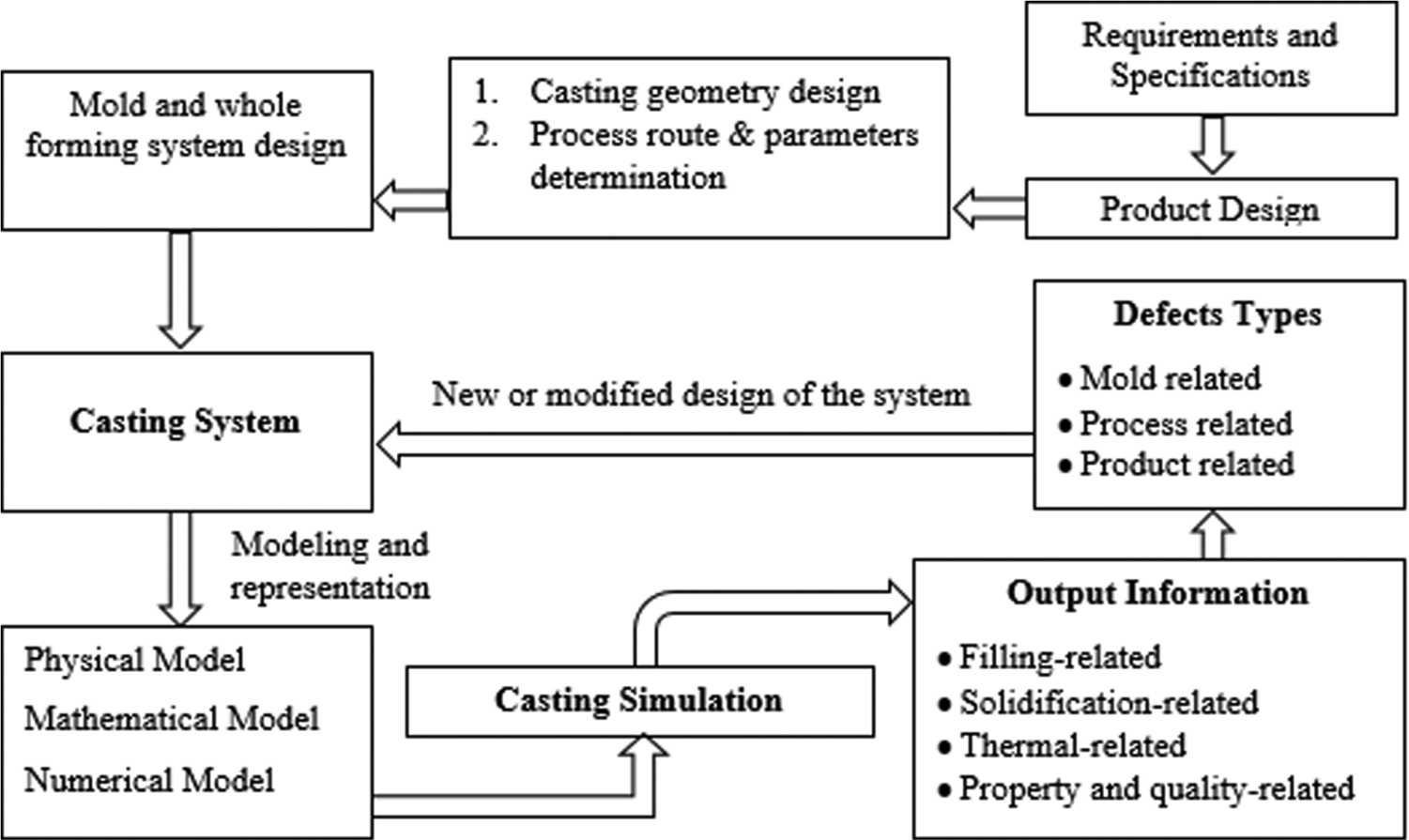
Casting simulation process for defects identification.
Simulation results provide information about filling of molten metal in the mold, solidification behavior, quality, and defects of the cast products. Generally, defects are attributed to improper mold design, irrational process parameters, and inappropriate product design and thus referred to as mold-related, process related, and product-related defects. Once the defects and the mechanism by which they are produced are identified, necessary modifications are done wherever required. The new casting system is then re-simulated until a casting is obtained which is either free from defects or contain defects within the permissible limits set by the designer.
Casting simulation results
Casting simulations result in three major aspects of a complete metal casting process: filling, solidification, and stress analysis. Each of these three simulation types reveal sources and causes of casting defects and thus provide an opportunity to rectify any errors prior to a physical casting process in foundry.
Filling process simulation
Mathematical modeling and simulation of conservation of mass, momentum, and energy in a filling process provides information about velocity of molten material within the mold cavity, the direction of flow, and temperature and pressure at various instances within the mold. Physical and thermal characteristics of the filling process are derived from these results, some of which are as follows:
Flow front progression, turbulence in flow, filling evenness;
Entrapment of air and gases within the mold so that proper venting can be designed;
Temperature profile within the mold;
Filling sequence and occurrences of over flowing;
Velocity profile of molten metal within the mold;
Odd behaviors such as splashing, misruns, cold shuts, and so on during filling.
All the above characteristics enable users to ensure a reasonable filling pattern that produces high-quality cast products. Filling process parameters may also be optimized based on the results of filling simulations.
Solidification process simulation
Solidification in casting process is generally complex, where physical, thermal, and metallurgical phenomena take place simultaneously. Solidification simulation provides information about how these phenomena are occurring in process conditions together with the defects that might arise during solidification phase. Some key findings of a solidification simulation include the following:
Cast area that solidifies last in a cast product;
Sequence of solidification and temperature profile within the mold;
Validation of cooling design;
Validation of runner design in a mold;
Defects due to shrinkage and microporosity and remedial actions to avoid such defects;
Appropriate riser geometry, size, and location within the mold.
Stress and strain simulations
The stress and strain simulation demonstrates the state of cast parts after ejecting from the mold. The results of these simulations may include the following:
Identification of dimensional inaccuracies in cast part;
Residual stress generation and distribution in cast part;
Defects arise due to stress and strain;
Temperature profile in ejected cast part;
Design improvements in casting design such as modifications in riser design to reduce stresses.
Case studies using casting simulation tools
Efforts have been made in the past to obtain high-quality defect-free castings by developing an in-depth understanding of the areas such as (a) design of runner and gating systems,32–40 (b) design of feeding systems (locations and number of risers),41–45 (c) filling and solidification during different casting processes,46–50 (d) casting process parameters (thermo-physical data, injection parameters, etc.),50–54 (e) stress distribution in cast products,55–59 and (f) quality control and assurance of the cast products.60–62 Some of the case studies in these areas are discussed in forthcoming sections.
Simulation-based gating, runner, and feeding system design
Mi et al. 50 simulated the filling and solidification stages of a valve block. The results obtained were filling and solidification sequences, thermal stress distribution, and prediction of possible defects, for example, shrinkage and cold shuts. Casting design was modified in three aspects, specifically, feeding system, gating system, and the mold. Figure 6 shows the original and modified casting designs for the valve block. The geometry of risers was changed from rounded rectangle to cylindrical due to the capability of the later to supply more liquid metal during solidification. Cooling capacities of hotspots were increased by introducing chills at appropriate positions within the mold. Modified casting design replaced the two ingates configuration by a single gating system as shown in Figure 6. With new configurations, the defects such as misruns and cold shuts are avoided. Chills helped in solidification of the casting from bottom and any deficiency due to shrinkage was overcome by the risers containing ample amount of molten metal. It was reported that modified process scheme eliminated the cracks on the surface of valve body.
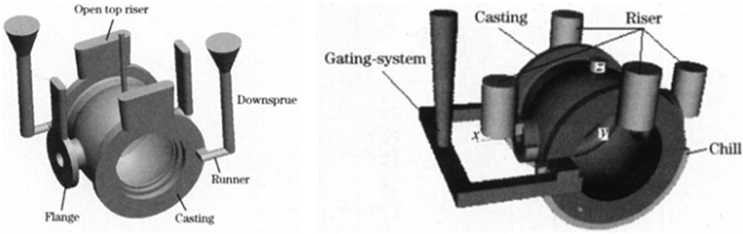
Casting design for a valve body (left: original and right: modified). 50
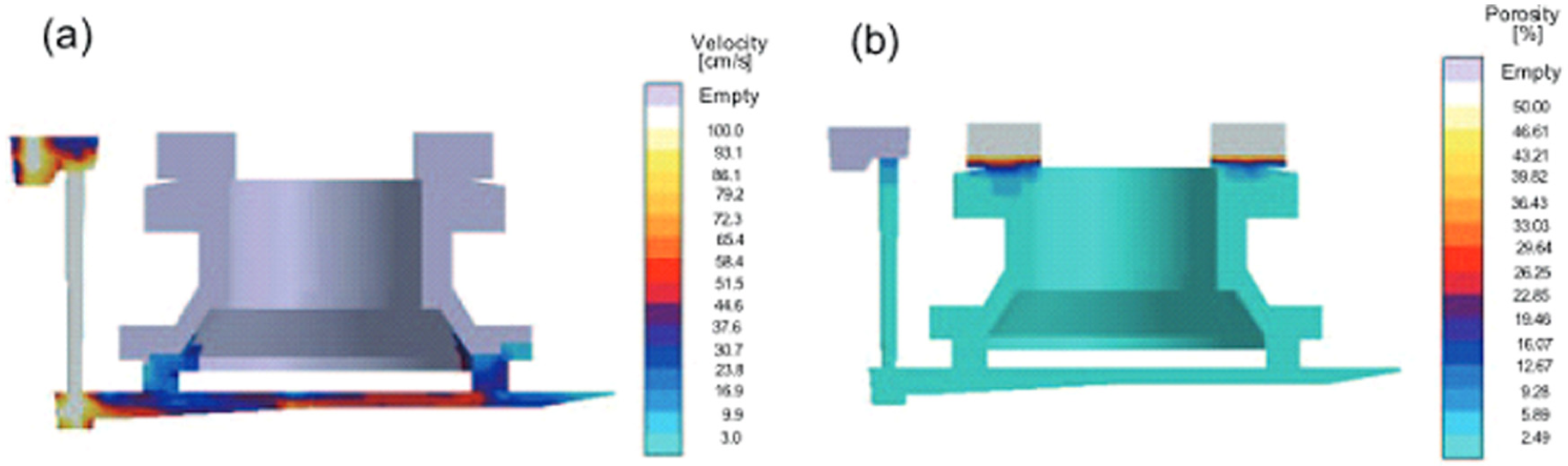
The design and optimization of gating and runner system for die casting of thin-walled components was studied by Hu et al. 32 Two different runner and gating designs were numerically studied using a commercial CAE package MAGMASoft. Side gating position was selected because the cast part was very thin, and side gate offers the shortest flow distance. The runner system was designed with a tapered geometry for a homogeneous filling. However, the simulation indicated the swirling flow within the cavity which caused the last filled area to locate within the inner portion of the cast part. A new runner and gating system was designed where the split gating system of the preliminary design was replaced by a continuous gating system. Figure 7 shows the preliminary and modified gating and runner design configurations together with the last filled areas. The new optimized design increased gate area and slightly reduced gating speed to provide homogeneous mold filling and to locate the last filled areas at the upper edge of the part.
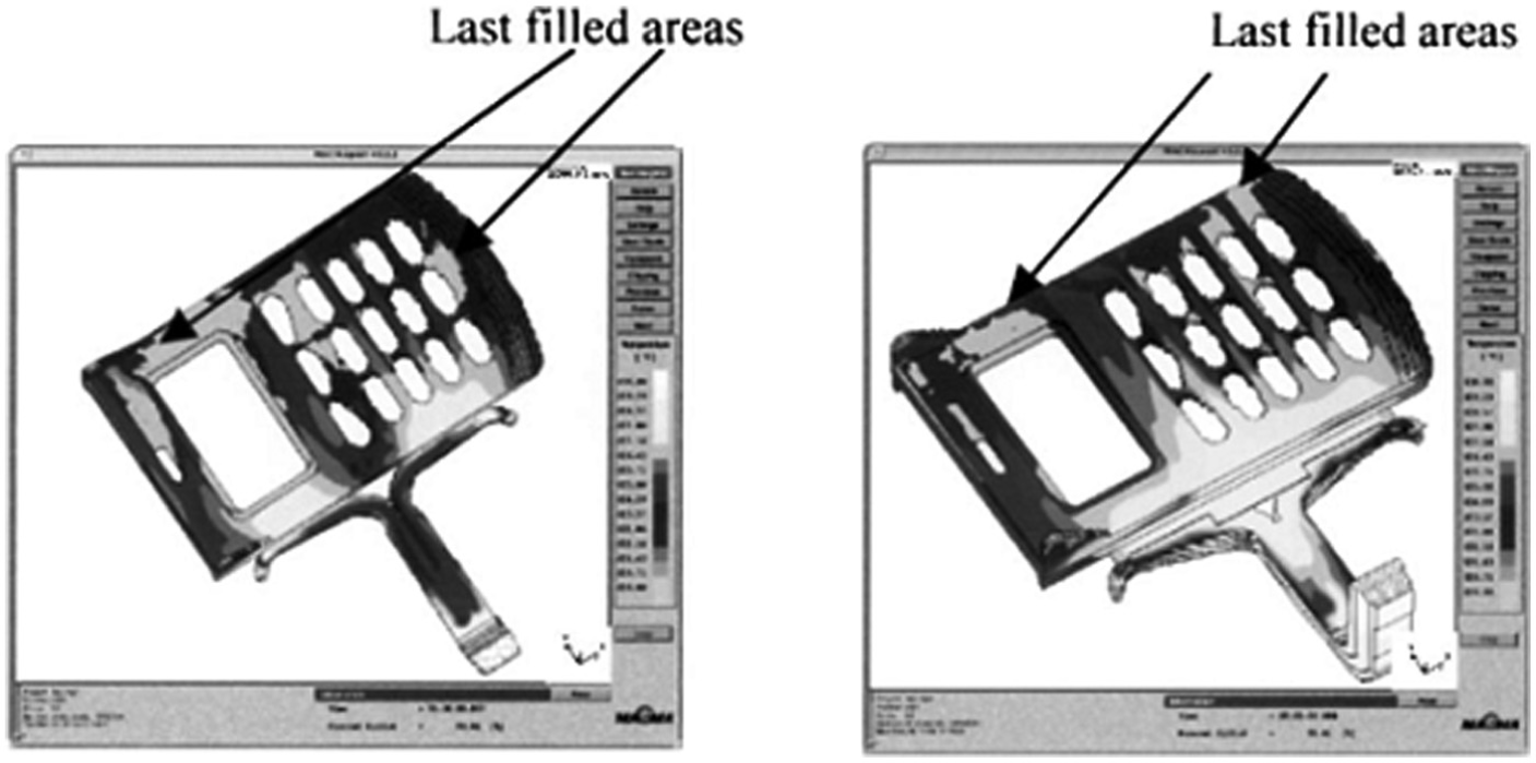
Gating and runner design (left: preliminary and right: optimized) for thin-walled cast part. 32
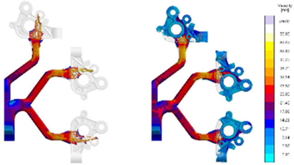
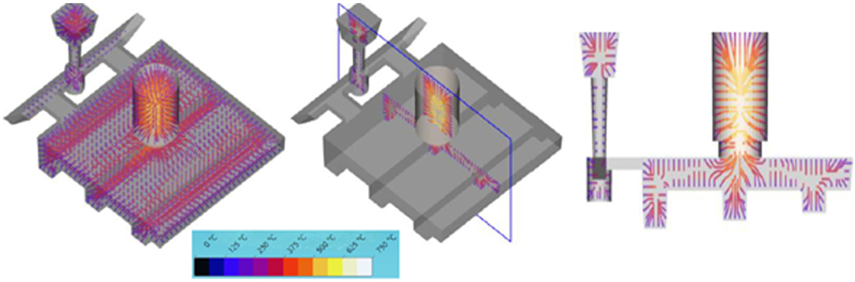
Multiple objective optimization method was used by Sun et al. 34 for a cylindrical magnesium alloy casting. The gating system was optimized by changing four parameters: ingate height, ingate width, runner height, and runner width. Bottom filling approach of the mold was applied as shown in Figure 8. Filling velocity, shrinkage porosity, and yield were set as main criteria to evaluate casting quality. Simulation results for filling velocity and shrinkage porosity are presented in Figure 9. In total, three levels of gating system parameters and nine experiments were performed, where it was confirmed that runner with small height and large width is effective in reducing the metal velocity at the ingate which is consistent as reported by Hu et al. 32 and Mi et al. 50
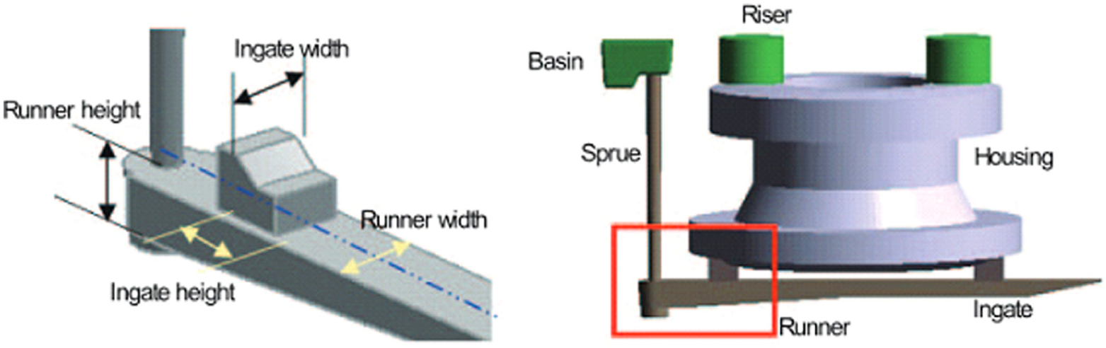
Gating system design and gating parameters for cylindrical magnesium casting. 34
Simulation results for (a) filling velocity and (b) shrinkage porosity prediction in cylindrical magnesium casting. 34
In another work by Kermanpur et al., 48 filling and solidification in a multi-cavity casting mold are simulated using Flow 3D. Two automotive components, brake disc and flywheel, had to be cast in large amounts with grey iron using multi-cavity molds. With Flow 3D, the turbulent flow of the melt was modeled by two equation k-ε turbulence model and flow through porous ceramic filter in the gating system was modeled by the well-known Darcy’s law. The filling and solidification sequence for two mold design configurations, that is, three- and four-cavity molds were presented as shown in Figures 10 and 11, respectively. For brevity, only final results of filling and solidification sequences in the two configurations are included and the rest of results are available in Kermanpur et al. 48 It was suggested to modify the geometry of gating system to avoid porosity which can be introduced due to partial filling of first gate until the mold is half filled. The non-uniformity in the solidification behavior of a three-cavity mold configuration suggested that a symmetrical configuration as in the case of four-cavity mold provides uniform filling of cavities in a mold. In terms of defects, the simulation predicted the location of hotspot in brake disc component which was reflected by micro-shrinkage in the physical experiments. It was recommended to decrease the superheat temperature to reduce the possibilities of any such occurrence in the cast parts.
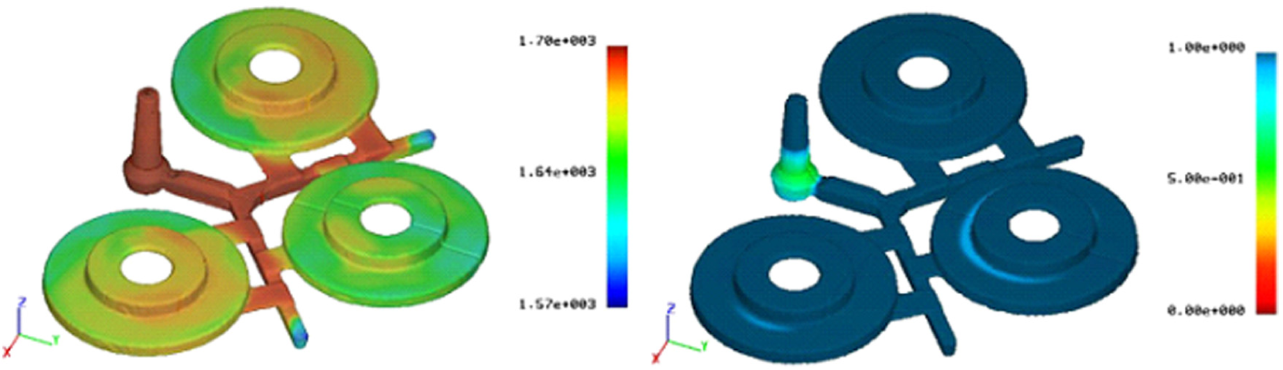
Final results of filling (left) and solidification (right) sequences for the brake disc in a three-cavity mold. 48
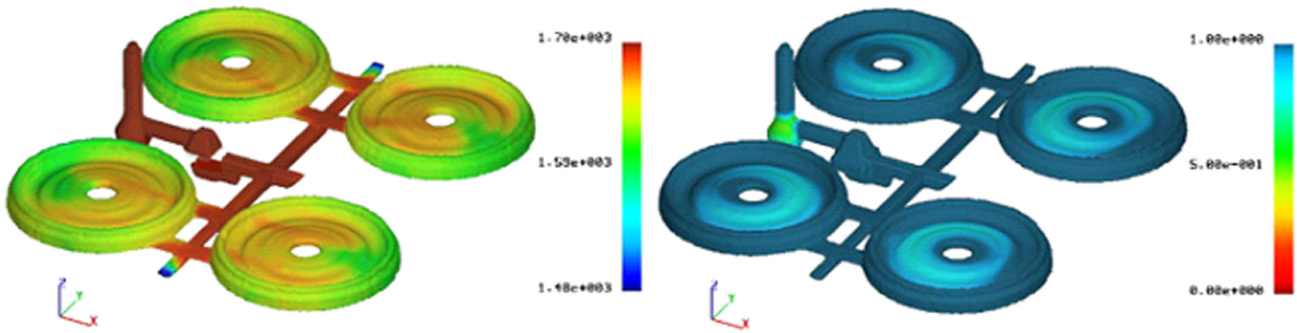
Final results of filling (left) and solidification (right) sequences for the flywheel in a four-cavity mold. 48
Systematic and autonomous optimization via simulation
In more recent years, the systematic and autonomous optimization of casting has been introduced in casting simulation tools.35,37,38 Autonomous optimization refers to the use of a simulation tool as test field or virtual experimentation. Systematic and autonomous optimization provides improved casting quality, productivity, material consumption, and so on, for which different manufacturing parameters such as casting process conditions, materials, process timings, and so on, or geometries (i.e. gating system, riser design, location and size of risers and/or chills) can be altered in computational experiments. Figure 12 represents a schematic sequence of design optimization with MAGMASOFT studied by Sikorski et al. 38 A simple casting layout was optimized for its gating system as shown in Figure 13(a), which was used to produce aluminum parts under gravity casting. Initially, a symmetric layout was used to feed the cavities through main runner. However, this configuration resulted in the defects in 20%–30% of the parts as shown in Figure 13(b). Hence, the main aim of the study was to eliminate these defects by optimizing the runner design but keeping the same overall pattern layout.
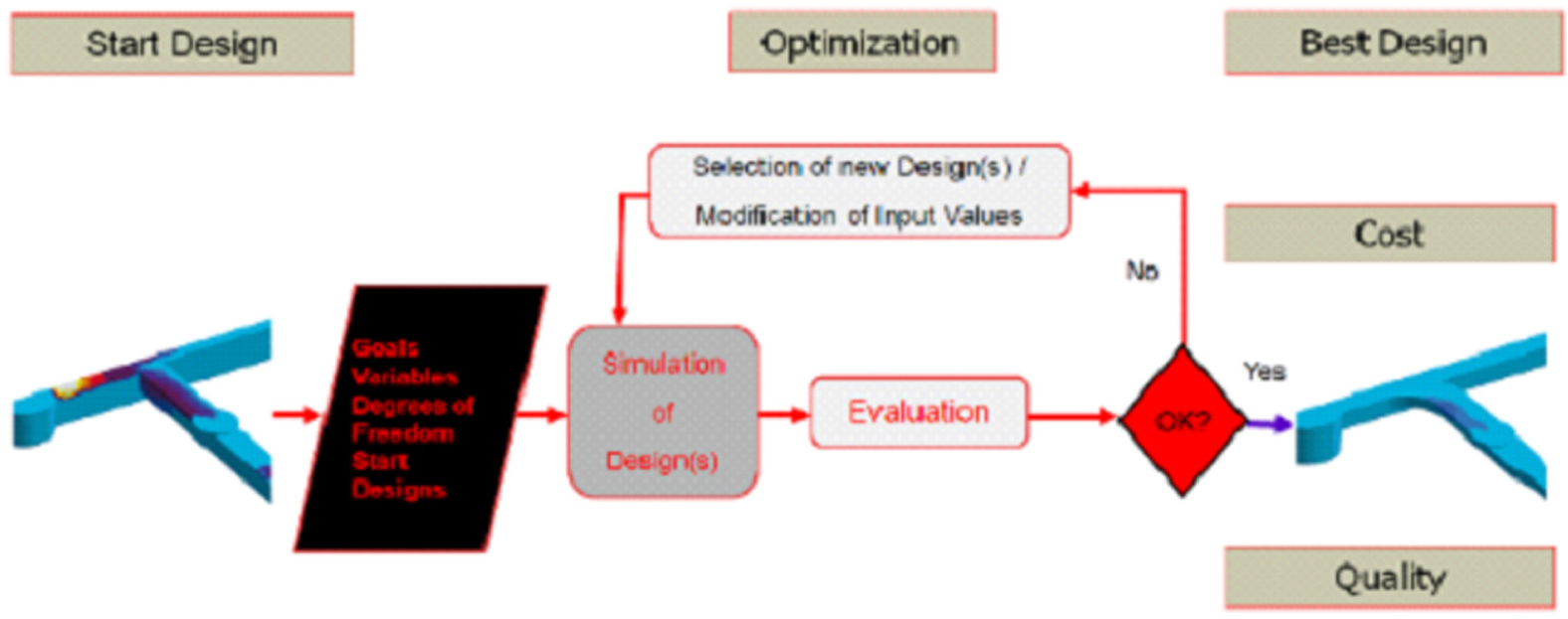
Schematic sequence of a design optimization with MAGMASOFT. 38
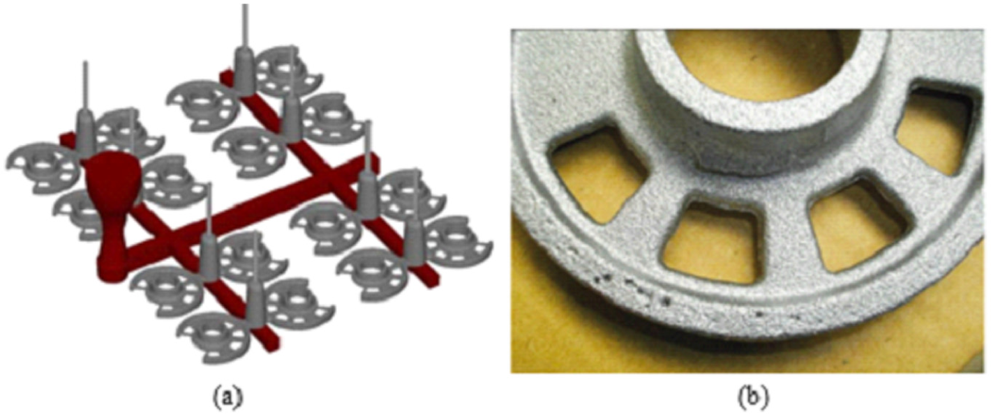
(a) Initial situation of casting model layout and (b) oxide defects in initial casting. 38
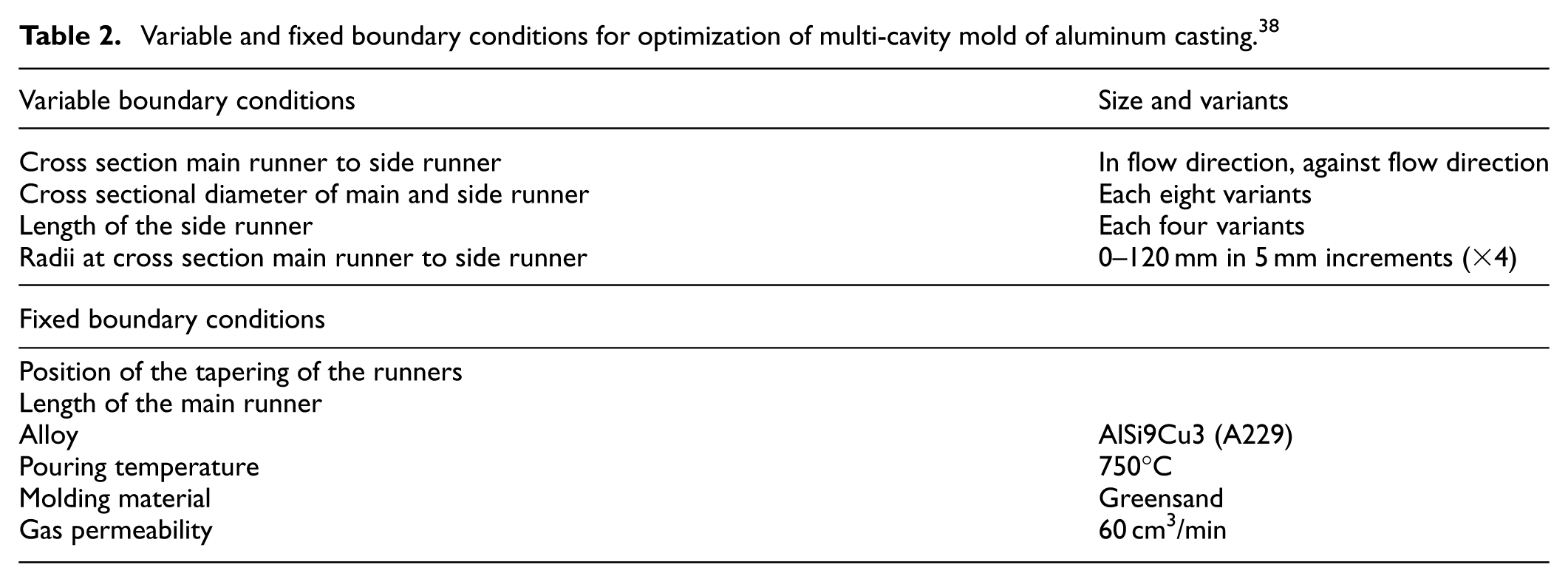
The optimization goal set in the study was reduction in the filling time difference between the cavities and minimization of entrapped air throughout all cavities. Figure 14 shows the comparison of filling time results between two different runner designs, and Figure 15 compares the flow conditions between two different gating designs where all light-colored areas show various levels of air entrapment inside the gating systems. The variable and fixed boundary conditions for optimization are presented in Table 2. The filling time and air pressure for the optimized final design variants are presented in Figure 16(a) and (b), respectively. The filling time difference was found to be 1.5 s in Figure 16(a), whereas the air pressure results in Figure 16(b) are showing minimum values in the casting. Figure 17 depicts the initial situation and final optimized solution using the filling time difference criterion. In Figure 17(a), the filling time difference was observed to be 4 s which was reduced to less than 1.5 s in Figure 17(b). The real casting after the autonomous optimization is found to be free from casting defects especially due to oxides.
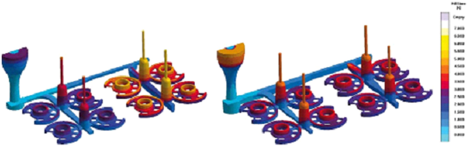
Results of filling time for two different runner designs. 38
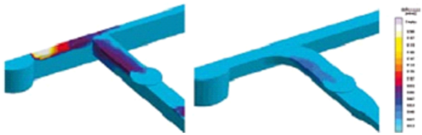
Comparison of flow conditions between different gating designs. 38
Variable and fixed boundary conditions for optimization of multi-cavity mold of aluminum casting. 38
(a) Filling time and (b) air pressure for the optimized final design variants. 38
(a) Initial situation and (b) final optimized solution using the filling time difference criterion. 38
Hahn and Sturm 35 presented the comparison of design of experiments (DOE) and virtual autonomous optimization for selected industrial examples. The study reported a steel casting example as shown in Figure 18 where the number, location, and dimensioning of feeders and chills were investigated with respect to their impact on shrinkage distribution in the casting. The results obtained from DOE were compared against autonomous optimization and it was found that the autonomous optimization led to a further reduction in shrinkage severity by fine tuning the chill size. Figure 19 shows the shrinkage distribution in castings with two feeder designs.
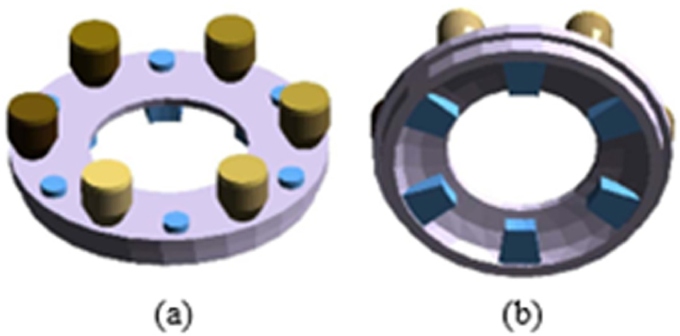
Ring-shaped steel casting with feeders and chills in (a) cope and (b) drag. 35
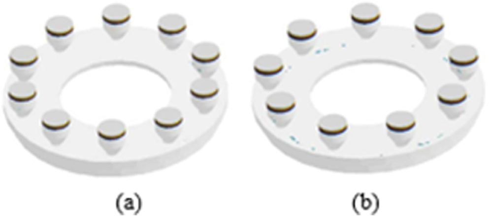
Shrinkage distribution in castings with two feeder designs: (a) best design from autonomous optimization and (b) closest design from DOE. 35
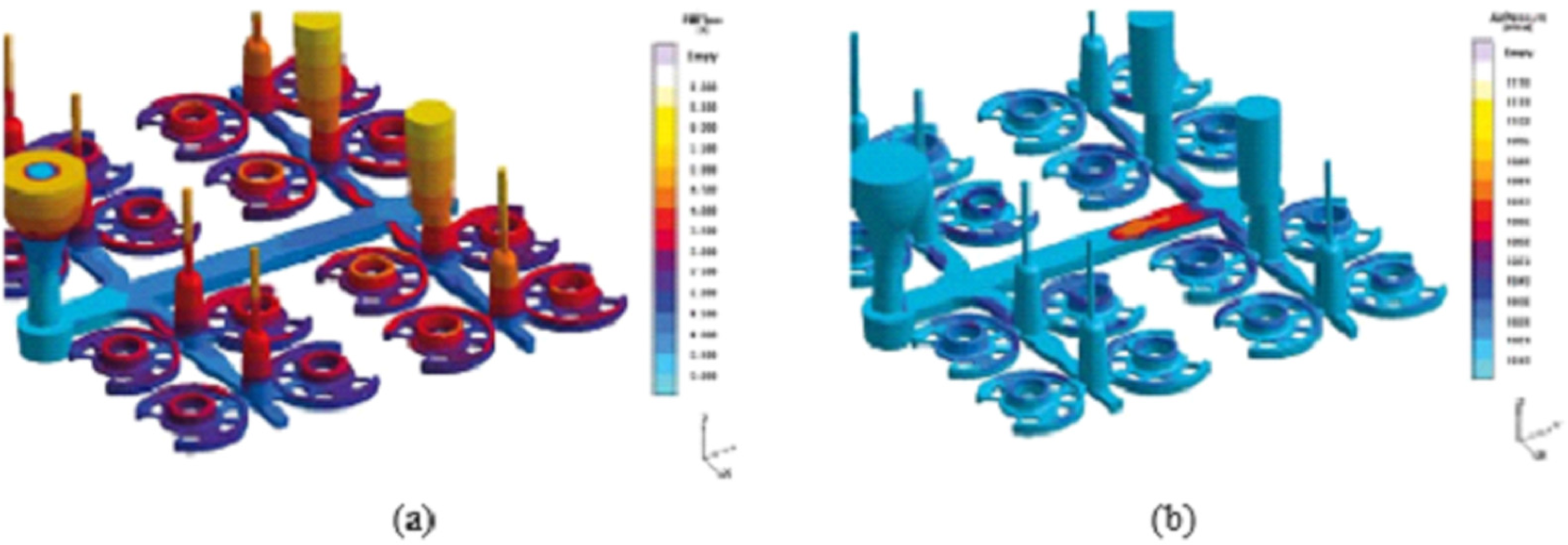
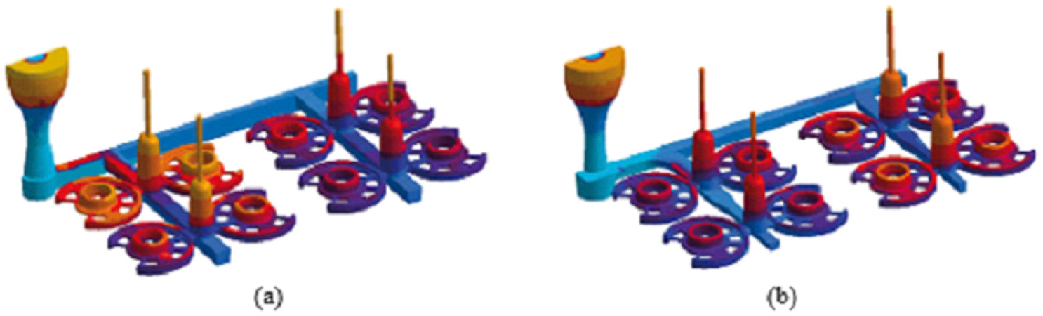
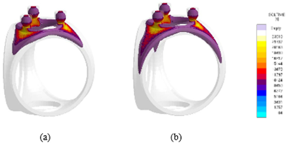
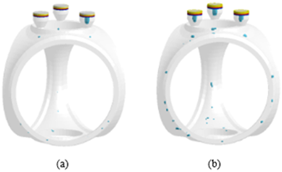
Another example of method optimization of a ductile iron wind turbine hub was discussed by Hahn and Sturm. 35 Three risers were placed directly on the top of casting, where highest mass accumulation was expected. The circular flanges where rotor blades connect were provided with cooling chills as shown in Figure 20 so that the directional cooling can be achieved. Three different configurations were studied using different feeder sizes and chill patterns. From autonomous optimization, a very good quality casting was expected with 30 chills, as shown in Figure 21(a). Figure 21(b) provides the result if minimum number of chills, that is, less than 10 were used in the design. Shrinkage porosities also reduced in layout with more chills as shown in Figure 22(a) as compared to the one with less chills as shown in Figure 22(b).
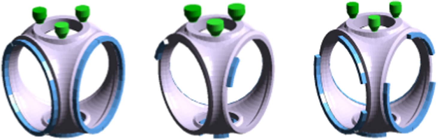
Three configurations with differing feeder sizes and chill patterns for ductile iron wind turbine hub. 35
Distribution of solidification time for different layouts: (a) 30 chills and (b) <10 chills. 35
Distribution of shrinkage for different layouts: (a) 30 chills and (b) <10 chills. 35
Hahn and Sturm 35 also simulated multi-cavity molds by taking an example where six parts had to be cast simultaneously as shown in Figure 23(a). Different runner designs are also shown in Figure 23(b). It was aimed to reduce the difference in time filling for all cavities using different runner configurations. Figure 24 represents the filling of the die cavity using an appropriate runner system at two different times. The cavities were filled homogeneously. However, a detailed analysis of oxidation failed to produce satisfactory results as can be seen in Figure 25.
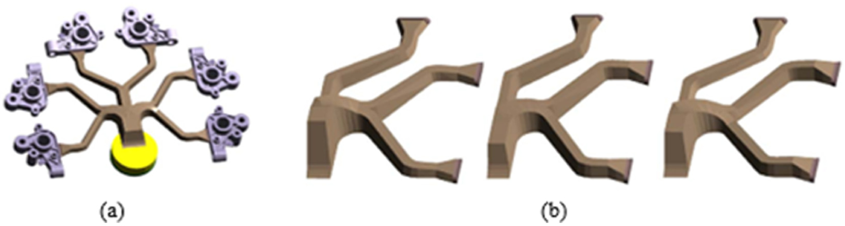
(a) Casting layout for a high pressure die casting process with six cavities and (b) three different variants of the runner system. 35
Distribution of flow velocities at two points of time. 35
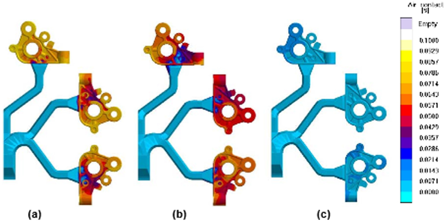
Analysis of air contact (a) before the optimization, (b) after geometrical optimization of the runner design, and (c) additional improvements in oxide entrapment. 35
Feeder design optimization with auxiliary products
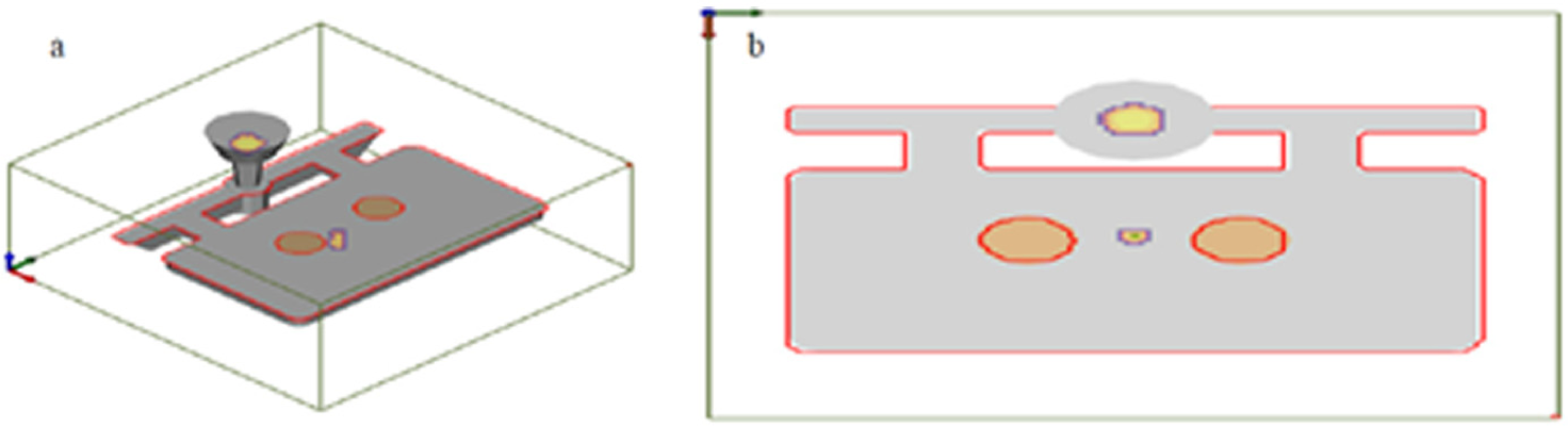
In one study, Choudhari et al. 43 demonstrated the shrinkage defect elimination in stepped plate casting using AutoCAST-X software followed by experimental validation. This software uses gradient vector method to calculate the temperature gradients (feed metal paths) inside the casting. From this, locations of shrinkage defect are identified. This is relatively a new method and is much faster than traditional FEM-based ones. Solidification simulation was carried out to identify shrinkage-related defects. Based on the results of the simulation, the feeder was placed directly above the hotspot. Solidification analysis was again carried out to analyze the effect of using feeders and the results are shown in Figure 26.
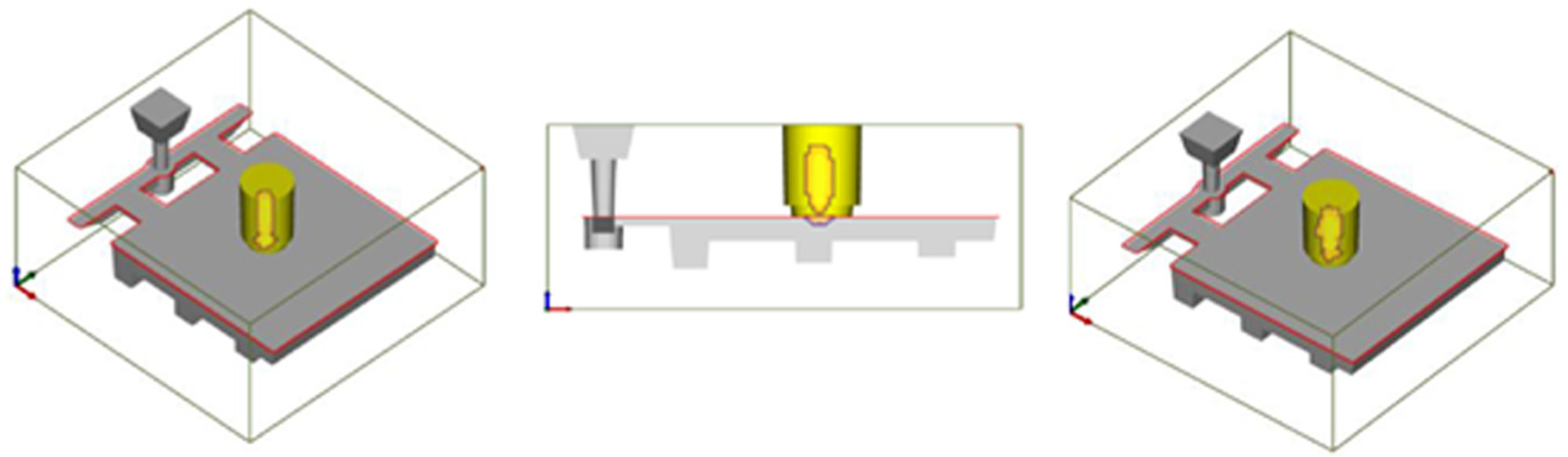
Partial shifted position of hotspot in the feeder for stepped plate casting. 43
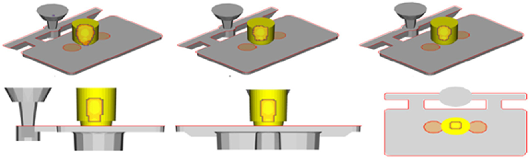
It was found that the hotspot did not completely move into the feeder. An exothermic sleeve was then attached to the feeder which would delay the solidification of the metal inside it. The simulation results with an exothermic sleeve attached to the feeder are shown in Figure 27. The hotspot shifted completely inside the feeder, thus eliminating the shrinkage defect problem. The feed metal paths indicating the directional solidification are shown in Figure 28. The regions where long and hot feed paths converge are the ones that are most susceptible to shrinkage defects. It is evident from Figure 28 that all the long and hot feed paths are ending inside the feeder. Three criteria were used to evaluate the feeding design, that is, quality, feeding yield, and feeding efficiency. The simulation results were then experimentally validated and it was found that the cast product was free from shrinkage defects.
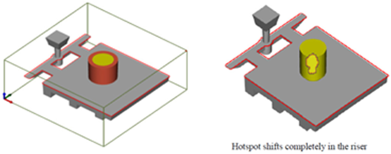
Effect of exothermic sleeve on the position of hotspot in stepped plate casting. 43
Feed metal paths (3D as well as in cross section) for stepped plate casting. 43
In another study, Choudhari et al. 44 optimized the feeder location for a cast cover plate to eliminate the shrinkage defect. The geometric design of the cover plate was also modified by providing sufficient draft and radius at the critical junction to allow the molten metal to completely fill the mold. To eliminate the shrinkage defect, the optimum location of the feeder was determined using the AutoCAST-X software. Solidification simulations were carried out to predict the location of the hotspot. The results are presented in Figures 29 and 30. The hotspot was found to be in the middle of the cylinders and the feeder was placed at that location. The solidification simulation was carried out again and the results indicated that the hotspot shifted inside the feeder. The feed metal paths for the cast product are shown in Figure 31. The hot and long feed paths are the most critical and it can be seen that all of them are ending inside the feeder. Both the shrinkage macroporosity and the microporosity were found to be 4.47 cm3. A wooden pattern with modified geometric features and feeder location was prepared. Molten aluminum was sand cast and it was found that the cast cover plate was free from both of the defects that it had previously, that is, shrinkage cavity and incomplete filling.
(a) Hotspot indicating the last solidifying region and (b) probable location of the feeder indicated by the software. 44
Shifted position of hotspot with the application of feeder during solidification. 44
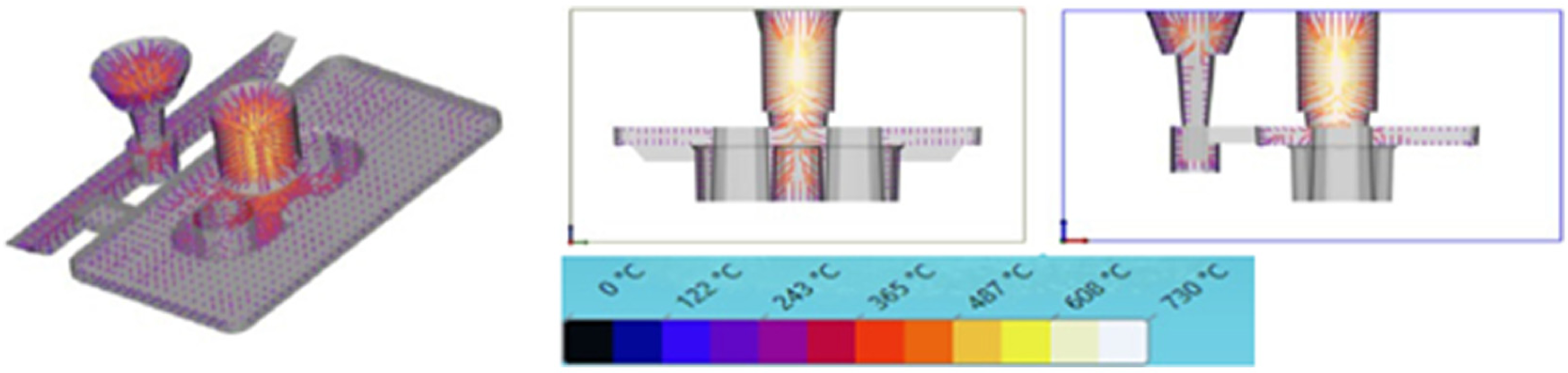
Feed metal paths in 3D and in cross section for a cast cover plate. 44
Stress and strain simulations
Egner-Walter and Kothen 57 reviewed the application of a numerical simulation to stress-related problems in casting industry. The study first explained the formation of residual stresses and distortion in castings. Solidification and cooling to room temperature in casting process occurs with an inherent inhomogeneous temperature distribution resulting in residual stresses as shown in Figure 32. The thinner areas within the lattice cool faster and thus thermally contract which produces tensile stresses. However, at high temperatures, thermal stresses are relieved due to lower yield stresses. The highest stress and plastic deformation occur when the temperature difference between faster and slower cooling rate areas is maximum. Upon complete cooling to room temperature, compressive stresses arise in thin areas, whereas tensile stresses arise in the thick central area as shown in Figure 32. In order to simulate the distortion of a structural component, a die cast rear door lock panel for a passenger car was selected. It was observed that tensile stresses are observed in whole component as shown in Figure 33(a). Figure 33(b) represents the temperature field at ejection and it forms the basis for the formation of stresses and deformation during solidification and cooling to room temperature. The runner being hotter contracted more in the subsequent cooling phase and pulled the casting inwards toward it as shown in Figure 34. The swan neck moved in an upward direction, as the upper side of the casting, which faced the shot slug, had a higher temperature than the lower side after ejection.
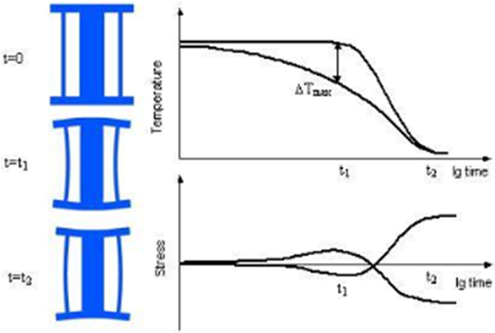
Formation of residual stresses and distortion in a stress lattice. 57
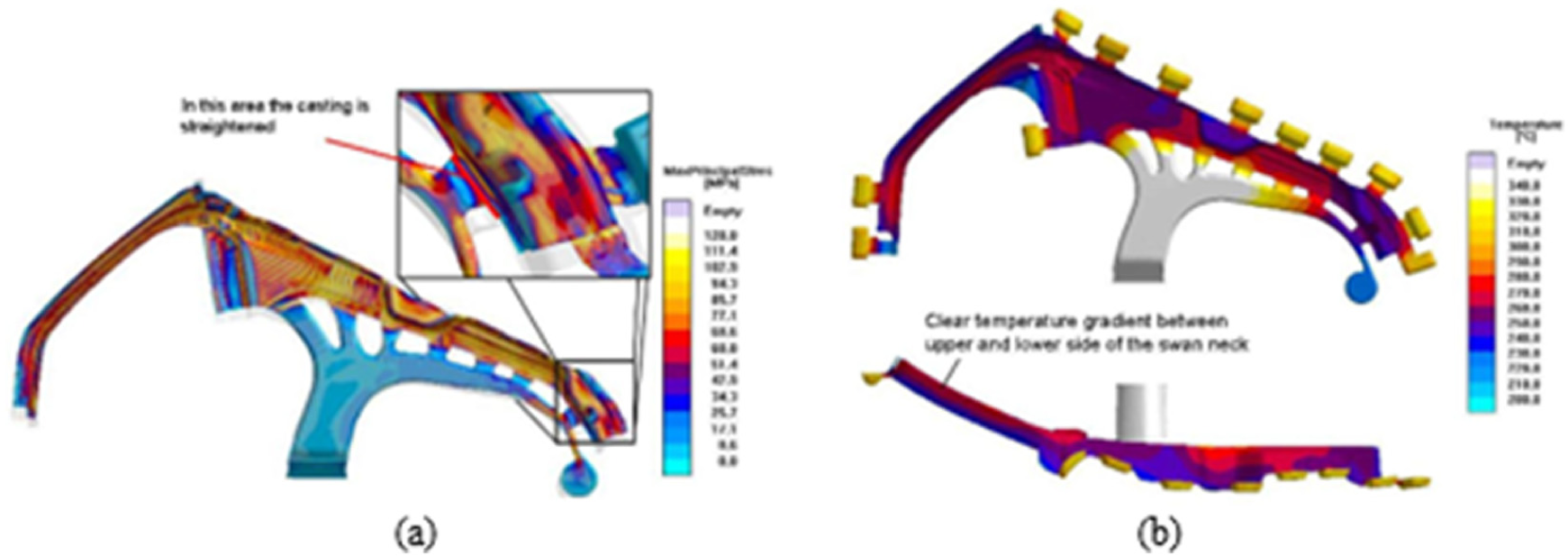
(a) Maximum principle stress in the rear door lock panel casting just before ejection and (b) temperature distribution in casting and runner at ejection. 57
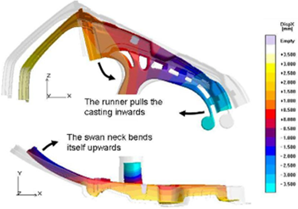
Deformation of the casting after cooling to room temperature: original geometry (semitransparent grey) and deformed geometry. 57
Hot tears are the tensile cracks that occur during solidification and are challenging to designer especially in high pressure die castings. This effect was studied by simulating the hot tear criteria for a flywheel as shown in Figure 35. It was suggested that hot tears can be avoided by modifying process parameters and cooling conditions, or by minor changes in the geometry of casting. The distortion during heat treatment of a cast bulk head was also simulated to see the effect on residual stress levels. Annealing of a bulk head casting was selected as an example, where only half of the model is simulated due to symmetry. Figure 36 depicts the stresses and deformation after solution annealing where the maximum stresses were 0.9 MPa which are much smaller than 20–50 MPa in as cast product. Distortion occurred during annealing was also shown with the maximum displacement of around 4.6 mm.
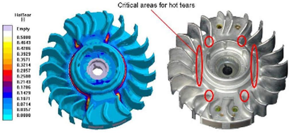
Prediction of hot tears in a flywheel casting using hot tear criterion. 57
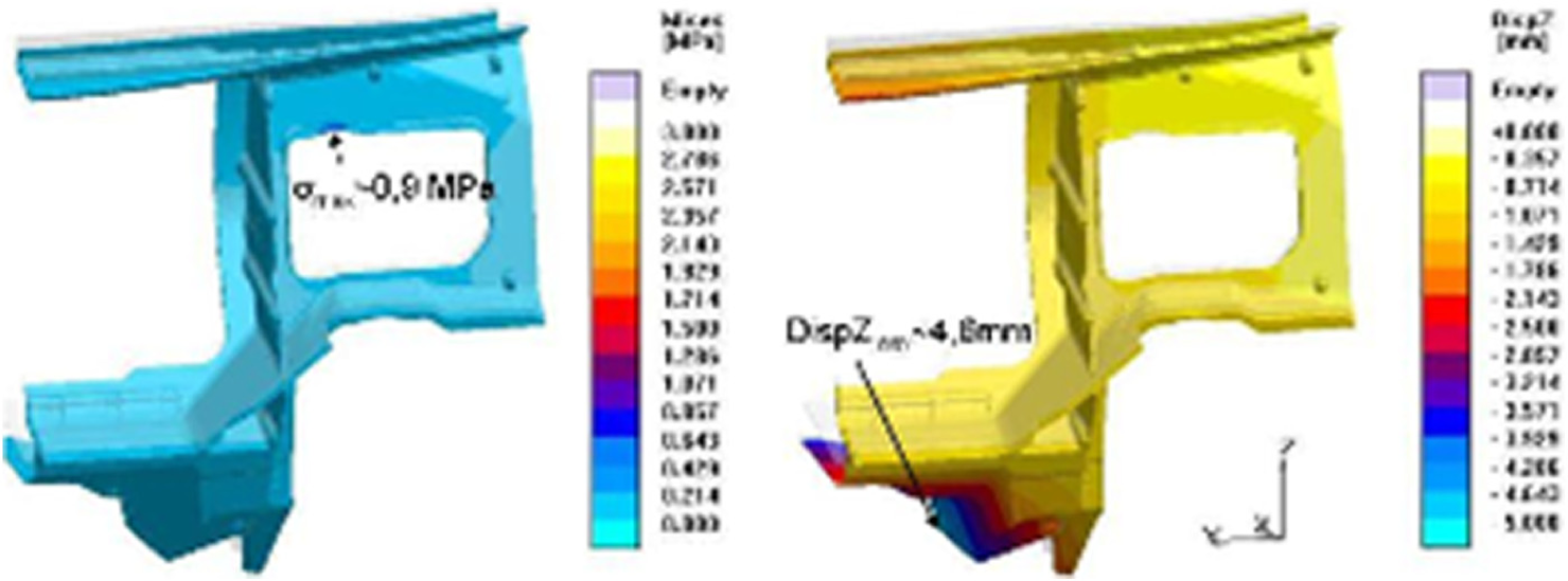
Stresses and deformation of the bulk head after solution heat treatment. 57
The case studies presented above provide details on how casting simulation tools are increasingly being utilized in modern foundries. Initial numerical simulations help in identifying the defects, many of which can be directly attributed to inappropriate casting design and process parameters. Therefore, simulations of physical casting experiments assist in design and process optimization resulting in good quality and defect-free cast products. The commercially available simulation programs can be modified for a particular casting process, such as investment casting,47,63 to predict the flow conditions of the melt, filling sequence, and defect formation for different geometries and process variables. The studies by Sikorski et al. 38 and Kermanpur et al. 48 highlight the use of multi-cavity molds where the problem arises due to non-uniform filling of the cavities within the mold. Although this problem can be eliminated using a symmetric layout of cavities in a multi-cavity mold with appropriate gating and runner design, there is a need to develop a model that can track the inclusions during mold filling. 48 The studies revealed that often casting defects are mainly due to inappropriate design of gating system, runners, and risers, and so on.32,34,38,39 DOE is a promising method for deciding upon processing parameters to reduce the rejection due to defects in castings;36,52 however, for simultaneous improvement in casting yield and defect minimization, process simulations are considered to be the most efficient method in the shortest possible time.
Integration of casting simulations with mechanical performance simulations
In more recent years, casting simulations are combined with mechanical performance simulations to investigate the life of cast products in service.64–66 The effect of casting quality on service life is analyzed by taking the predictions of defects such as shrinkage and porosity from casting simulation results and transfer them to stress and fatigue life simulations. Hardin and Beckermann65,66 measured the porosity distribution through industrial radiographs in cast steel specimen and transferred the results to an elasto-plastic finite element stress analysis model. The porous metal plasticity material model in the FEA software ABAQUS was used to investigate the effect of porosity on plasticity and ductile failure. Measured and predicted stress–strain curves and fracture behavior were found to be in good agreement. It was reported that ductility of casting is significantly compromised due to porosity as already well predicted by the model. The study advances the ability to produce more reliable and high-quality cast products by integrating casting process modeling and simulation, with stress and fatigue analysis of castings to predict the life of the cast part in service, during the design of the part produced in an optimized mold before actually manufacturing and testing it.
Conclusion
The key concluding observations and recommendations from this exploratory study are as follows:
Literature review revealed that it is challenging to precisely model the boundary conditions and to validate the simulation results with the physical experiments.
Casting simulations are capable of examining the effects of several casting parameters such as melt temperature, pouring time (velocity), gating and runner system design, riser design, mold configuration (single cavity or multi-cavity) in producing sound castings.
Most cast products are obtained with residual stresses. The accurate prediction of these residual stresses at design stage can greatly help in providing appropriate heat treatment strategies to reduce casting failures in service.
Autonomous optimization method in casting simulation softwares must be fully utilized at its best to obtain good quality and defect-free castings.
A thorough comparative study of simulation softwares is needed which explores all the opportunities in terms of time required for processing information, database of material properties, cost of the software, and accuracy of the results.
There are recent attempts in the literature to import the casting simulation results in FEM software to study the life of the part in service. This will determine the reliability of parts in actual services where the part is being used in dynamic loading of varying thermal and mechanical load cycles. This is a very promising direction and more rigorous work is needed in this area. The results should provide additional capabilities by integrating the reliability prediction modules in these softwares.
Footnotes
Appendix 1
Acknowledgements
This work is part of ME-701 Directed Research and ME-711 PhD Pre-dissertation courses at King Fahd University of Petroleum and Minerals (KFUPM) taken under the supervision of Professor Anwar Khalil Sheikh. The authors greatly acknowledge the support provided by KFUPM in this research.
Declaration of Conflicting Interests
The author(s) declared no potential conflicts of interest with respect to the research, authorship, and/or publication of this article.
Funding
The author(s) received no financial support for the research, authorship, and/or publication of this article.