
Abstract
Machining by parallel planes is a widely used strategy for end-milling of free-form surfaces on 3-axis numerically controlled machines. In industry, this type of machining is generally performed with a hemispherical tool. However, numerous studies have shown the benefits of torus-end mills over ball-end or flat-end mills. More than anything, the machining direction has much influence on productivity while using a torus-end mill. In this context, the choice of the machining direction is of paramount importance when using a torus-end mill in the machining of free-form surfaces. This paper presents an optimization of part machining direction allowing the machining time to be minimized while respecting the maximum imposed scallop height. This optimization methodology is then applied to an industrial part and measurements are performed on this part. The study highlights the interest of optimizing the machining direction and the benefits that can be drawn with respect to machining using a non-optimized direction.
Keywords
Introduction
Machining by parallel planes 1 is a common strategy for the machining of free-form surfaces on 3-axis numerically controlled (NC) machine tools, especially for the production of molds and dies. It is widely used in industry because it is reliable and robust, well-proven through years of practice. Indeed, this strategy allows on one hand to leave no uncut areas of the part, and on the other hand to ensure that the generated tool paths do not intersect (which is significant in terms of productivity).
When finishing free-form surfaces, the main criterion for assessing the quality of the machining is the scallop height, denoted
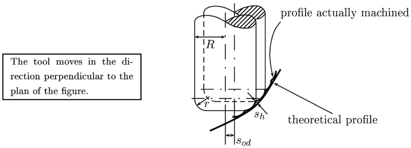
Scallop height.
In industry, the machining strategy by parallel planes is usually implemented using a ball-end mill. However, numerous studies have demonstrated the opportunity of using a torus-end mill rather than a hemispherical or flat-end mill.2–6 Indeed, similarly to the flat-end tool, the torus-end mill allows under certain conditions, for a given step-over distance, to obtain a lower scallop height than that allowed by the ball-end one. For a given scallop height (i.e. at constant quality), it then saves a lot of productivity. In addition, the torus-end mill avoids unsightly marks left on the part by the flat-end tool and preserves the surface integrity. 7 By combining the benefits of both of flat-end and ball-end tools, the torus-end mill appears to be the ideal compromise for finishing operations by end-milling of free-form surfaces.
The relationship between machining direction, step-over distance and tool geometry is well known. 8 Figure 2 illustrates this relationship for both ball-end and torus-end mills. This clearly highlights the fact that the torus-end tool is far more efficient when machining in the direction of greatest slope, while it is less efficient when machining in a direction perpendicular to the direction of highest slope.
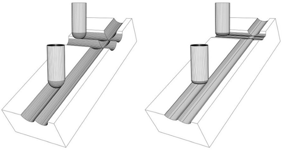
Relationship between machining direction and step-over distance using a ball-end mill (left) and a torus-end mill (right).
But while the maximum slope direction is quite obvious for a plane, like in Figure 2, in the case of a free-form surface, this direction is different for each point. Thus, the best direction for the whole surface cannot be determined easily.
In Quinsat and Sabourin 9 , the authors show that, even in the case of a ball-end mill, the machining direction is one of the most influential parameters on the machining time. In this case, the tool’s effective radius (see Subsection Context of this study for a comprehensive definition of “effective radius”) is invariant and only the angle between the direction of maximum slope and machining direction is influential. In the case of torus-end mill use, this parameter is even more influential since the effective radius of the toric profile that leaves traces in the material varies with the working direction. For a torus-end mill of major radius R and torus radius r, effective radius varies between r and infinity.
These considerations show that efficiency of a torus-end mill is highly affected by the machining direction. Thus, this direction has to be carefully chosen to be relevant for the whole surface machining.
For 3-axis machining, the milling direction is defined by position and orientation of the workpiece. Indeed, the issue of position and orientation of the workpiece is often considered in terms of dynamic behavior of the machine,10–12 or from the viewpoint of the visibility of surface to be machined.13,14 Few studies address the issue of the optimal machining direction. Among them may be mentioned, Quinsat and Sabourin 9 which is confined to the use of a ball-end tool. But these approaches are all based on local parameters and do not consider the surface as a whole. Therefore they are limited to providing the optimum machining direction at a point of the surface or calculating a first optimal path.15,16 If they are, for most of them, relevant and meaningful, their extension to the whole surface is not the result of a real optimization process.
Other authors consider optimization of free-form surface machining processes from other points of view than productivity. For example, in Balic and Korosec 17 the authors seek to optimize the quality of the surface using neural networks. Others seek to optimize the machining quality by adjusting the feed-rate of the tool.18–20
In the context of machining free-form surfaces with a torus-end mill, global process optimization using total machining time as the objective function has not already been studied.
Our study is thus conducted in the context of 3-axis machining by parallel planes with a torus-end mill. The objective of this study is to minimize the machining time while maintaining a maximal scallop height constraint. At first, we neglect dynamic effects, and it is considered that the machining time is directly proportional to the length of the tool path. Other work in the laboratory 21 showed that this approximation is quite valid for the machining of free-form surfaces in most configurations.
Contribution of this paper
While machining using a parallel planes strategy, the direction of the machining plane is of paramount importance as it is, with the direction of maximum slope of the surface, a key parameter in the value of the tool’s effective radius. To date, however, there is no method for determining the machining direction that has to be used to machine a free-form surface with a torus-end mill in a minimum time.
The main contribution of this paper is thus to provide a procedure for determining the machining direction that has to be used to machine a free-form surface with a torus-end mill in a minimum time.
The machining of the free-form surface is time consuming, especially during finishing, so this method could provide increased productivity. It is notable that, as far as we know, no optimization process of the milling direction is proposed by any commercial Computer-Aided Manufacturing (CAM) software, especially using a toroidal cutter.
From an optimization point of view this problem can be stated as follows
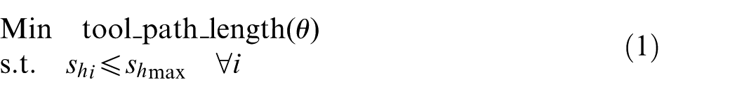
where the optimization variable
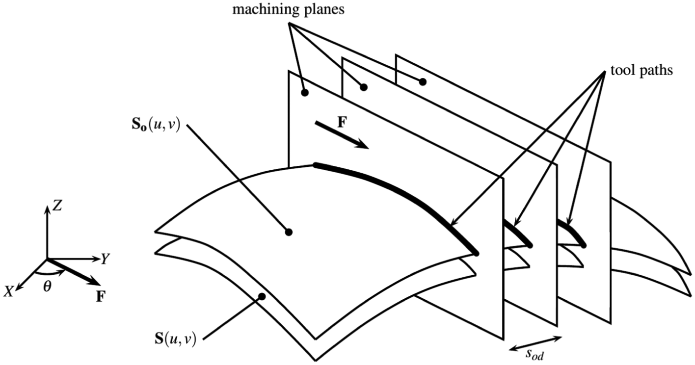
Machining strategy by parallel planes.
Therefore, the computation time of a path planning for the entire surface must be low enough to allow the integration of this process with the goal of optimization. It therefore becomes possible to solve in a reasonable time the optimization problem in equation (1).
Furthermore, this optimization problem is subject to numerous inequality constraints. Indeed for each point of the planed tool paths the maximum scallop height allowed must be respected. The second objective of this paper is to ensure that these constraints are respected. In other words, the procedure we propose must ensure quality.
To ensure both of these objectives are respected we first propose a new procedure to determine optimum machining direction while respecting tolerance. Then, in a test case, we apply this procedure and verify that maximum scallop height is actually respected by measuring the machined part.
Context of this study
A key parameter in the generation of machined scallops is the effective radius of the tool denoted
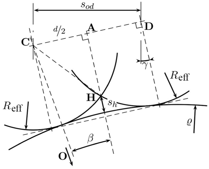
Step-over distance calculation.
Showing that the step-over distance is directly related to the cutter’s effective radius is thus equivalent to showing that distance d depends directly on that effective radius. As proven in Redonnet et al. 22 the distance d can be calculated by
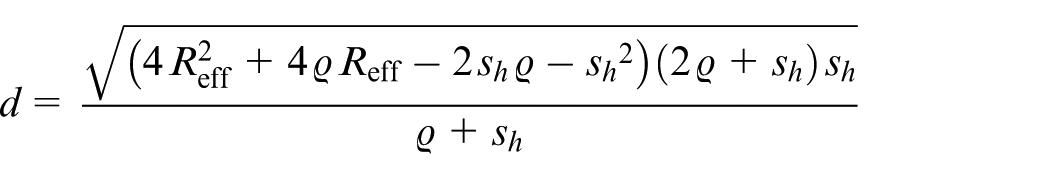
where
For a given machining plane, the position of the adjacent plane is defined by the value of the transverse step-over distance
In a previous study, 22 a novel approach to calculate analytically the effective radius of a torus milling cutter moving in pure translation is presented. This approach is based on the following two lemmas.
Having demonstrated these lemmas, the effective radius of the toroidal cutter can be calculated considering the projection of the torus center circle in a plane normal to the machining direction and the r-offset of the resulting ellipse. The validity of this approach is fully demonstrated in Redonnet et al. 22 It is also stated that this demonstration is only valid for pure translation movement of the cutter.
A simple analytical equation (2) resulting from this study saves considerable time in the calculation of the effective radius of the tool and thus the scallop height resulting from two side-by-side tool paths. Indeed, the only known alternative to accurately assessing the scallop height is through numerical calculation of the intersection between the two envelope volumes of the tool paths. The calculation time is considerably shortened using a simple analytical formula allowing the consideration of applications banned until now due to their cost in terms of computation time.
The parallel planes machining strategy (Figure 3) is used to define each tool path as the intersection of the tool-center surface and a vertical machining plane oriented along an overall machining direction that is called

with
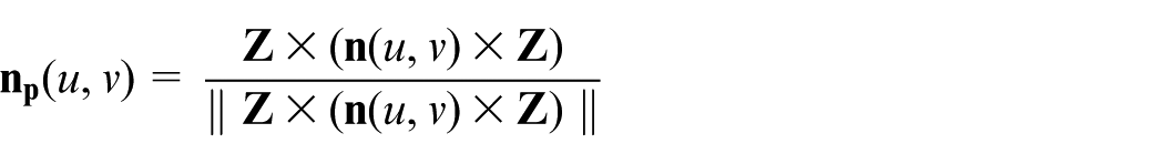
where
For simplicity, we consider the vector
The analytical expression of the effective radius of a torus-end mill moving in translation is 22
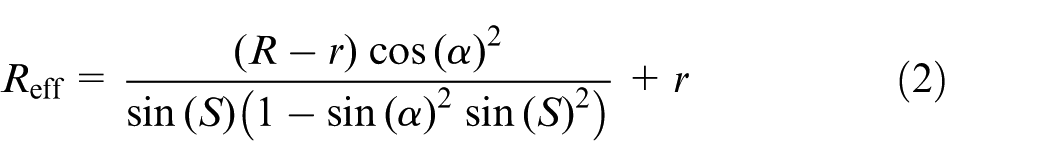
where S is the slope of the workpiece surface at the tool/workpiece contact point and
Optimization methodology and implementation
Optimization algorithm
As posed in equation (1), the problem that is proposed to be solved is a nonlinear constrained optimization problem. The main difficulty is the evaluation of the objective function as it requires the full simulation of a machining planning for the entire surface. Considering i the point index of a given path, and j the index of the path, are defined:
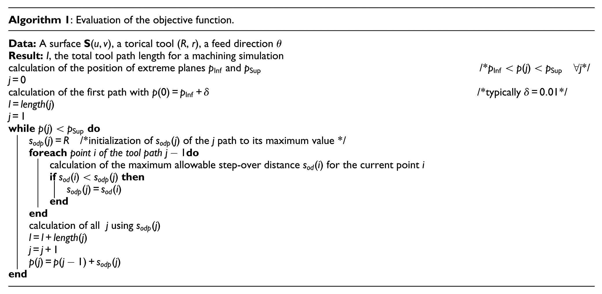
The evaluation of the objective function then proceeds as described in Algorithm (1). This algorithm is also presented as a flow chart in Figure 5.
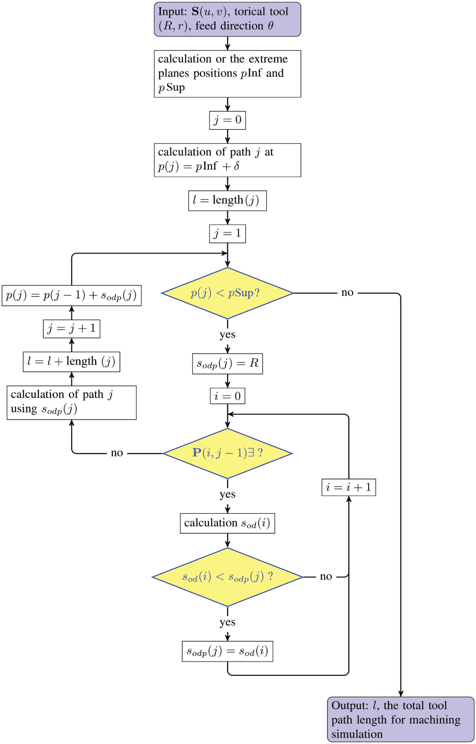
Flowchart representation of the algorithm.
This evaluation process of the objective function effectively enforced all conditions
To carry out the optimization procedure itself, it is then possible to use an unconstrained optimization algorithm. We chose the Nelder–Mead algorithm 23 because it is known for its robustness and efficiency, due, at least in part, to the fact that it does not require calculation of derivatives. Its main drawback, commonly accepted, is that it progresses relatively slowly compared with algorithms including the calculation of derivatives. It may be noted that, in the context of our problem, the evaluation of derivatives requires the full calculation of a machining plan, which significantly lengthens the overall time to resolution.
Furthermore, the optimization procedure described in Algorithm 1 also provides a complete and optimized plan for finishing the surface, which is an advantage over a procedure that would only provide the optimal machining direction.
In terms of computation time, the whole process of optimization/planning requires a few seconds to tens of seconds depending on the chosen parameters. The most influential parameters are as follows.
The scallop height
The required accuracy on the optimization variable
Implementation
In order to determine the starting point of the optimization procedure, a rough estimate of the first objective function is performed for a set of values covering the solution domain. In practice, the objective function is evaluated every 5°, between −90° and +90°, simulating a machining operation with a 0.1 mm scallop height. If it is not exactly realistic for industrial application, this value (0.1 mm) provides very quickly (about 10 seconds) an acceptable starting point for the optimization procedure.
From this starting point, a first simplex is automatically generated and optimization itself begins (see Algorithm 1).
The test environment has been developed in Java.
Application to a real case: Machining a boat propeller blade
Introduction
The determination of the optimal machining direction for end-milling of a free-form surface with a torus-end mill using parallel planes machining strategy allows significantly increased productivity. Of course, the time savings that are to be expected depend largely on the geometry of the surface. For example, the application of the previously detailed optimization procedure to a complex surface from an industrial environment is presented. This surface, taken from a boat propeller measuring 293 mm in diameter (Figure 6), is constituted by the upper surface of a blade (Figure 7). When it is defined by a ruled surface, this type of part can be machined using side-milling process,
24
but this one is defined by an
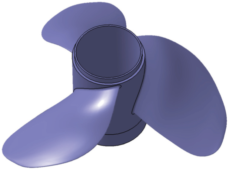
Boat propeller.
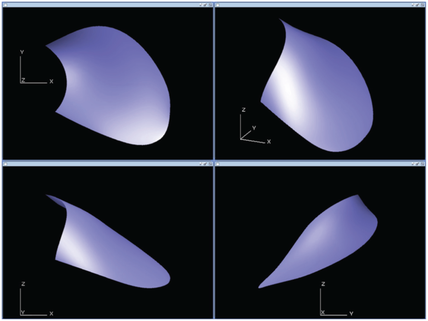
Upper surface of the blade.
Simulations and real part machining were carried out using a torus-end mill of major radius
The manufacture of the workpiece from the trajectories calculated by the optimization procedure has been implemented with a zigzag trajectory plan. Before the finishing operation, a roughing and a contouring phase has been completed (Figure 8).
Contouring and roughing preliminary operations.
The finishing operation was conducted using a spindle rotation of 7950 r/min and a feed-rate of 1600 mm/minute.
Results and discussion
Machining time
Using a 0.01 mm scallop height parameter, the total duration of the optimization process is 116 seconds for the tool (
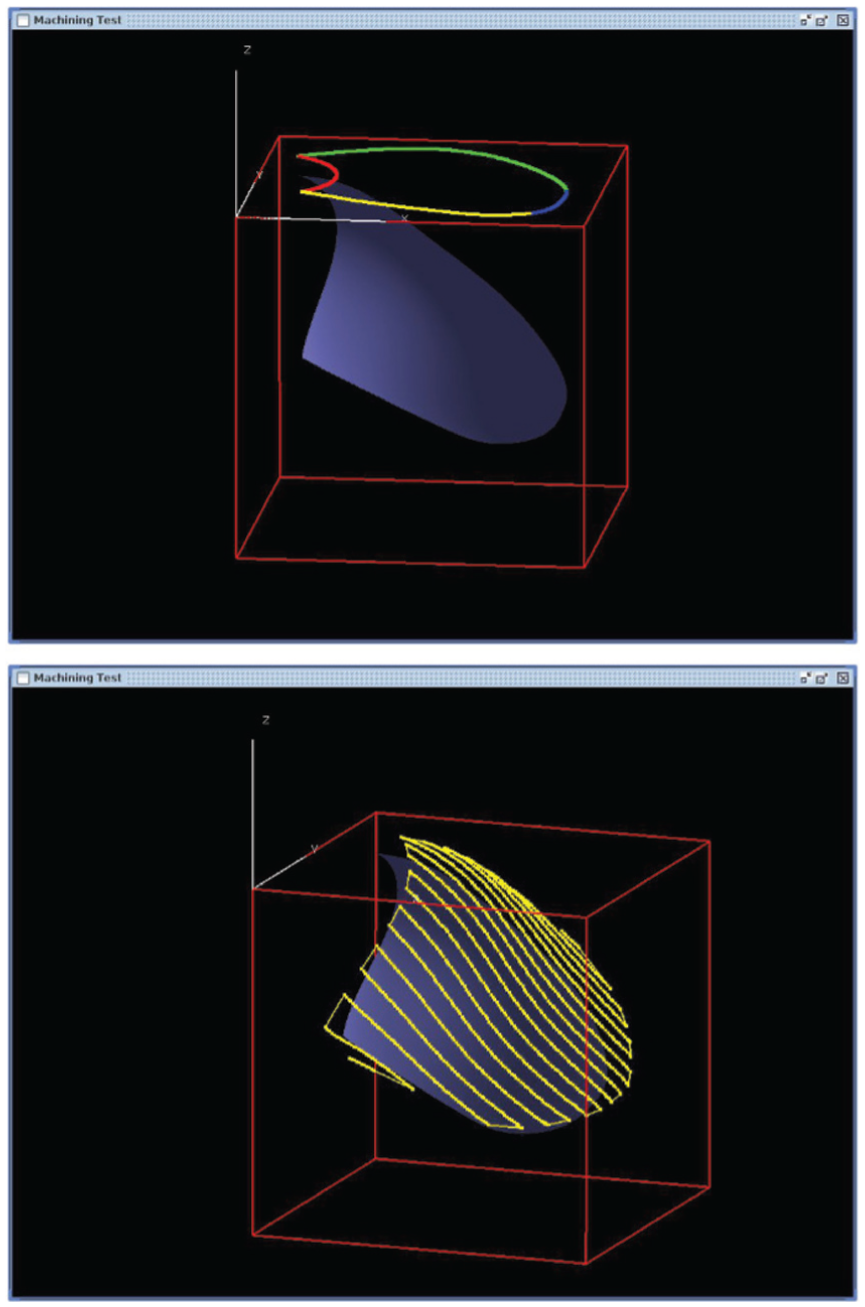
The machining plan obtained by the optimization procedure is shown in Figure 9.
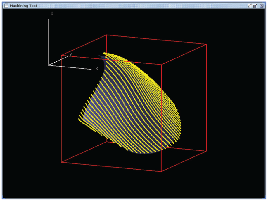
Machining tool path plan along an optimal direction (one path in five is drawn).
Considering the scallop height value (
Using the parameters described above (Subsection Implementation), the total duration of the machining cycle was 8 minutes and 16 seconds. The workpiece so machined is shown in Figure 10.
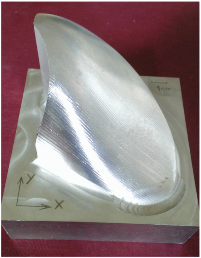
Machined part.
The results presented here can give an idea of the potential gains that allow the optimization of the machining direction during milling of the free-form surfaces using parallel planes strategy with a torus-end mill. The diversity of complex surfaces coming from Computer-Aided Design (CAD) is such that no analysis of the performance of a machining algorithm can be generalized. So the potential contribution of this procedure is necessarily evaluated through an example.
To evaluate the potential gain, the results of the machining planning for the entire domain of the definition of the parameter
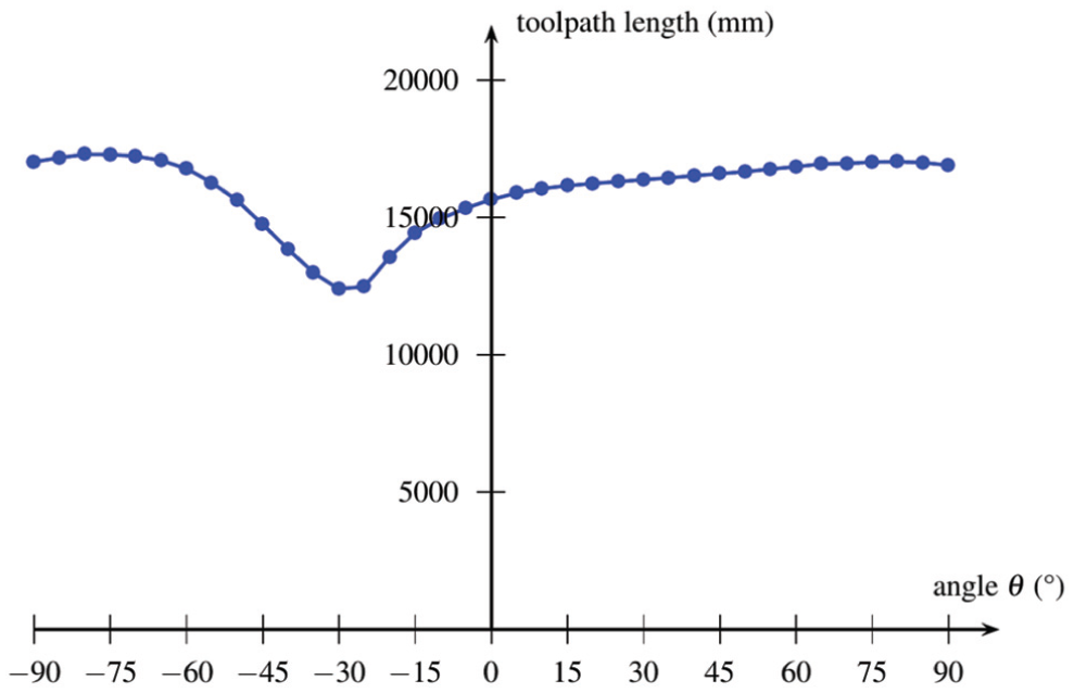
Evolution of the objective function value on the whole domain.
By various tests, it has been found that, for this surface, the total duration of the procedure is about two minutes.
To evaluate the potential gain that prior calculation of the optimal machining direction can offer, the most favorable case and the worst case are compared (Table 1).
Comparison between extreme cases for a single part.
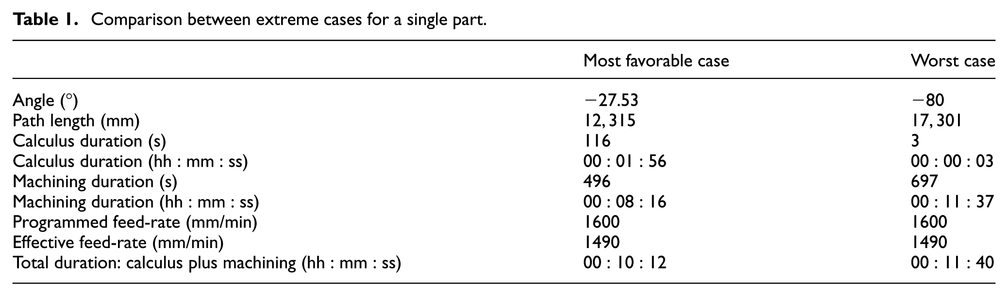
This comparison highlights several interesting points:
For this workpiece, the potential gain can rise up to
For this workpiece, the total duration of the procedure including optimization (calculus plus machining) is less than the total length of the simple machining procedure in the worst case. In other words, the optimization of the machining direction saves time from the machining of the very first part. Of course, the fact that our procedure saves even more time than the series is important. Indeed, the procedure for determining tool paths is performed only once, while the machining time saved occurs on every workpiece. For example, on the workpiece studied here for the realization of a series of 50 pieces, the total time savings could be up to
This example allows highlighting the interest in optimizing the machining direction before the completion of the part machining itself. In addition, the comparison is limited to measurements of time. In terms of manufacturing costs, the hourly computing rate is far less than the hourly machining rate; the interest of the presented procedure is then even more evident.
It should however be noted that the numerical values ??in the presented results include only one example. Since each piece of CAD is special case, no overall performance value can be advanced. The example that is discussed here, however, allows highlighting of the potential value of the given procedure. With this in mind, this surface has several attractive features.
It is an industrial workpiece.
The optimal machining direction is not obvious a priori.
It has wide variations in normal direction.
For all these reasons, this area is representative of the forms commonly encountered in the modeling of molds and dies, so it is a good example to illustrate the performance of the presented procedure.
4.2 Surface quality
To check the validity of the machined part, we conducted a series of measurements at different points of the part. Special attention has been paid to focus the measurements in the most critical areas. Indeed, as mentioned in Subsection Context of this study, during the machining of a curved surface with parallel planes strategy, all the different points of the path do not generate the same scallop height, and it is the most critical point that determines the position of the adjacent plane.
To make these measurements, a 3D optical Alicona Infinite SL was used.
Figure 12 shows one of these measurements results. This figure highlights the scallops that are typical of a free-form surface machining. In this screen shot, the left scallop is fully measured between
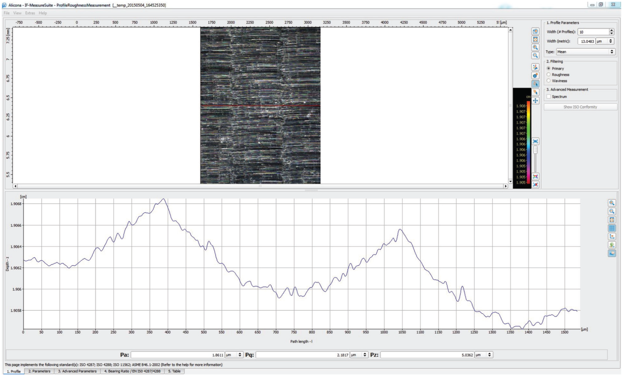
Machined part profile measure.
On the whole part, 10 measurements were made and similar results were found for all these measures, i.e. that tolerance is respected at each measured point. We can therefore say that the tool paths calculated by the presented algorithm (see Algorithm 1) allows the constraints of our optimization problem to be respected (see equation (1)), i.e. maximum allowable scallop height. The validity of the presented optimization procedure is therefore confirmed by experimentation.
Conclusion and perspectives
In this article, a procedure to determine the optimal machining direction using a parallel planes strategy and a torus-end mill is presented. This optimal direction is the one that allows the greatest productivity while respecting the maximum scallop height constraint. This methodology has several advantages. First, it is simple to implement because it is based on a simple optimization algorithm. Also it provides quick results and full tool path planning in the context of machining free-form. This simplicity of implementation and speed make this an easy procedure to integrate into a workflow process.
The optimization procedure we propose has been validated on a test case. This experiment shows the potential gain that can be obtained using it.
For the moment our method is only applied for a parallel planes strategy. We are currently working on improvements to be able to apply this method to other machining strategies. This will be the purpose of future publications. For this publication, we choose the parallel planes strategy because it is widely used in industry (most people choose it because it is reliable and efficient) and the optimization problem is quite simple to state (it depends only on one optimization variable: the feed direction
To improve the procedure that is presented here, it is also planned to integrate the dynamic behavior of the Computer Numeric Control (CNC) machine in order to optimize not the distance traveled by the tool but the total machining time. In addition, it is also proposed to test and/or develop other optimization algorithms in order to improve the computation time.
Footnotes
Declaration of conflicting interests
The author(s) declared no potential conflicts of interest with respect to the research, authorship, and/or publication of this article.
Funding
The author(s) received no financial support for the research, authorship, and/or publication of this article.