
Abstract
The brazeability of automotive zinc-coated steels depends on several factors. These include the morphology of the joint and the welding parameters selected. However, more fundamental material factors such as the composition of the coating, method of coating and coating thickness also have a significant effect. In this study, five commercially available and widely used automotive zinc-coated steels are investigated to assess brazeability. Surface zinc content and the coating type are shown to have a marked effect on the quality of the resulting joint. This is shown by surface analysis of the joint to determine evenness and bridging capability of the filler material and a cross-sectional analysis of the joints. Differences in wettability and contact length of the filler material and zinc-coated steel substrate are observed. It was found that electro-galvanised steel exhibited the best brazeability of the materials investigated here. Wettability of spreading angles as low as 17.3°, most uniform contact length and best bridging capability due to the filler material forming a metallic bond with the substrate were observed. However, pores were present in cross-sections. Galvannealed steel also showed good wetting with no embedded defects. Other steels used (galvanised and magnesium–aluminium zinc steels) presented problems with uniformity, high spreading angles of the filler material and poor bridging characteristics.
Introduction
Low-cost joining methods are sought by automotive manufacturers for joining of plate materials as a viable alternative to high production, high-cost joining processes. Focussed arc tungsten inert gas (TIG) brazing is an approach in joining zinc-coated steel panels in the automotive industry, based on TIG brazing, by filling a gap between two thin panelled zinc-coated steels with a filler material in an argon-shielded environment to prohibit oxidation. This thermal joining technique is used for body in white (BIW) production of ‘A class’ joints. ‘A class’ joints are defined as aesthetically pleasing, visible joints on the outside of the BIW. This approach enables a lower cost production system for low-volume plants compared to laser brazing, which is more suited to high-volume production (20% cost of a full commercial laser system). 1 This process is primarily used for BIW roof joints (shown in Figure 1(a) with an application and Figure 1(b) in a simplified form) and lift-gates. The filler material acts as a wetting agent for the mating surfaces of the joint that leads to formation of a metallurgical bond between filler and the mating surfaces of the parent material. 2 The main goal of using this method is to join the structural steel panels to form the BIW while maintaining the corrosion resistance offered by the zinc coating. 3 The welding plasma, brazing speed and filler wire speed need to be closely controlled to ensure optimum filler wire melting while minimising damage to the zinc coating. The strive to braze and weld thin panel materials in the automotive industry has been reviewed by Kah et al., 4 where the need for reduction in the heat-affected zone and optimisation of energy delivery is discussed. Due to zinc boiling at 907 °C, the area and contact time of heat impact from the plasma are key in ensuring a corrosion-resistant joint. The filler material for this specific process is a copper alloy with 3 wt% silicon additions which is intended to reduce the formation of intermetallics.
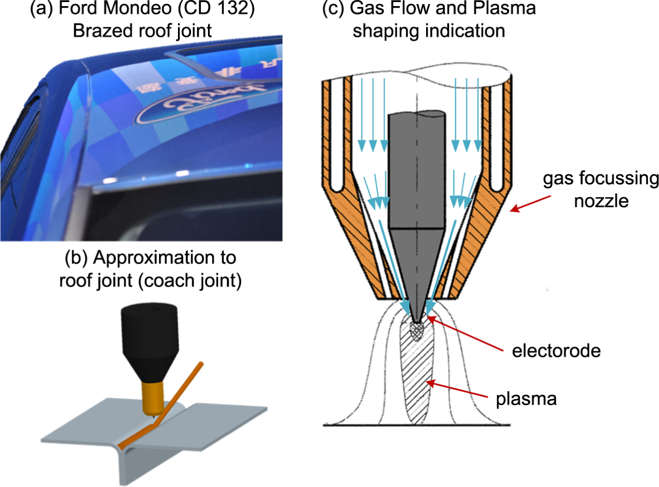
Typical focussed arc TIG brazed application in the automotive industry: (a) roof panel joint of a Ford Mondeo (CD132), (b) schematic of the simplified coach joint used in the roof and (c) the focussing effect of the focussed arc TIG torch used to create the brazed joints.
Focussed arc TIG brazing operates on the principle of TIG welding, where a non-sacrificial electrode creates plasma as a result of electrical discharge with the work while a filler material is fed in from the side. The difference of focussed arc TIG and normal TIG is that the power density and spot size of the arc are optimised for delivering energy densities similar to laser brazing (>106 W/cm2). 5 A conventional TIG torch floods the area with a shielding gas to avoid oxidisation upon solidification 6 and due to the lack of gas focussing the energy delivery is <105 W/cm2. Contrary to that, the focussed arc TIG has a reduced gas exit nozzle, which uses the shielding gas to help shape the plasma and increase the power density through a focussing effect. A schematic of how this system works is given in Figure 1(c).
Zinc-coated steels are commonly used in the manufacture of BIWs to enhance corrosion resistance. 7 This method has been widely adapted in this sector. 8 Coated steels are used for the purpose of reduced cost, simplified material design and recyclability rather than bulk alloys. 9
Coating with zinc alloys protects the surface by both barrier and cathodic protection; the latter being dictated by the electrical activity of the metals. 10 By isolating the steel substrate from the atmosphere, the sacrificial anodic zinc layer will preferentially (cathodically) corrode and maintain steel integrity. 11 Chemical additions to the Zn layer such as Fe, Mg and Al have shown to greatly improve corrosion resistance.12,13
Common zinc coating methods for steels include hot-dip galvanising, electroplating and thermal spraying. 10 Previous studies have shown that an oxide-suppressing coating is necessary to braze steel panels together as the presence of iron oxides on bare steel (BS) will prohibit the filler alloy from wetting and ultimately fail to create a joint. 14 This can arise through the creation of intermetallics, prohibiting a metallic bond with the substrate materials. During wetting of the filler material into the joint, fluid flow is characterised by complex dynamics and dictates the quality of the brazed joint. 15 This is further influenced by the interfacial reactivity phenomena when the liquid filler material contacts the steel interface. Koltsov et al. 14 have investigated this phenomenon with galvanised (GI) steel and electro-galvanised (EG) steel joined by a CuSi3 filler laser brazing. Tests have shown that BS prohibits wetting through the presence of iron oxides. Zinc coatings help in suppressing this and allowing iron silicide to form when creating the joint. A measure of wettability is the contact angle of a liquid interface with a solid interface. 16 Measuring this angle gives an indication of the ability of this liquid interface to maintain contact with the substrate. In case of brazing, through cooling, this liquid (molten filler) will then solidify and bond to the substrate material (parent material). Wettability and corresponding contact angle are given in Table 1.
Contact angle wettability.
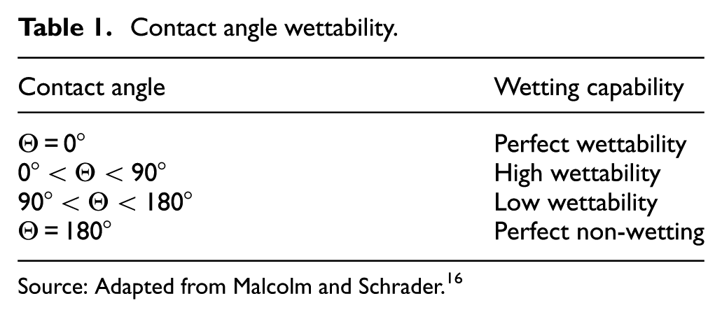
Source: Adapted from Malcolm and Schrader. 16
The aim of this study is to investigate the braze performance of common automotive grade zinc coatings (hot-dip GI, hot-dip galvannealed (GA), EG and EG magnesium–zinc coatings) joined by focussed arc TIG. Due to the novelty of this joining process, the effect on aesthetical factors as well as melting behaviour needs to be determined. This is conducted through varying the input energies and coating types.
Experimental procedure
Brazing trials have been conducted with the focussed arc TIG apparatus while ensuring correct alignment of the torch tilt (0°) and 0 mm offset of wire feeder to torch and torch to joint as per the calibration and setup documentation. The filler wire, for joint creation, used throughout this study is a ∅1.6-mm CuSi3 wire. The machine setup relies on a stationary braze torch and a moving table (Figure 2(a)) on which the steel samples are clamped into a simulated automotive coach joint configuration as described in the schematic in Figure 2(b).
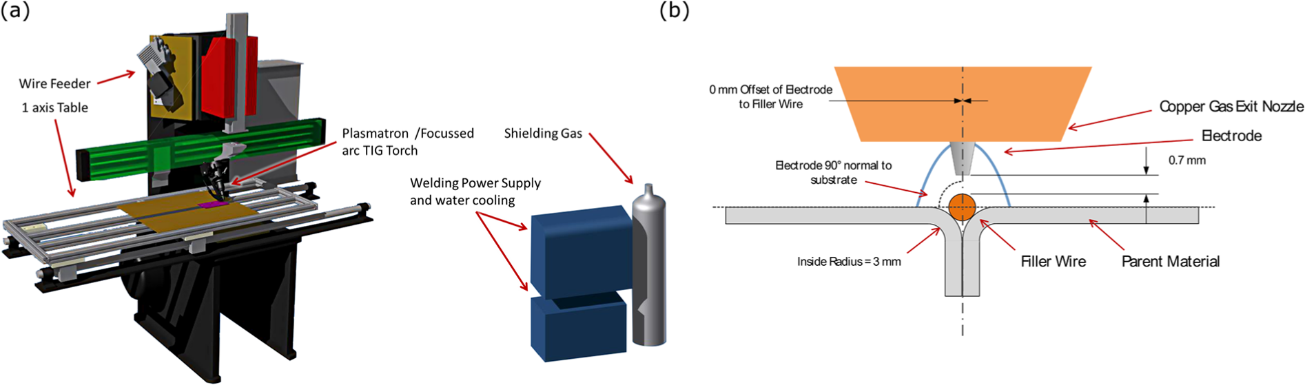
(a) System overview schematic and (b) detailed schematic of the coach joint design used in this study.
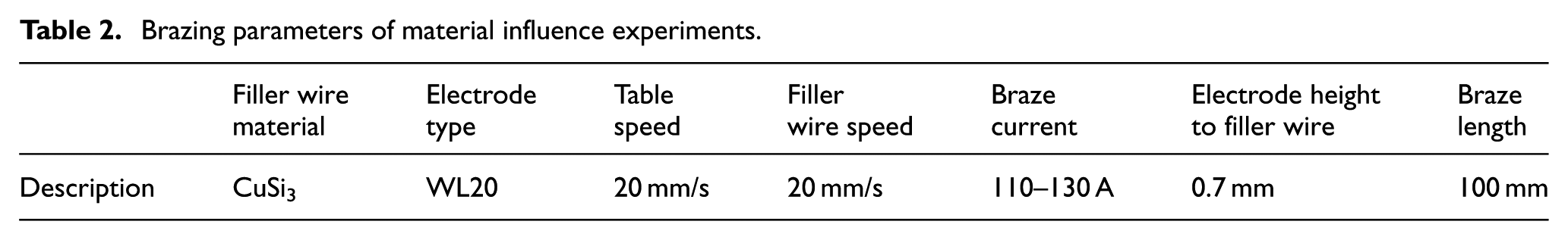
In operation, the filler wire is fed through an external wire feeder assembly (shown in Figure 2(a)) into the joint as detailed in the Figure 2(b). For the purposes of these experiments, the filler wire speed and the moving table speed have been kept constant at 20 mm/s, for a constant contact time of the plasma to the workpiece. Brazed joints are prepared to be 100-mm long. The heat input has been altered through setting the input current only. The braze current was increased from 110 to 130 A in increments of 5 A. Experiments were repeated five times to ensure stability of process. More detailed process parameters are given in Table 2.
Brazing parameters of material influence experiments.
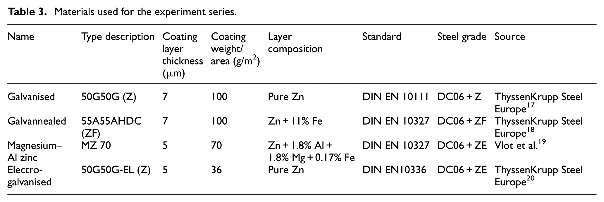
Four types of automotive Zn coatings (coated onto steel grade DC06) and uncoated steel, grade DC06, were tested at the increasing braze currents. Surface coatings have been chosen as they are the common coatings used in the BIW manufacturing industry. Details of the coating alloying elements and coating thicknesses are given in Table 3.
Materials used for the experiment series.
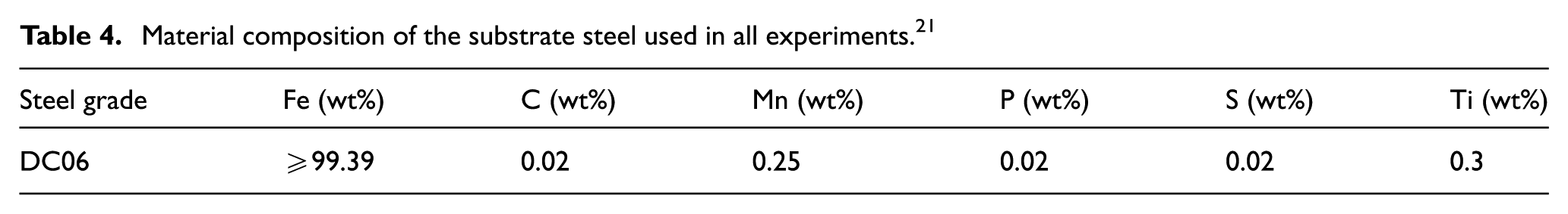
All zinc coatings were produced by deposition on the same substrate steel material, DC06, compositional details of which are given in Table 4. This steel grade is commonly used for super deep drawing operations, ensuring good formability, which enables a complex joint geometry to be created which is typically required in the auto manufacturing industry. 21
Material composition of the substrate steel used in all experiments. 21
Panels were bent into a simplified coach joint configuration with an inside radius of 3 ± 0.1 mm, outlined in the schematic in Figure 2(b). The geometry was closely controlled to ensure good alignment before each braze. The working environment of the braze apparatus was closely monitored with the use of an automated vision tool. This analysis step has been discussed in recent work by the authors. Continuously investigating the electrode geometry has been shown to be important to ensure an optimum focussed arc TIG brazing operation environment. 22 The vision analysis tool measures geometrical alignment and zinc oxide contamination levels on the electrode.
For comparative analysis of this brazing technology, braze current, as is commonly employed in discussions of TIG welding, has been expressed in terms of heat input. In order to be able to calculate heat input of the arc, the efficiency, k, of the power supply (R-Techwelding TIG401) is defined as per DIN EN 60974-1. 23 The arc efficiency for the used power supply is 78.4% (commonly ∼80%). 24 Heat input of the plasma arc has been calculated with
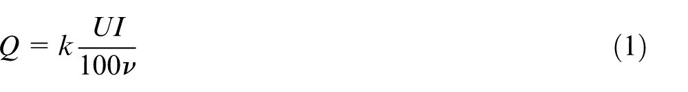
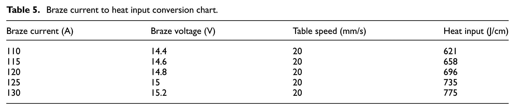
where Q (J/cm) is the heat input, U (V) is the voltage, I (A) is the current, ν (m/s) is the transverse speed and k is the power efficiency of the power supply. Table 5 shows the conversion chart from braze current (I) to heat input (Q) according to equation (1).
Braze current to heat input conversion chart.
Where a cross-section analysis was performed, the samples were prepared with the following: the brazed specimens were sectioned normal to the direction of the braze in an area of steady-state brazing (i.e. disregarding the start and end section of the braze). The sections were then mounted in a thermoset polymer. Subsequently, samples were ground and polished to a 1-µm finish. A 5-s 2% Nital etch was performed to differentially etch the steel to determine material mixing areas within the joint.
Braze surface area measurements and cross-sections of the brazes were analysed with a rack mounted Nikon D3100 DSLR and a Nikon Eclipse microscope with a 10× objective, respectively, yielding a pixel size of 34.9 and 2.3 µm/px. The images are then transferred to and analysed in ImageJ, a Java-based scientific image analysis program.
Data were obtained from cross-sections, as outlined in Figure 3, by defining the following lengths: the bridging gap, A1, shows how far the filler material has spread across to join the substrate panels together. Interface lengths B1 and B2 measure the length of contact of the filler material to the substrate panels. Spreading angles ∠A1B1 and ∠A1B2, the wetting angles of the filler material and the substrate, act as a determination of how well the filler melts onto the steel surface.
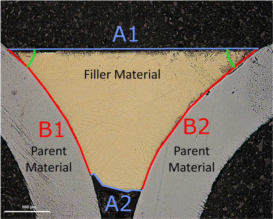
Quality descriptors for cross-section of a coach joint braze.
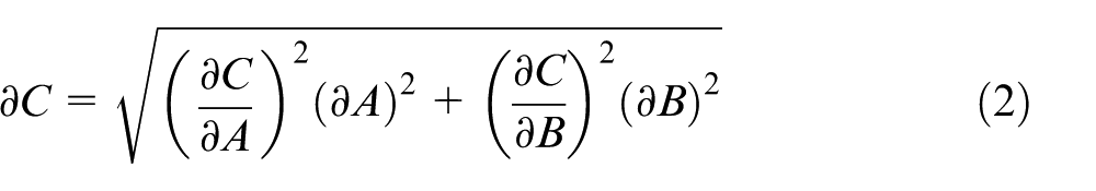
In order to conduct an uncertainty analysis for the areas and lengths measured, specifically determining the accuracy of the measurement, the Kline–McClintock equation for uncertainty calculation was employed.
25
This equation is given in equation (2) and is used to calculate the accuracy for each measurement based on two measurement points A and B, to give a cumulative error of
Results and discussion
Samples of each surface coating were produced with 120-A braze current for a comparison of braze surface area. From a visual inspection of the brazes (Figure 4), it can be seen that both GA and EG steel showed good uniformity, whereas GI, magnesium–Al zinc (MZ) and BS joints were prone to faults such as lack of filler adhesion, linearity and retain braze width. These are highlighted in Figure 4.
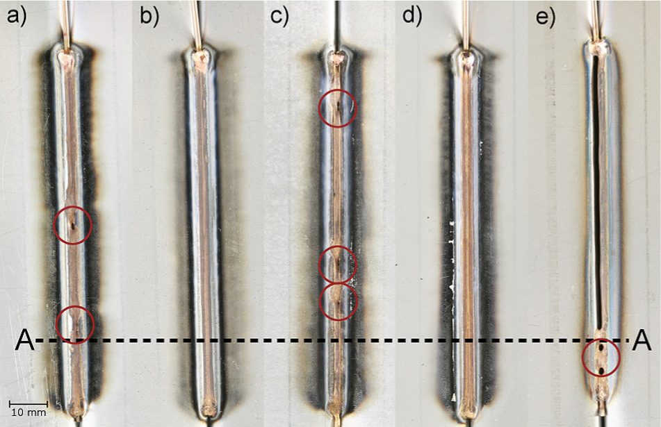
Test brazes with CuSi3 filler on steel grade at a braze current of 120 A: (a) GI, (b) GA, (c) MZ, (d) EG and (e) bare steel with an overlay of where cross-sections were cut from (A-A). Defects are highlighted in red and consist of thinning of the joint and linearity problems (GI, MZ) and complete lack of filler adhesion (BS). No defects are observed in GA and EG samples.
In order to determine how and if the Zn coating layer influences the quality of the joint in focussed arc TIG brazing and, correspondingly, how the filler alloy adheres to the steel surfaces, BS coach joints were created. It can be clearly seen that the BS joint was unsuccessful. The literature proposes this is resulting from the iron oxide layer prohibiting the wetting process and so the filler material does not bridge the gap of the joint. 14 A major or complete lack of filler adhesion was observed in brazing BS over the whole range of braze currents tested in this scope so no further analysis could be performed.
Scaled images of all Zn coating types and braze current combinations have been used to evaluate the top surface of the brazes. This enables a comparative analysis in both an averaged braze width measurement for each material brazed at 120 A (Table 6) and a coverage area measurement, shown in Figure 5.
Average braze width measurements based on 5 specimen and 10 measurements each.
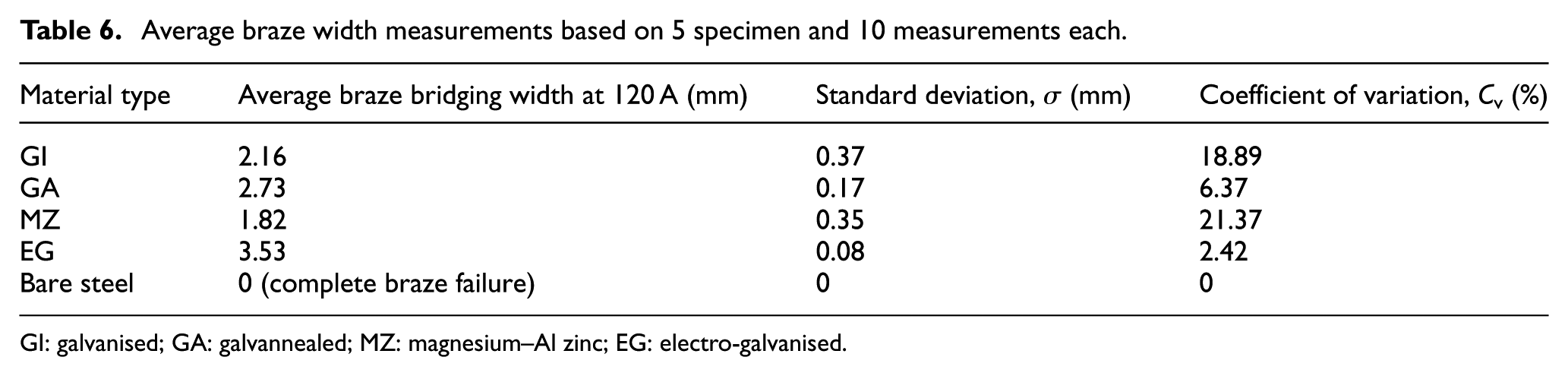
GI: galvanised; GA: galvannealed; MZ: magnesium–Al zinc; EG: electro-galvanised.
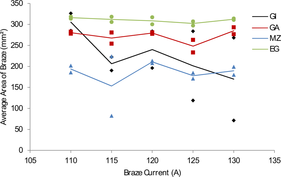
Braze area data for 120-A joints. EG and GA show the highest areas; GI and MZ show an erratic response to a change in braze current. Minimum and maximum braze area data points are displayed to indicate uniformity of melting behaviour.
In this inspection, GI steel showed problems with adhesion (an average of 69% of the joint bridged by filler material) and linearity with all joints showing excessive waviness and holes. MZ steel showed similar problems in that no uniform and linear brazes were obtained. This is a sign of lack of filler adhesion as can be seen in Figure 4(c).
The averaged braze bridging width was determined through 10 measurements each along the 100-mm-long specimen. The coverage area is obtained by measuring the filler area along the whole specimen, leaving out the start and end of each braze.
The surface analysis of the brazed area was employed to quantitatively assess the width of each braze as an indicator of brazeability of each zinc coating.
In order to expand on the braze width measurements, the experiment series was expanded to incorporate all zinc coatings and braze currents as discussed in the experimental procedure. In Figure 5, the minimum and maximum braze area values are displayed to indicate the uniformity of the brazing environment. A greater range in braze coverage area indicates an uneven brazing environment.
The focussed arc TIG process production speed is limited due to the inherent processing environment variables (∼20 mm/s). Tests conducted in the automotive industry have established that although production speed could be increased, the strict quality assurance through standards such as ISO 13919-2 26 (read aesthetic representation of the visible joint) limits the production speed of the focussed arc TIG system. Since this is a direct competitor with laser brazing, where laser brazing can operate at a higher production speed, a cost breakeven analysis is essential in establishing focussed arc TIG as a viable replacement for laser brazing. Figure 6 outlines a breakeven analysis of a simulated lift gate production environment in a German automotive plant. These data are presented in the assumption that the focussed arc TIG is operating at a nominal braze current of 120 A in order to ensure full melting of the filler material.
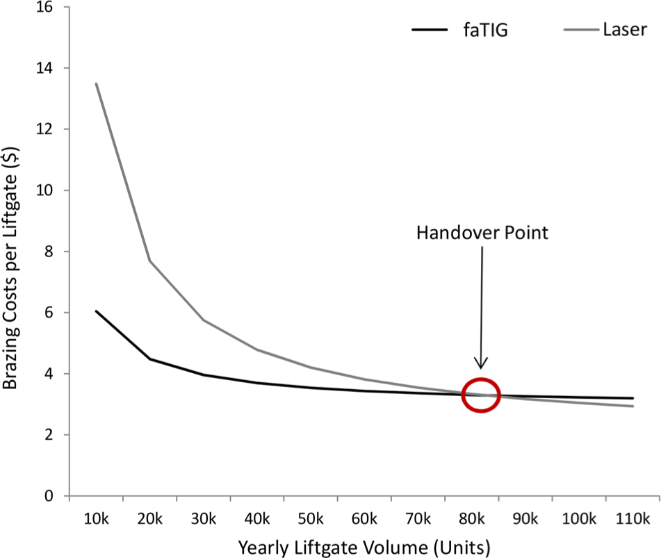
Breakeven cost analysis of focussed arc TIG versus laser brazing in the automotive industry, joining a visible lift gate seam.
From the data shown in Figure 5, it is evident that both GA and EG steels show the most uniformity in braze coverage area over the range of braze currents used. This is backed up by the coefficient of variation of the braze width measurements in Table 6. The main purpose of the filler material is to bridge and join the steel samples together with a maximisation of braze width. Comparing the average braze width at a braze current of 120 A, illustrated in Table 6, it can be seen that EG steel had the best bridging capability across all braze currents, indicating that the filler material readily wetted the steel surfaces and hence maximised the interface length. Its visible filler wire coverage area ranged from 297 to 318 mm2 across the different braze currents. The filler wire coverage of MZ ranged from 82 to 224 mm2, showing an erratic melting behaviour. Having established that the normal working parameters of focussed arc TIG, in industry, is set at 120 A braze current for the given production speed, subsequent samples brazed at this current will be investigated further. Cross-sections of joints created at a braze current of 120 A are presented in Figure 7, showing differences in joint melting for the zinc coatings used. Magnified images of the filler wire interfaces are shown for a comparison of adhesion properties. Inlays of a scanning electron microscope (SEM) analysis are also shown to highlight areas of interest found in the optical microscopy.
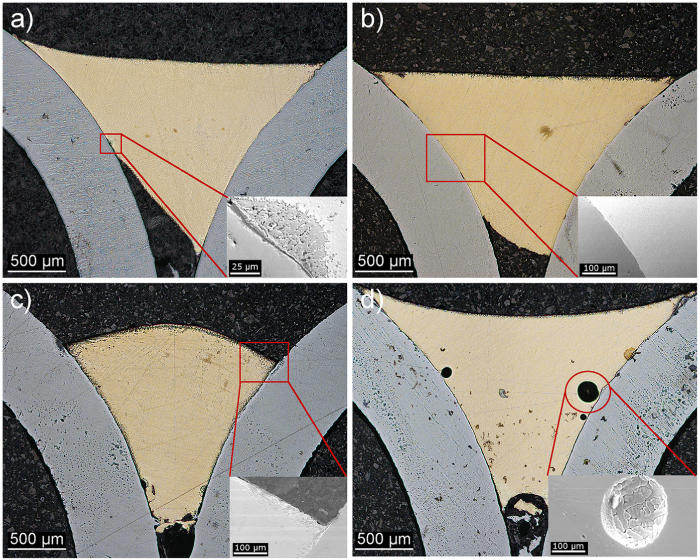
Micrographs of cross-sections of the focussed arc TIG joints with (a) GI, (b) GA, (c) MZ and (d) EG with inlays of an SEM analysis for each.
Figure 7(a) and (b) shows similar filler wire melting behaviour in cross-section for GI and GA steels, respectively. However, the main difference between the steels is that GI has exhibited a thinning of the joint on one side. This is a braze fault that cannot be identified from surface analysis since the thinning occurs sub-surface. GI showed areas at the material interface that with the help of a backscatter electron microscopy analysis has shown to be an inclusion of steel within the filler wire zone.
Comparing Figure 7 with Figure 4, it can be seen that GA steel performs very well under these conditions, showing a uniform steady-state braze quality from the top down view and maximising the filler wire interface to substrate in cross-section. SEM analysis of this sample has shown that there are no material defects. MZ, shown in Figure 7(c), prohibits an even wetting, as can be seen by the convex profile of the joint. This reduces the interface length of the filler wire to the substrate and is unwanted in a structural ‘A-Class’ joint. This can also be seen in the SEM analysis, where the steel to filler wire interface at the corner of the joint is shown. Here, EG steel, presented in Figure 7(d), shows very good wetting as indicated by the concave profile of the joint. This means that the filler material has readily bonded to the substrate. However, only EG joints showed pores in the bulk material. Such formation, especially near the joint interface, is thought to originate from explosive vaporisation of the zinc coating if the coating is unevenly deposited on the steel samples. 27 When the filler material is solidifying in the joint, these pores get frozen into the joint. This is unwanted as these pores can act as crack initiation sites and weaken the strength of the joint. Furthermore, they cannot be identified with a visual inspection, so checking for them increases analysis time and cost.
A quantitative analysis of the cross-sections has been performed for determining the evenness of each braze. This was done, in detail, for all GA and EG joints brazed at different braze currents and for all zinc coatings at a braze input of 120 A as these have shown the highest area coverage across all braze currents described in Figure 5.
A comparative analysis of the interface lengths and change in contact angle of the filler wire and the steel substrate has been performed, shown in Figure 8. The purpose is to study how the energy input affects the material deposition in cross-section and whether that changes the observable wetting behaviour. The error bars given indicate the variation throughout the experiment series, where the main data points are the averaged data. In Figure 8(a), it can be seen that there is a constant offset of the lengths B1 and B2 for GA steel which results from a higher sensitivity of perfect geometrical alignment of the braze apparatus. Electroplated zinc steel shows no such sensitivity. Furthermore, the interface lengths B1 and B2 are maximised; more filler material has contacted the steel substrates. A similar behaviour can be observed when comparing the change in contact angle with a change in braze current for both GA and EG, shown in Figure 8(b). Here, it can be seen that GA’s spreading angles are not symmetrical, indicating a higher sensitivity to the apparatus’ alignment. At the highest braze current in this series, 775 J/cm, material mixing was observed on the B1 side, which is reflected in both graphs of Figure 8. The wetting angle of EG is very uniform and increases with braze current. The low angles signify a good wetting ability of the filler wire to the substrate.
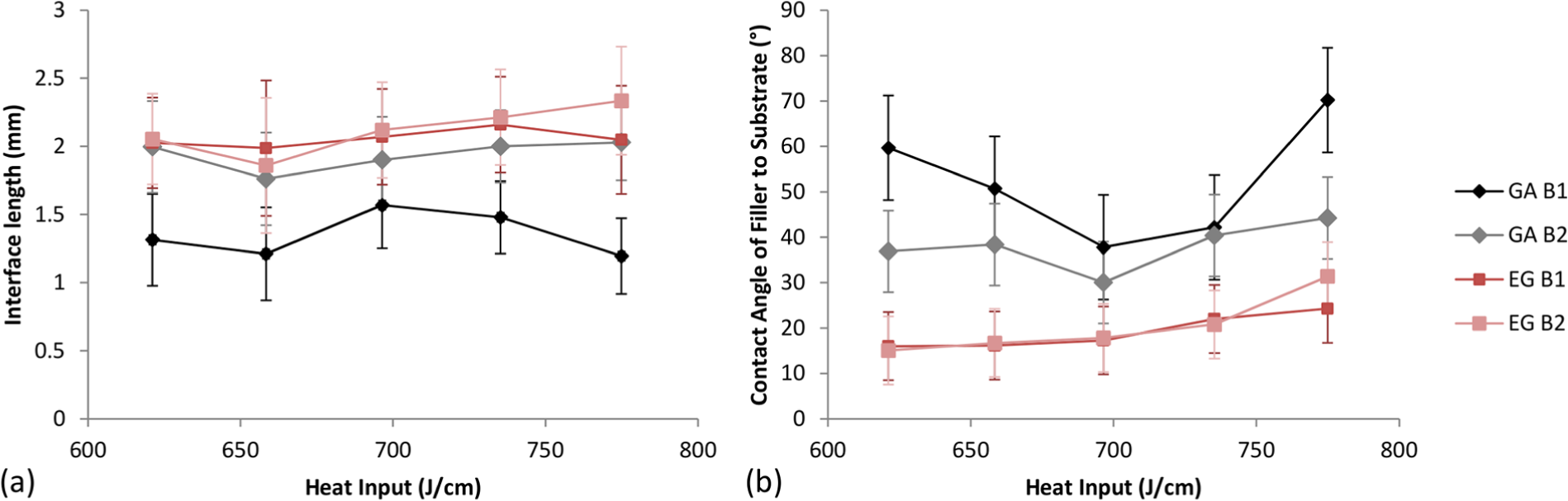
(a) Change of interface length for both GA and EG samples showing an offset in interface length for GA and (b) change in contact angle of filler wire to substrate for the same materials showing a non-linearity of GA.
It should be noted that the GA and EG coatings are similar in composition and thickness. However, it is expected that the degree of alloying with the coating and the substrate may vary as a result of the distinct coating processes. The volatility of zinc and resultant zinc oxide vapour formation will likely lead to poor braze geometry. It is also well known to contribute to pore formation within the braze. While there is a variation in the measures observed here, the authors suggest that the evolution of zinc vapour is higher in the GA specimens. The root cause of this may be the slightly thicker coating.
In order to correlate the data presented in Figure 5, the area measurement of the filler wire coverage of all coating types, an interface length and contact angle comparison are presented in Figure 9. Here, it can be seen that EG shows the best interface length, compared to the other steels that show an imbalance, which indicates poor wettability, where the filler material does not flow evenly into the joint. Figure 9(b) supports this by showing the high contact angle for magnesium–zinc steel (71.5°–80°) and the uneven contact angle for GI steel (20.9° and 43.9° for B1 and B2, respectively). However, GA steel and EG steel show comparatively even melting, where EG has the most uniform behaviour.
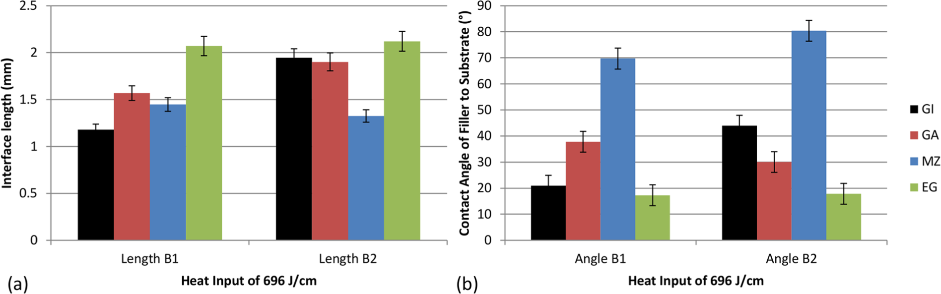
(a) Symmetry of interface lengths B1 and B2 of all zinc coatings at 120 A and (b) contact angle comparison between zinc coating types at 120 A. MZ has the highest contact angles indicating poor melting behaviour. The error shown is the error calculated of the measurement precision.
With the above analyses performed, it is evident that both GA and EG showed good brazeability across the whole range of braze currents chosen for these experiments, whereas GI, MZ and BS showed poor performance.
The GA zinc coating contains 11 wt% Fe and has a thickness of 7 µm. This resulted in good wetting and uniform brazing. The filler wire bridging capability is up to 2.73 mm and the contact angle of the filler wire to substrate is 33.9°. Judging from this, the wetting capability of this material is good. This surface coating is well suited for focussed arc TIG brazing and can be utilised for ‘A class’ joints in the automotive industry.
The EG-coated steel has a thinner coating than GA steel, 5 µm, and lacks the Fe addition. This seems to have no negative impact in that the braze quality and interface length have been very uniform. Additionally, the filler material bridging capability was maximised to 3.53 mm, and with the minimal contact angles of 17.3°, a good melting behaviour was observed. However, pores were observed in the bulk of the joint which means brazes cannot be load bearing and are only suited for aesthetic joints (Class A).
The GI coating is very similar to GA steel in that the coating thickness is identical. However, it is missing the 11 wt% Fe and instead is coated purely with Zn, identical to the EG steel. However, the joint surface quality is poor as indicated by the erratic waviness. This has a negative influence on the braze quality in the form of the creation of holes and lack of filler adhesion. The imbalance of the contact lengths and spreading angles is a sign of poor wettability in this joint configuration. Such a joint cannot be used for automotive applications when joined in the brazing environment discussed here.
MZ zinc steel has a thickness of 5 µm and hence was predicted to yield high-quality joints. However, the chemical composition is optimised for corrosion resistance which impeded wetting of the filler material and low-quality joints were the result. This is shown with the increased average spreading angle of 75.1°.
Conclusion
Focussed arc TIG brazing is a novel process that has the capability to join zinc-coated steels with a CuSi3 filler material. This process is attractive for low-volume production environments due to its lower cost compared to laser brazing, its main competitor. Aesthetic joint surface quality is a main driver in the manufacture of BIWs.
Employing four common zinc coating types, GI (50G50G; GI), GA (55A55AHDC; GA), magnesium–zinc (MZ70; MZ) and electro-plated (50G50G-EL; EG) steel (DC06), simplified coach joints were produced. It was shown that GA steel and EG steel showed the most uniform and maximised joint area at the surface of 2.73 and 3.53 mm average joint width, respectively, at 6.4% and 2.4% variation, respectively.
Faults of brazed joints are predominantly due to a lack of filler adhesion (GI) and linearity (MZ). Over a 10-cm-long braze, GI steel and magnesium–zinc steel failed to create wide brazes at bridging an insufficient 2.16 and 1.82 mm, respectively, at 18.9% and 21.4% variation, respectively.
A cross-sectional analysis was performed on samples brazed at 120 A (energy input utilised in industry) in order to ascertain the bulk filler integrity. It was found that wetting of the filler material to the substrate steels varied greatly. With a good surface bridging capability, GA and EG steels exhibited contact angles of the filler to steel interface below 35°. Koltsov et al. 14 reported on optimised joining capability of steels where the contact angle of the filler material is in the range of 20°–40°. MZ showed poor joining capability with focussed arc TIG, as the contact angles were in the range of 69.7°–80.4°. GI steels showed poor repeatability of both surface joint quality and wetting capability, indicating a non-steady-state brazing environment. It has been shown that both GA steel and EG steel exhibit the best joining capability for focussed arc TIG brazing with a CuSi3 filler.
Footnotes
Declaration of conflicting interests
The author(s) declared no potential conflicts of interest with respect to the research, authorship and/or publication of this article.
Funding
The author(s) received no financial support for the research, authorship and/or publication of this article.