
Abstract
In this article, a novel XYZ nanopositioning stage with hybrid structure configuration is developed to obtain translation motions along the x, y and z directions with high working bandwidth. A novel Z-shaped flexural guidance unit with self-amplification is adopted to generate motions along the x and the z directions by means of differential motion principle. Simultaneously, a right circular-based guidance unit is embedded to generate the motion along the y direction independently. The corresponding working principles in the three directions are detailed in this article. In addition, the statics and dynamics performances of the developed mechanism are investigated by experiments. The workspace of the XYZ stage can reach up to 20.8 µm × 12.2 µm × 23.1 µm with a practical working bandwidth larger than 250 Hz.
Keywords
Introduction
Piezoelectrically actuated compliant mechanisms have been widely employed in various fields, including optical fiber alignment, biological cell manipulation and scanning probe microscopy.1–4 Currently, to satisfy the requirements of complicated operations, a huge number of efforts have been devoted to the design, modeling and control of the positioning stages with multi degrees of freedom, especially the XYZ nanopositioning stages.
From the view of structure configurations, the XYZ nanopositioning stages can be classified into two sorts, one is of serial kinematics and the other one is of parallel kinematics. For example, Yong and Moheimani 2 developed a compact XYZ scanner with parallel kinematics for fast atomic force microscopy, which could record up a 3.5 µm × 3.5 µm image with an acceptable resolution at 625 Hz. Xu and Li5,6 also proposed two XYZ nanopositioning stages with parallel kinematics, which adopted the bridge-type flexure hinges as displacement amplifiers to increase the moving ranges. Differently, Huang et al. 7 proposed a serial-kinematics XYZ nanopositioning stage, where the theoretical maximum output displacement in the three directions is in the range of 9.7–12.5 µm, but the working frequency is less than 100 Hz. Jywe et al. 8 designed a 6-degree of freedom (6-DOF) system to compensate moving errors that the complex structure makes it low resonant frequency. Each sort of the structure may have its unique advantages as well as disadvantages. Generally, the mechanisms with serial kinematics possess the advantages of easy to control and easy to realize the independence movement. However, they also have the disadvantages, such as (1) the redundant movement structure makes it hard to receive higher bandwidth of movement; (2) the error of each kinematic chain adds step by step, which will make the error of the end of kinematic chain larger; and (3) it is hard for the motion of each axis to obtain the same dynamics performance. Besides, for flexure hinge systems, multi DOF motion brings motion crosstalk that brings down the motion accuracy. 9 As for the mechanisms with parallel kinematics, the advantage is that the structure is compact and the closed-loop kinematic chains endow the moving parts with high stiffness, high bearing capacity, high moving bandwidth and so on. However, the disadvantage is that it is hard for this sort of mechanisms to realize the decoupled motions. 10
In this article, a novel XYZ compliant mechanism with hybrid structural configuration is proposed herein. An innovative Z-shaped flexure structure11,12 we previously developed is adopted to achieve motion along the x and z directions, and a typical flexural structure is serially embedded in the XZ stage to generate motions in the y direction. Detailed experimental tests are conducted to investigate the performances of the mechanism.
Mechanical design of the XYZ nanopositioning stage
Schematic of the structure is illustrated in Figure 1. As shown in Figure 1, the entire system consists of a flexural mechanism, three piezoelectric actuators (PEAs) and the base. In order to guarantee the geometrical accuracy of flexural structures, the mechanism is fabricated using the wire electrical discharge machining (WEDM) technique.
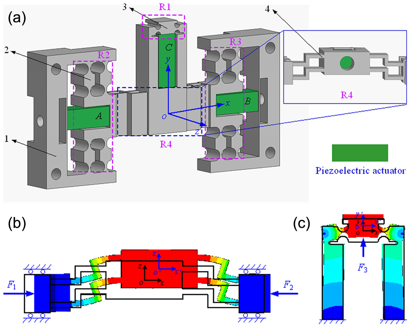
Schematic of the designed XYZ nanopositioning stage: (a) schematic of the designed mechanism, (b) motion schematic of the ZFGU and (c) motion schematic of the RCFH (1, the base; 2, the right circle flexure; 3, the flexural structure guiding the motion in the y direction; and 4, the ZFGU).
As shown in the regions R2 and R3 in Figure 1(a), four groups of parallel and symmetric right circle flexure hinges (RCFHs) are adopted to guide the motions of PEAs in x direction. What is shown in region R4 in Figure 1(a) is the Z-shaped flexure-based guidance unit (ZFGU), which consists of two groups of parallel and symmetric Z-shaped flexure-based hinges (ZFHs). The ZFH can be deemed as serial connections of three simple leaf type flexure hinges, and the shorter one is perpendicular to the other two of relatively longer length. Meanwhile, the lengths of the two longer beams are set as the same, and all the beams possess the same thickness. When the driving forces are exerted to the input ends of the mechanism, the difference between driving forces of the two symmetric driving units A and B will induce motions of the stage in the x direction, obeying the well-known differential moving principle (DMP). Unlike the conventional flexure hinges which directly deliver micro-motions, the long beams of the ZFH cannot shrink straightly when the two symmetric driving units A and B push the two ends of the ZFGU, on the contrary, they will bend to accommodate the space decrease, inducing the motion of the stage along the z direction. As shown in Figure 1(b), assume that the forces applied in the two ends are F1 and F2, the governing law of the two motions can be determined by 8
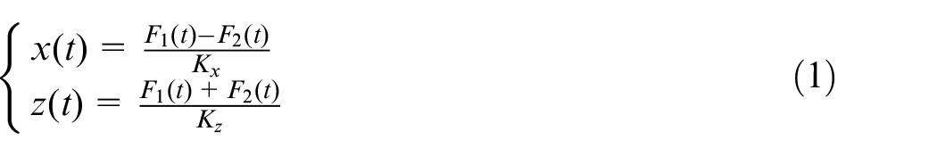
where Kx and Kz are the equivalent stiffness in the x and z directions, respectively. Therefore, the ZFH is more like a motion generator rather than a motion deliver. By choosing proper parameters, the ZFGU possess the amplification ability when it generates the motions in z direction.
Another group of guidance unit with two set of RCFHs is adopted to guide the motions in y direction, as shown in region R1 in Figure 1(a). Specially, a set of U-shaped fillet grooves is designed in the fixed ends of the RCFHs to properly adjust the motion stiffness in the y direction. As shown in Figure 1(c), when the driving force F3 is applied at the input end, the group of RCFHs can directly deliver the motion in y direction. Thus, the novel simple mechanism can generate motions in x, y and z direction with a hybrid structural configuration.
Experimental investigation
The photo of the developed 3-DOF nanopositioning stage is illustrated in Figure 2. As shown in Figure 2, the PEAs are embedded into the driving structures of the mechanism to achieve impact structure sizes. Capacity transducer with four measurement channels (Micro-sense II 5300) is chosen for dynamic position measurements. Three piezoelectric stack actuators (P-880.51, Polytec PI, Inc., Germany), which measures 7 mm × 7 mm × 18 mm, are employed for the mechanism. The amplifier module PI E-617 with a nominal amplification factor 10 ± 0.1 is chosen to amplify the driving signal of the PEAs. The open-loop mode of Power PMAC control card is utilized to generate excitation signals with various wave forms for the PEAs, and the measured displacement signals are gathered through the Power PMAC control card sampled at 0.45 ms. To reduce external disturbances, all the experiments are carried out on a vibration-isolated air-bearing platform Newport RS4000. The measurement noises of the three testing channels are 4.3, 3.8 and 3.5 nm Root-Mean-Square (RMS), respectively.
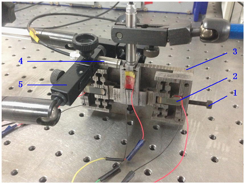
Photograph of the XYZ nanopositioning stage (1, preloading screws; 2, piezoelectric actuators; 3, the base; 4, probes of capacity transducers; and 5, clamp holders).
Statics performance tests
As presented in equation (1), the motions along the z-axis direction will be determined by the sum of the driving forces F1 and F2, while the motions along the x-axis direction will be determined by the difference of the two driving forces. In addition, the motions along the y-axis direction will be independently determined by the driving force F3 which is produced by the driving unit C. Two identical harmonic driving voltages with 100 V amplitude (which is the maximum allowable voltages of the PEAs) and 2 Hz frequency are applied to the two PEAs of driving units A and B to investigate the stroke of the mechanism along the z-axis direction, resulting in the response shown in Figure 3(a). Meanwhile, the deviations in x and y directions during the process is also recorded and illustrated in Figure 3(b). Similarly, the two same driving voltages but with 90° phase difference are applied to the same PEAs to investigate the stroke along the x direction and the induced deviations in z and y directions are shown in Figure 3(c) and (d). To investigate the stroke along the y direction, a harmonic voltage with 100 V amplitude and 1 Hz frequency is independently applied to the PEA of the driving unit C, and the obtained responses are illustrated in Figure 3(e) and (f).
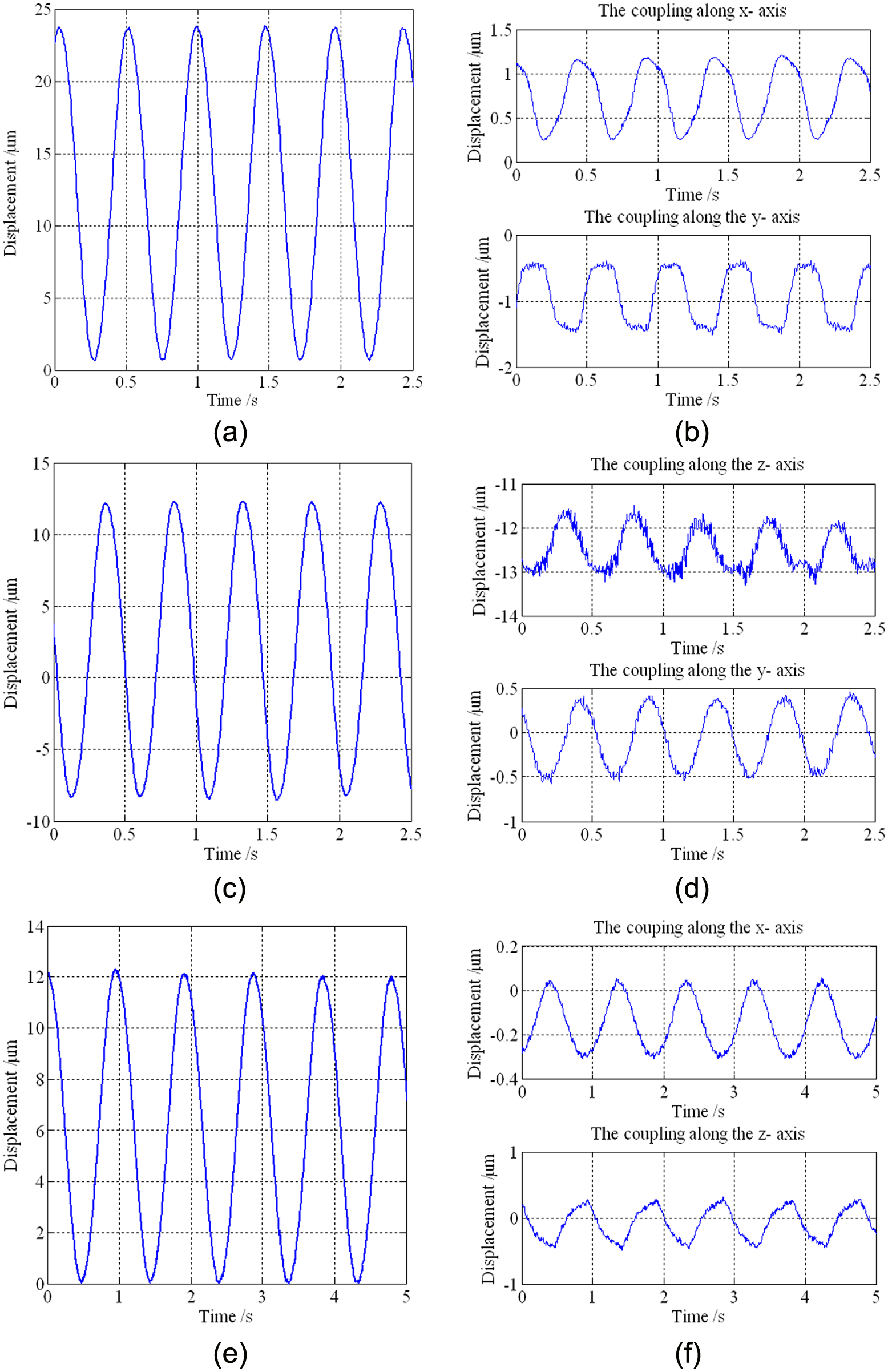
Moving features of the mechanism: (a) the response along the z-axis, (b) the coupling along the x- and y-axes, (c) the response along the x-axis, (d) the coupling along the z- and y-axes, (e) the response along the y-axis and (f) the coupling along the x- and z-axes.
As shown in Figure 3(a), the stroke of the mechanism in the z-axis can reach up to 23.1 µm. Comparing with the stroke (15 µm) of the actuator, the amplification ratio of the ZFGU in the mechanism can be determined as 1.54. It should be noticed that the practical ratio may be higher than 1.54 due to decreased output motions of the PEAs caused by the preloading effects and the input stiffness of the mechanism. As shown in Figure 3(b), the peak-valley value of the induced coupling along the x- and y-axes are 0.91 and 0.87 µm, which are 3.94% and 3.77% of the stroke, respectively. As for the motions along the x-axis direction shown in Figure 3(c), bi-directional motions are well achieved, ranging from −8.43 to 12.38 µm. The asymmetry may be caused by various factors such as inconsistent properties of the employed PEAs, inconsistent preloads of the two PEAs, structural asymmetries induced by manufacturing errors and so on. As shown in Figure 3(d), the peak-valley value of induced coupling along the z- and y-axes are 1.03 and 0.82 µm, which are 4.95% and 3.94% of the stroke. As shown in Figure 3(e) and (f), the stroke of the mechanism along the y-axis can reach up to 12.2 µm, and the peak-valley value of induced coupling along the x- and z-axes are 0.34 and 0.57 µm, which are 2.79% and 4.67% of the stroke. What has been discussed above shows that the developed XYZ nanopositioning stage has significant decoupling properties.
Dynamics performance tests
By conducting Fourier transform of the response of the sweep frequency signals, the amplitude–frequency response (AFR) of the three moving directions are obtained. As shown in Figure 4, the resonant frequencies of the x, y and z directions are 870, 1030 and 840 Hz, respectively.
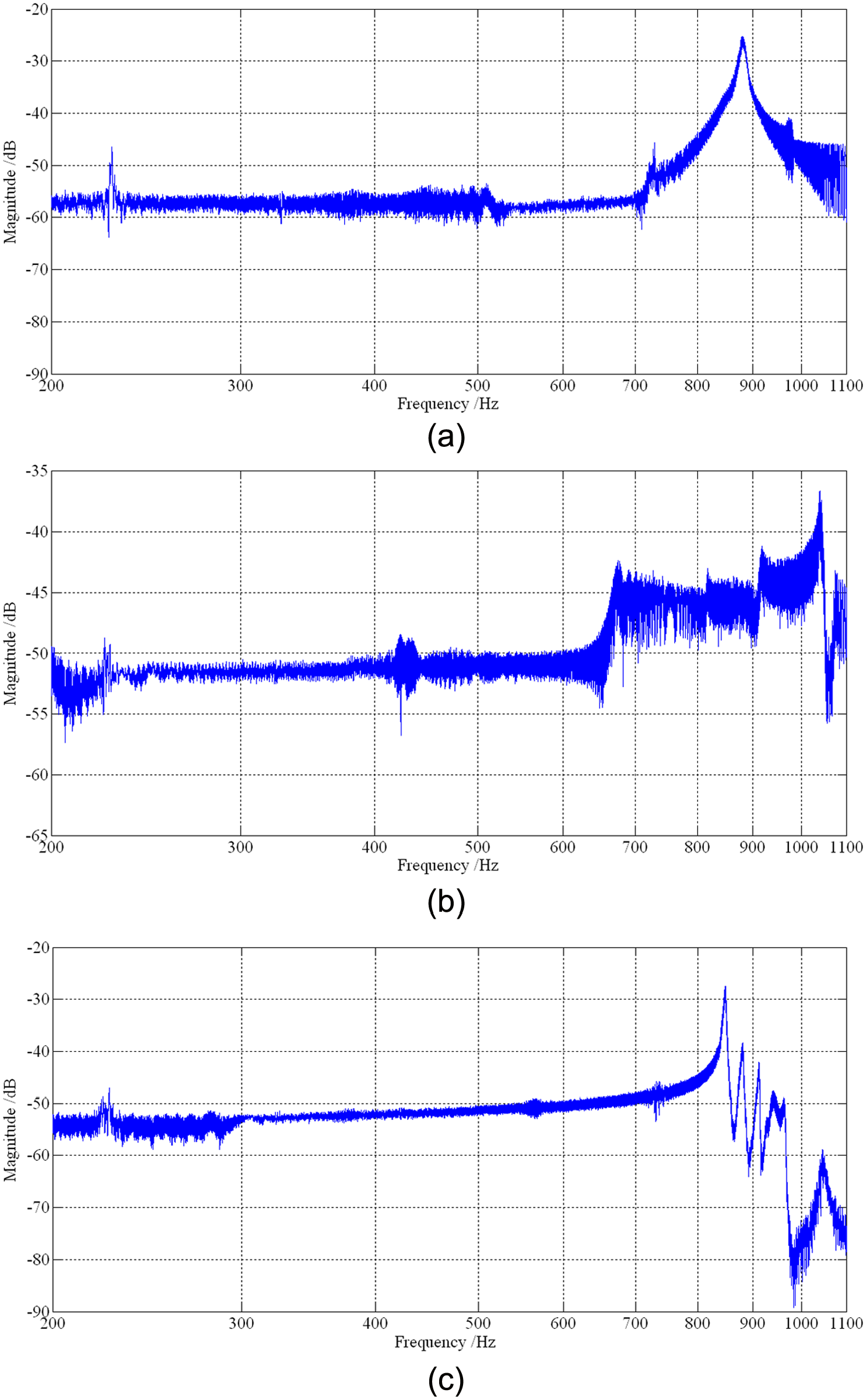
AFR characteristics of the XYZ nanopositioning stage: (a) AFR of the x-axis, (b) AFR of the y-axis and (c) AFR of the z-axis.
To achieve nano-level positioning accuracy of the stage, the resolutions of the three moving axes will be a key performance criterion. In this article, the stair excitation signals with properly small intervals are employed to test the resolutions of the mechanism, resulting in the responses illustrated in Figure 5. As shown in Figure 5, the resolutions along the x-, y- and z- axes are 10, 12 and 10 nm, respectively. The results indicate that the developed XYZ flexural mechanism can realize the nano-level positioning.
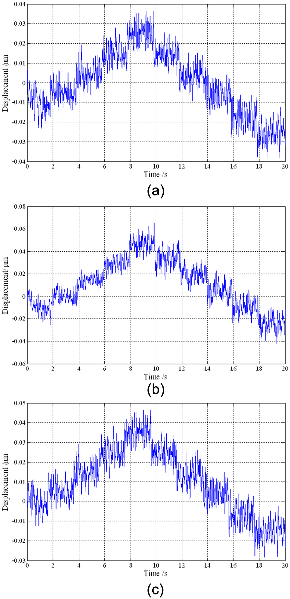
Resolutions of the mechanism along the three moving directions: (a) resolution along the x-axis, (b) resolution along the y-axis and (c) resolution along the z-axis.
Conclusion
A novel XYZ positioning stage with hybrid structure configuration is proposed in this article, and the unique working principles are detailed. Experimental tests are conducted to investigate the performances of the mechanism. The obtained strokes in x, y and z directions are 20.8, 12.2 and 23.1 µm with resolutions of 10, 12 and 10 nm, respectively. By means of the sweeping tests, the resonant frequencies in the three directions are, respectively, 870, 1030 and 840 Hz, suggesting a practical working bandwidth of larger than 250 Hz.
Footnotes
Declaration of Conflicting Interests
The author(s) declared no potential conflicts of interest with respect to the research, authorship and/or publication of this article.
Funding
The author(s) disclosed receipt of the following financial support for the research, authorship, and/or publication of this article: This work is jointly supported by the National Natural Science Foundation of China (No. 51305162) and the Department of Science and Technology of Jilin Province (20130522155JH; 201201026).