
Abstract
The Arctic region is expected to play an extremely prominent role in the future of the oil and gas industry as growing demand for natural resources leads to greater exploitation of a region that holds about 25% of the world’s oil and gas reserves. It has become clear that ensuring the necessary reliability of Arctic industrial structures is highly dependent on the welding processes used and the materials employed. The main challenge for welding in Arctic conditions is prevention of the formation of brittle fractures in the weld and base material. One mitigating solution to obtain sufficiently low-transition temperatures of the weld is use of a suitable welding process with properly selected parameters. This work provides a comprehensive review with experimental study of modified submerged arc welding processes used for Arctic applications, such as narrow gap welding, multi-wire welding, and welding with metal powder additions. Case studies covered in this article describe welding of Arctic steels such as X70 12.7-mm plate by multi-wire welding technique. Advanced submerged arc welding processes are compared in terms of deposition rate and welding process operational parameters, and the advantages and disadvantages of each process with respect to low-temperature environment applications are listed. This article contributes to the field by presenting a comprehensive state-of-the-art review and case studies of the most common submerged arc welding high deposition modifications. Each modification is reviewed in detail, facilitating understanding and assisting in correct selection of appropriate welding processes and process parameters.
Keywords
Introduction
Most large-scale engineering machinery and structures for the Arctic are related to the oil and gas industry. Other emerging industrial applications in the Arctic are wind farms and other renewable energy structures. 1 There is a tendency to use steel of higher strength to reduce the thickness of steel plates (up to 30%–50%) and, therefore, the weight of the structure without sacrificing strength or weldability, to allow easier transportation and installation, making the structure overall more cost-efficient. 2 Currently, industrial Arctic offshore stationary structures and floating drilling units typically use steel plates up to 70 mm thickness; however, some elements can be up to 130 mm. Icebreakers are built from plates of thicknesses up to 60–70 mm. 3 The welding of 20- to 40-mm-thick high-strength steel (HSS) plates presents a wide range of challenges, such as overcoming the tendency for brittle failure and decreasing the welding time. 4 Therefore, there is a call for more efficient welding processes.
The submerged arc welding (SAW) process is one of the most cost-efficient processes for welding thick steel plates. It is frequently used welding method in the shipbuilding production, as it provides high productivity (this work uses the deposition rate as an indicator of productivity) and delivers superb weld quality.5,6 The SAW process can be further modified in order to achieve higher deposition rate, and comparison of these modified approaches is the focus of this article. This article will review and compare narrow gap (NG) SAW, multi-wire SAW, and SAW with metal powder additions.
Requirements for steels and welds in Arctic conditions
Nowadays, the properties required of steels structures for the Arctic oil and gas industry are more stringent than ever as Arctic structures and their welded joints must withstand the harsh low-temperature environment, and awareness of the possible impact of major industrial accidents in the region has spread. These requirements include low-temperature toughness and strength, excellent weldability with lower preheat temperature, and higher welding productivity. 4
Low temperatures in the Arctic may approach −40 °C or lower temperatures and be at that level for continued periods. Thus, in general, the required service temperatures for structures and ships should be taken as −60 °C. For most Arctic structures, the design temperature should be lower than −40 °C, for example, for the first Arctic offshore platform, Prirazlomnaya, it was down to −50 °C. The design temperature for planned offshore structures for operation in ice-covered basins of the Arctic should be about −60 °C, and for structures in open basins, the design temperature can be −35 °C. 7 Even though long Arctic winters have a profound effect on the ductility of carbon steels, generally most structural steels easily satisfy toughness requirements at such temperatures. However, welded parts are much more sensitive to low-temperature fracture toughness issues. 8 Especially, welded metal and heat-affected zone (HAZ) of the weld often demonstrate insufficient toughness at low temperatures.9,10
In order to ensure safe and reliable operations at such low temperatures, materials and especially welding joints should be tested. Presently, the most common criterion for cold-resistance determination of steels and welds is the Charpy V notch impact energy test. Generally, according to most of the standards, an impact value requirement is about 10% of steel yield strength at the design temperature. 11 Various factors contribute to Charpy impact test values. These factors include the amount of welding passes, grain size of austenite before welding, the volume fraction of ferrite phases, and the acicular ferrite (AF) lath width.
Another method to determine the cold-resistance properties of steels and welds is crack tip opening displacement (CTOD) testing. The CTOD test is more precise than the Charpy V notch impact energy test as the CTOD test uses full-thickness specimens. Common CTOD values demanded of cold-resistant steels range from 0.1 to 0.3 mm; 12 however, the required values can vary depending on the steel type and the importance of the construction element.
Specific requirements for testing the base metal and welds of structures are listed in Table 1, which compares the requirements of the most commonly used standards for Arctic conditions. It is hard to set accurate required values for Charpy tests, as the specimens are smaller than the steel plate thickness used. Some standards, for example, Norsok M-001 or Russian Maritime Register of Shipping, additionally use the CTOD test, which is more accurate but more expensive.
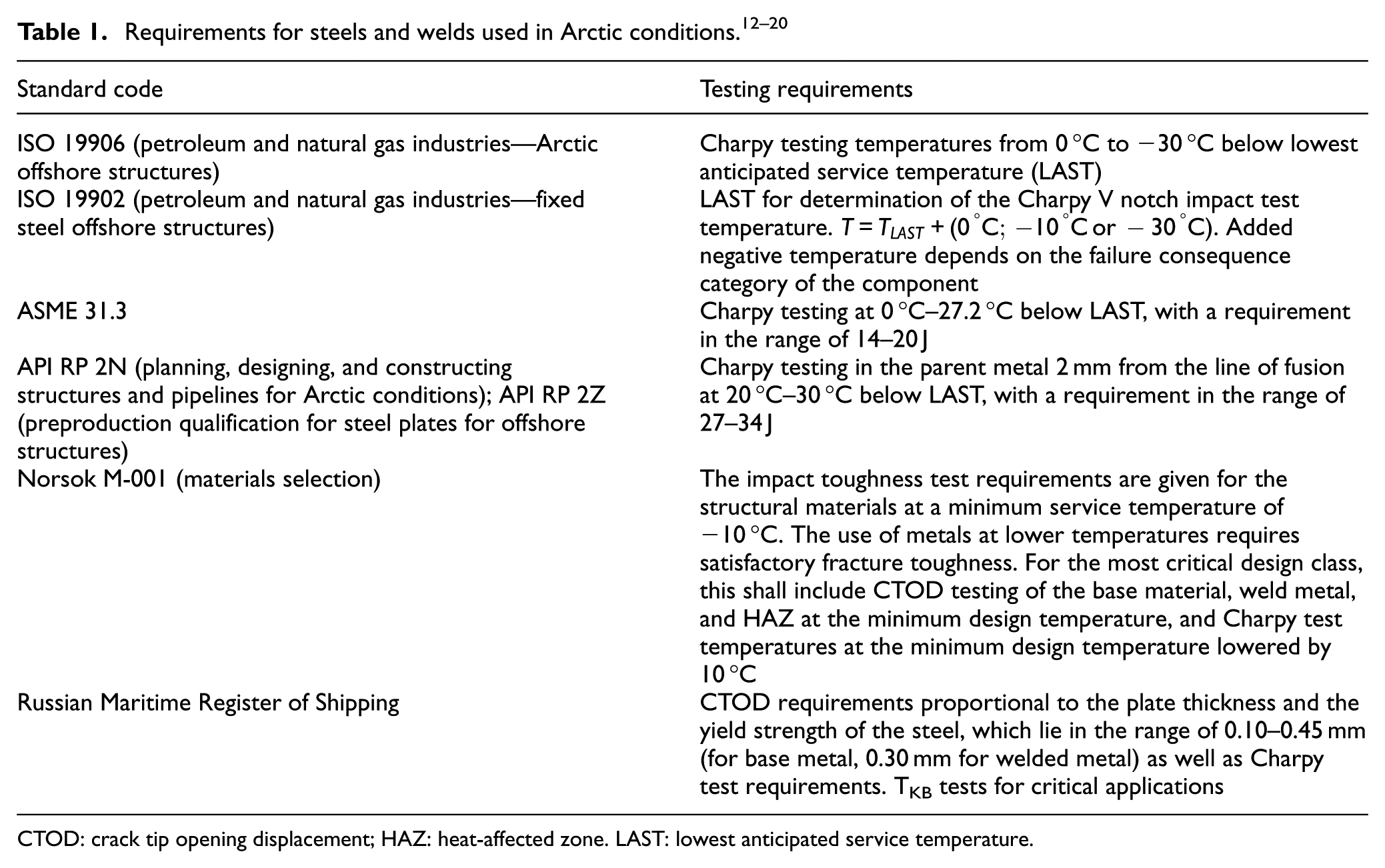
CTOD: crack tip opening displacement; HAZ: heat-affected zone. LAST: lowest anticipated service temperature
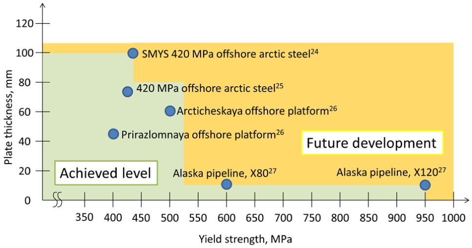
Generally, welded steel passes Charpy tests more often than CTOD tests, and difficulties in meeting CTOD values hamper the application of welded HSSs of large thicknesses. The most critical part for meeting CTOD criteria is the coarse-grain component of HAZ. It has been found that AF is the most desired microstructure in the weld metal. 8 The research further shows that titanium-boron type of welding materials for low temperatures produces a large amount of AF in the weld area. 4 These findings have led to the development of steels with yield strength of 500 MPa and with acceptable CTOD properties of welds in extreme low temperatures and with plate thicknesses of 80–100 mm. 21 Other steel grades have also been developed for Arctic service, and Figure 1 shows welded steels that have achieved values of Charpy (−60 °C) more than 40 J and satisfactory CTOD values (up to 0.35 mm at −60 °C) and that were used in recent Arctic offshore projects. 7 Additionally, Figure 1 indicates the area of possible future advances in steels development.
Arctic shipyards are interested in the development of thick HSS plates of increased tensile strength to decrease the weight and cost of structures and icebreakers. However, with increase in tensile strength, ductility drops and welding become more difficult. Generally, steels with yield strength of up to 500 MPa are used in shipbuilding applications. Welding is typically carried out with heat input of up to 2–2.5 kJ/mm, as higher heat input is detrimental for welds with low-temperature performance. Other major challenges associated with welding in the Arctic region are residual stress control and failure and fracture of welded joints due to cold cracking and severe deformation.26,27 Therefore, the primary industrial interest is to gain higher productivity without increase in heat input.
Welding processes and methods
A wide range of advanced and conventional welding processes has been used for the construction of Arctic structures. In the context of the strict strength criteria and thick plates and tubes demanded of Arctic structures and ice-going vessels, a welding process with a high deposition rate is extremely beneficial, as it reduces the time (number of welding passes) and the cost of manufacturing. 28 SAW with its different modifications meets the need for a high deposition rate, and the SAW process is more profitable than gas metal arc welding (GMAW) on large thicknesses as well as demonstrating excellent weld quality. 29 The increase in deposition rate of SAW can be achieved by different approaches, such as using higher heat input by increasing current, increasing the speed of travel while keeping heat input on the similar level, welding with a longer wire extension length, and using multiple electrodes or metal powder addition.
High heat input allows reducing the amount of passes to form the welded joint. Additional advantage of high heat input is the reduced requirements to the groove preparation. However, an increase in heat input is in most cases connected with an increase in the dilution of the base metal and decreased cooling rates, which can lead to the formation of a coarse grained microstructure and therefore brittleness at low temperatures. Increasing the speed of travel while maintaining heat input allows increasing the deposition rate; however, the issue of undercutting defects arises when the travel speed reaches a certain value.
Multiple electrode welding allows weld with high speed of travel and without undercutting defects. 2 The other way to increase the deposition rate is by supplying metal powder to the weld pool. In addition, it is possible to reduce the weld joint area in order to make manufacturing process more efficient, as it is done in narrow gap welding (NGW). This article will review and compare NG SAW, multi-wire, and metal powder addition welding.
NG SAW
NG SAW is attractive with thick sections in repetitive fabrication, for instance, the fabrication of foundational piles for offshore structures.7,27 NGW is best applicable for circumferential or longitudinal joints of thick HSS pipes and plates. 30 Additionally, thanks to NG SAW all-position capability, it is well suited for large structures, such as shipbuilding applications, where changing position is difficult. NG SAW is usually feasible for plate thickness exceeding 50 mm (to replace double-sided welding), the gap width in most cases is up to 16 mm, and electrodes of 2–5 mm diameter are used. 31 With U-type or V-butt grooves, NGW can be carried out by multi-pass SAW with plate thicknesses up to 300–400 mm. NGW is widely applicable with multiple welding electrodes, for instance, the tandem welding head is commonly used.32,33
During edge preparation for NGW, fewer surfaces need to be created compared to conventional joint preparation. The NGW joint walls should be almost straight; therefore, less machining or cutting is required. Moreover, the one-sided butt NGW arrangement helps to avoid linear misalignments, as opposed to two-sided X groove preparation. However, edge preparation requires a high level of precision, which leads to additional costs. 30
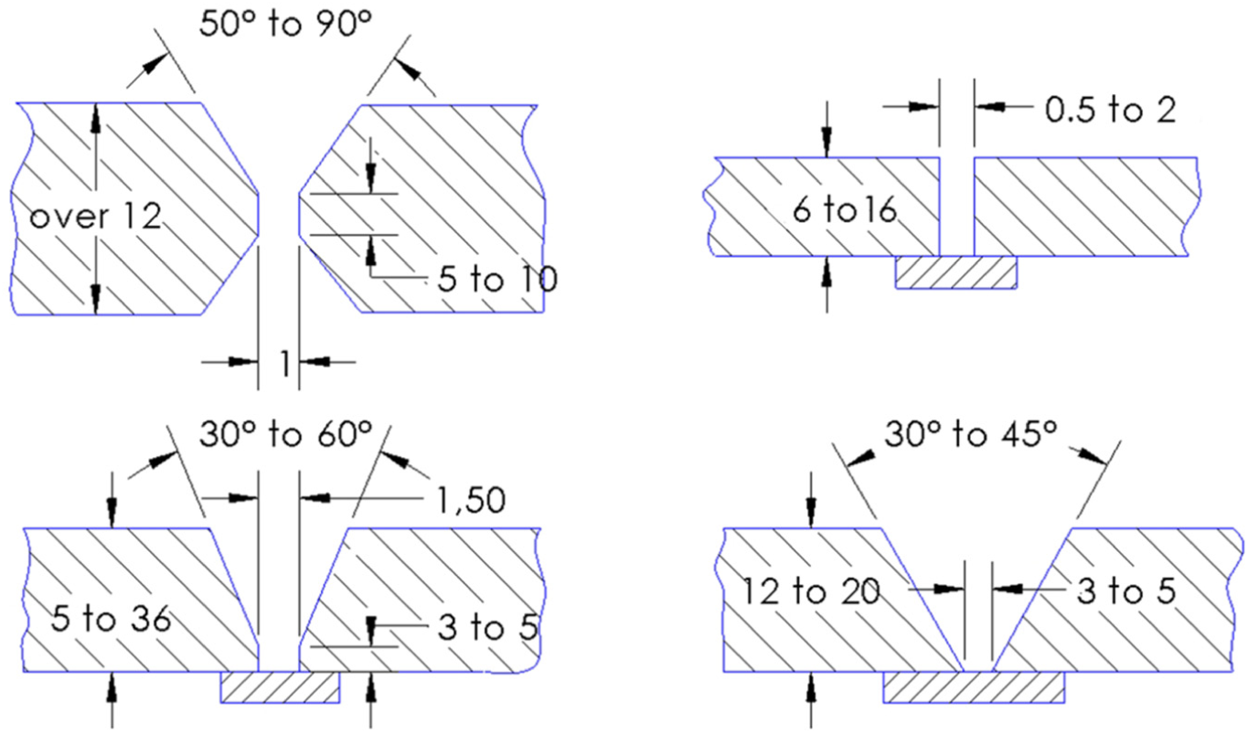
Several edge preparation cases are possible for NGW, and some are shown in Figure 2. Most common groove angle is 45°–55° with tight root opening. 36 V groove (Figure 2(a) and (e)) or U groove is recommended because no backing during welding is required. 30 However, to produce a radius on a groove, as shown in Figure 2(b) and (c), a milling or turning machine is required, and therefore, the size of the groove is restricted. Therefore, the optimum design is V groove (Figure 2(a) and (e)) with groove angle up to 10° or square groove (Figure 2(d)). Groove preparations shown in Figure 2(c) and (d) are used more often, as they can be manufactured by laser, plasma, or gas cutting, which are cheaper and easier than milling.
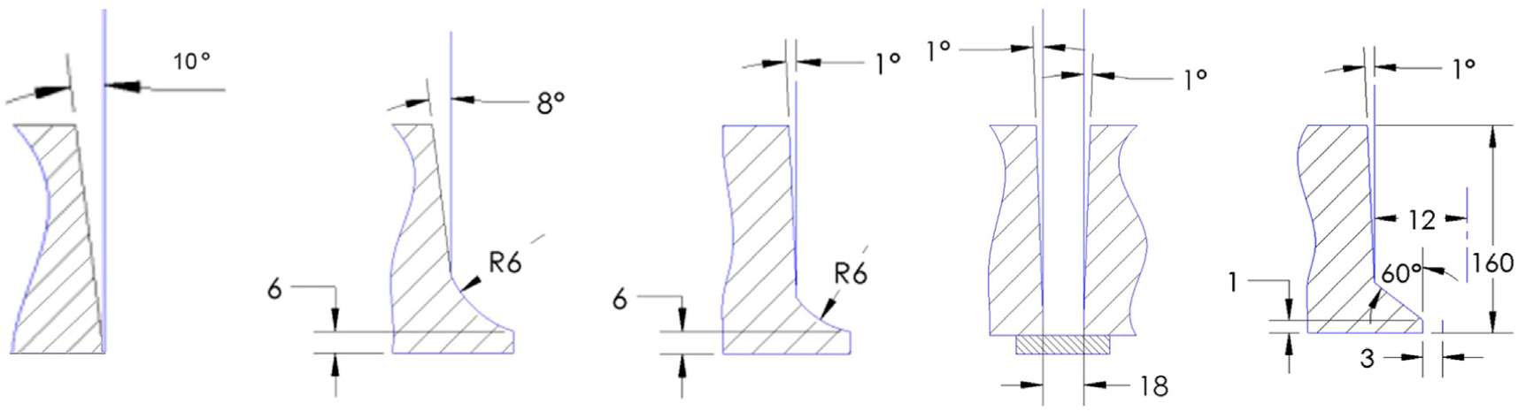
One of the main advantages of NGW is the reduced consumption of filler material compared to conventional weld groove preparation because the narrower the preparation, the smaller the welding metal consumption. For instance, when welding 100-mm plate, the weight of weld metal per unit length of a U joint reduces with taper from 8° to 1° and from 18.6 to 11.3 kg/m.
As the weld is made in a narrow slot, special provision must be made to avoid arc strikes between the welding head and the side walls. An adequate side wall fusion required precise alignment of the head to compensate for longitudinal drift of the rotating vessel. In the case of a circumferential joint of a pressure vessel rotating on rolls, some system of correcting axial drift must be employed. 35
Generally, NGW is carried out as a single pass per layer, and the gap is set sufficiently narrow so that both walls of the groove can be fused by the centrally positioned electrode, as it can be seen in Figure 3(a). In cases when there is more than one passes per layer, the grooves have a slight bevel angle of 1°–3° to allow for shrinkage and prevent jamming of the welding head.
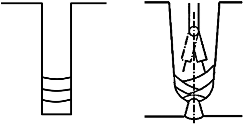
Different types of NGW: (a) arrangement of the groove for single pass per layer and (b) arrangement of the groove with an oscillating electrode. 37
For maximum welding efficiency, it is advised to use the narrowest possible groove and root gap. The single pass per layer technique shown in Figure 3(a) gives the shortest time for joint completion but lacks tolerance mainly because the single wire must be centrally aligned in the NG preparation to achieve constant fusion into both side walls. Compensation for irregularities in weld preparation can be achieved only by changing parameters such as travel speed, voltage, and current and not by manipulating the electrode wire. The narrower preparations used for single pass per layer welding can also exacerbate the need for slag removal. Experience suggests that for a single pass per layer, groove widths should be up to 18 mm or slightly greater, with a wire of 3.2 mm diameter. 37 Oscillating electrode method (Figure 3(b)) solves many problems of NGW, as it allows precise and uniform filling of the gap, thus avoiding welding defects.
Because of low heat input and multi-pass retempering, a fine-grained structure of the weld is achieved, as well as minimal distortion and residual stresses in the HAZ. Experimental comparison of residual stress in multi-pass NGW and conventional single U groove of butt-welded pipe showed that the values are almost identical. The smaller amount of weld metal also helps to decrease the residual stress that welding metal introduces in the weld joint. Nevertheless, slag removal between the welding phases and visual inspection after every welding pass may rise the cost of this welding process. 38
Weld quality of NGW is more sensitive to welding conditions than conventional welding methods. 35 Slag inclusion and lack of fusion in the side wall are the most common defects in NGW. In the case of multi-pass NGW, poor cleaning of the weld surface after each layer can result in entrapment of slag, even despite applying special NGW fluxes that facilitate slag removal. 35 Repair of defects is extremely difficult due to the small welded area; therefore, it is highly important to use accurate joint fit ups, trained operators, and special filler material with a suitable welding procedure and specification. 39 Therefore, the NGW method requires high accuracy of power supply characteristics and close tolerance for electrode tip to work distance as well as special and expensive filler metals and a special welding head.
Multi-wire SAW
The simplest form of SAW utilizes a single electrode and a direct current (DC) power source. More advanced twin-wire SAW uses two welding electrodes of with one power source and feeder system. The utilization of two wires results in an increase of deposition rates by up to 20% or more compared to single-wire DC SAW for the same level of heat input. 39 The higher deposition rate comes from the greater current density. Multi-wire welding delivers exceptional penetration and is capable of operating at high travel speed. Moreover, as in multi-wire welding, the energy loss to the environment is comparatively smaller than in single-wire welding, and it can be expected that in multi-wire welding, the energy efficiency will be higher. The mechanical properties of the weld are more favorable if the weld is made by multi-wire welding than by single-wire welding, because fewer microstructural transformations occur in the weld. 40
Direct current electrode negative (DCEN) SAW can provide about 30% gain in the deposition rate; however, the penetration is low; therefore, there is a chance of incomplete penetration welding defects. 39 SAW with alternating current (AC) is a compromise solution with higher deposition rate than positive-polarity welding but still larger penetration depth than welding with negative-polarity current. Square-wave AC output results in a more stable arc compared to the conventional AC characteristics. This fact is caused by the nature of the process, as the current changes faster from peak-positive current to peak-negative current.
One more modification for multi-wire SAW is tandem welding. Tandem welding is a process that utilizes two welding electrodes, each with separate power source and the wire feeding unit. Each welding electrode uses different current characteristics—the lead wire uses generally direct polarity and the trail welding electrode utilizes AC. Both wires feed into the same molten pool, allowing for deposition rates that are more than double what is achievable with single-wire SAW. One reason for choosing tandem over twin is the ability to control the wires individually and avoid issues such as arc blow. Arc blow can be prevented by connecting one of the electrodes to a direct current electrode positive (DCEP) source and the other to an AC or both to phase-shifted AC sources.
It is also possible to combine twin and tandem welding. Known as tandem–twin SAW, this process uses two sets of twin wires and a combination of DCEP/AC or AC/AC to achieve the highest possible deposition rate. The result can amount to a productivity gain of up to 40% compared with standard twin-wire welding. 32 The electrodes can be added as hot or cold. Hot wires are connected to a power source, and a cold wire is isolated until melted by the heat generated by the welding arc. Traditionally a cold electrode is brought in from the side into the weld pool and is used to increase the deposition rate by up to 40% while restraining heat input, which is especially important for Arctic steels. The following ways to use multiple electrodes have been developed: multi-wire welding, hot wire welding, and cold wire welding. 39 Some of these multi-wire SAW modifications are shown in Figure 4.
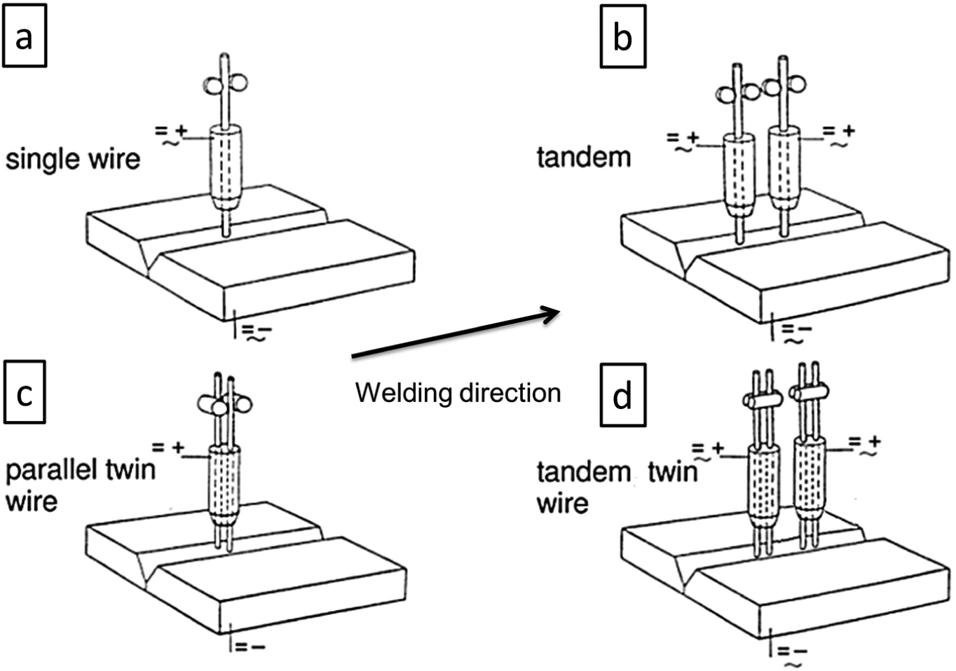
Various multi-wire SAW modifications: (a) single-wire welding, (b) tandem welding, (c) parallel twin wire, and (d) tandem–twin wire. 35
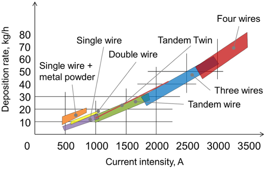
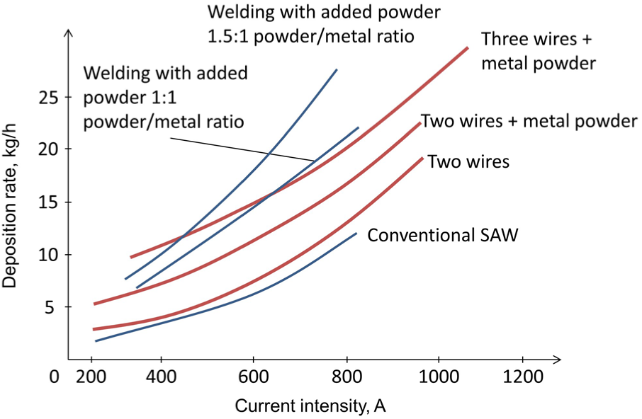
Obviously, different modifications result in different deposition rate values. Figure 5 compares and illustrates deposition rate over current for various modifications of SAW. As can be seen, the deposition rate increases at a very high rate when current rises. Additional welding electrodes also dramatically increase the deposition rate.
Multi-wire SAW allows the use of up to six wires together, being connected to six independent power sources. The first welding electrode is called the lead wire, and the last one is the trail wire. The lead wire is usually DCEP polarity with the trailing wires being AC.7,28,41,42
Each welding electrode in multi-wire welding process has a unique function, as it is shown in Figure 6. The leading electrode produces the optimum penetration by employing the higher welding current, and the following trailing wires fill the joint and are responsible for weld bead width and reinforcement height.5,43 Depending on the seam geometry, the last wire produces a broad seam with an excellent surface, usually at lower current and higher voltage. 34 A popular setup for longitudinal welds for pipes is three-wire welding with a single lead wire on DCEP for penetration, combined with two trail wires on AC for increased deposition rate. The use of two different current types, DCEP and AC, prevents interferences between the two welding arcs. As Figure 6 shows, the penetration is the largest for trailing electrode, reducing in vertical electrode and the smallest in leading electrode. The opposite situation is for the weld reinforcement height and for the tendency to undercut defect.
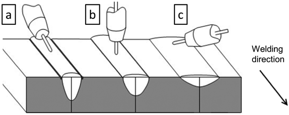
Effect of electrode angle on butt welds: (a) trailing electrode, (b) vertical electrode, and (c) leading electrode.
Multi-wire SAW can achieve speeds of up to 2.5 m/min, which is considerably higher than single-wire welding, giving a maximum deposition rate of 90 kg/h. This technique is particularly suitable for longitudinal pipe welding. Wire diameter can vary from 3 to 5 mm. Currents are typically from 2000 to 5500 A using both DCEP and AC. Voltage can reach 30–42 V per wire. Multi-wire SAW usually has three or four welding electrodes placed in the subsequent order toward the direction of welding. Normally, wires are arranged subsequently in the welding direction, although other types of arrangements are also possible. Parallel arrangement is mainly used for cladding. Research suggests that the electrode inclination angles should be put in the direction of the welding to reduce probability of welding defects, such as undercut and distortions of the weld shape. 44
Multi-pass welding always starts with the root pass. As Figure 7 shows, sometimes supporting plate might be used. The use of the supporting plate allows welding with higher energy input because the melted metal is kept inside the groove. Thick plates can be welded from both sides (Figure 7) by double V or U-butt groove. In this case, after the root pass is welded, one-side welding takes place, then plate is turned, and the root pass must be machined. 35
Multi-wire welding case study of welding X70 plate
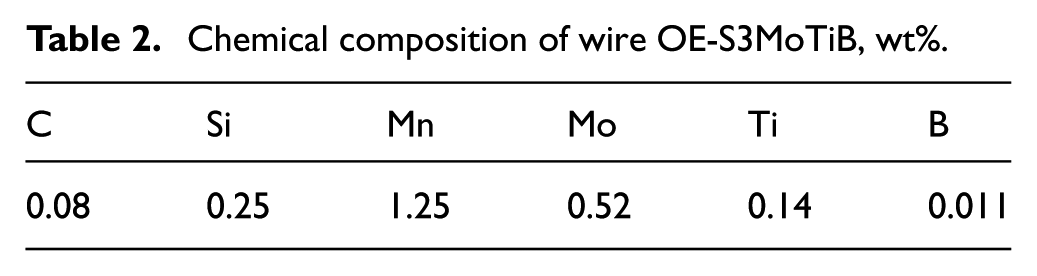
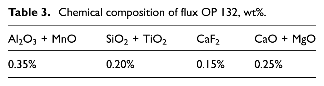
A case study on welding X70 steel plate was conducted. The experimental study features welding X70 Arctic grade steel by multi-wire SAW. Arctic steel plate X70 of 12.7 mm thickness was welded by multi-wire SAW with four electrodes. The wire grade was OE-S3MoTiB, and the flux was OP 132. Both the wire and the flux are optimized for multi-wire welding using two-run SAW technique for applications with high toughness requirements. The chemical composition of the wire and the flux is listed in Tables 2 and 3, respectively. The welding groove preparation is shown in Figure 8.
Chemical composition of wire OE-S3MoTiB, wt%.
Chemical composition of flux OP 132, wt%.
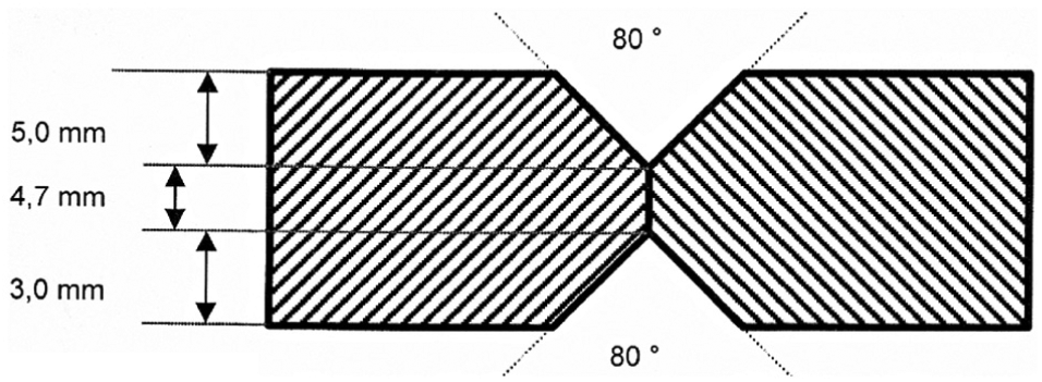
Weld seam preparation.
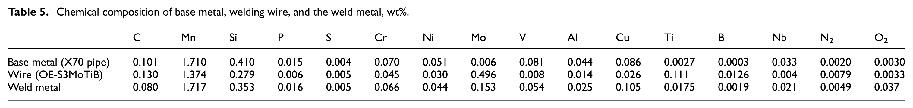
The welding procedure was performed by four wires on two sides of the plate. Welding electrode diameter is 4 mm, and other parameters such as current, voltage, and welding speeds are listed in Table 4. No preheat or postheat weld treatment was performed. The results of the chemical composition analysis of the base metal, welding electrode, and weld metal are presented in Table 5.
Welding parameters of the experiment.
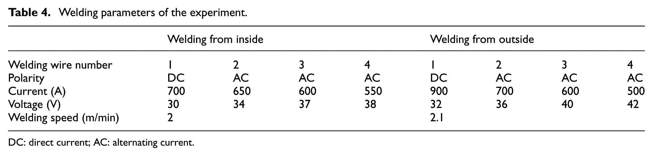
DC: direct current; AC: alternating current.
Chemical composition of base metal, welding wire, and the weld metal, wt%.
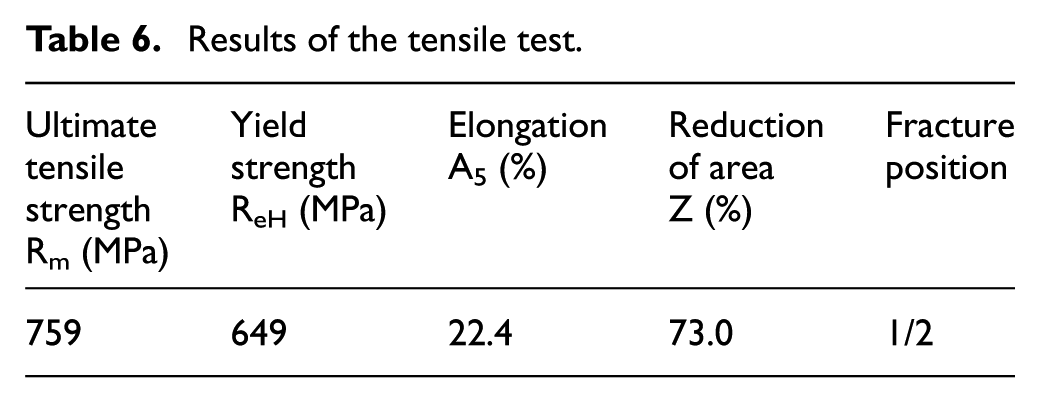
The welded steel was tested using criteria for Arctic use. Tensile test according to DIN EN 10002-1 is performed at room temperature. The specimen type Minitrac, of diameter 5 mm and length 25 mm, according to ISO 6892, was used for testing. The results of the tensile test are shown in Table 6.
Results of the tensile test.
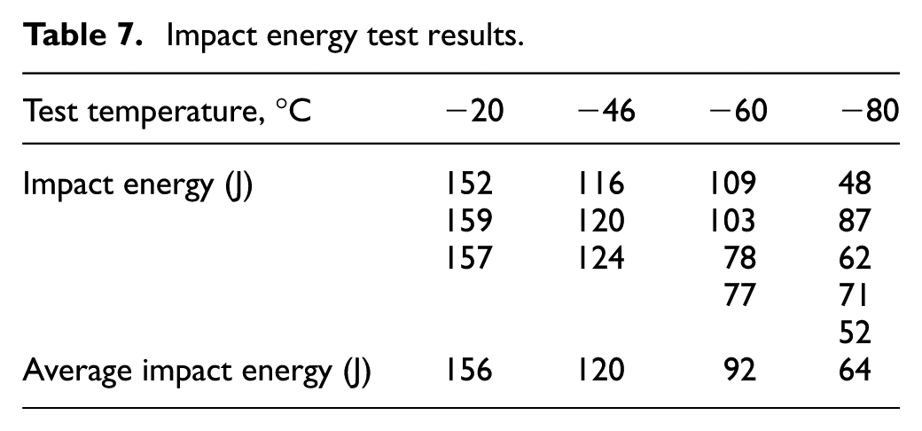
An impact strength test was done according to DIN EN 10045-1 (Charpy V). The specimen was made according to ISO 148-1:2009 standard, and notch position was T, according to DIN EN 875. The results of the test are given in Table 7. As can be seen, the welding procedure showed satisfactory results, and the welded steel is suitable for application in Arctic structures.
Impact energy test results.
Multi-wire welding case study of welding typical high-strength low-alloyed steel
In a study by Kiran et al., 5 single-pass tandem SAW was examined for welding high-strength low-alloyed (HSLA) steel. The experiment arrangements as well as welding parameters are shown in Figure 9 and Table 8.
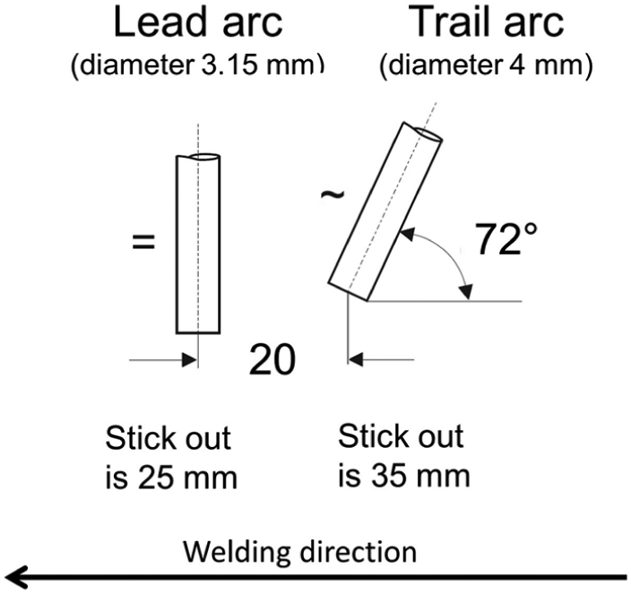
Tandem wire arrangement. All sizes are given in millimeter. 5
Welding parameters. 5
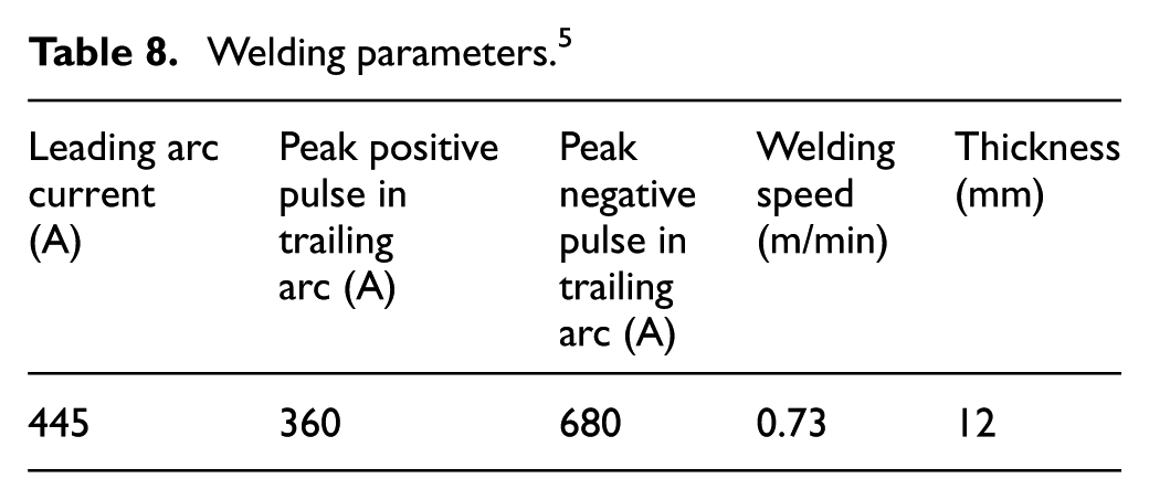
The experimental investigation demonstrates that the weld bead width and weld reinforcement height mostly depend on the trailing electrode current. The depth of penetration is mostly affected by the lead electrode current. Larger trailing wire current pulses enhance the size of the weld pool, which tends to slower the cooling time, inhibits AF phases in weld microstructure, and results in nonsatisfactory mechanical properties of the weld. Contrary, the increase in the speed of welding reduces the weld pool size, leading to higher cooling rate, which promotes a larger volume fraction of AF phase and, therefore, improved mechanical properties of the welding groove.
SAW with metal powder additions
In SAW with metal powder additions, the deposition rate can be considerably increased while maintaining constant current and voltage. Metal powder additions are used with the SAW process to decrease the arc energy needed to complete a joint. Utilization of metal powder addition can increase the deposition rate up to 100 kg/h. Using powder addition is an inexpensive way of significantly increasing the deposition rate. The gain in the deposition rate is realized by either the addition of a currentless wire (cold wire) or a preheated filler wire (hot wire). The use of a rectangular strip instead of a wire electrode delivers a higher current-carrying capacity and expands the application range of the SAW method to a wide range of surfacing applications. 35 Figure 10 illustrates various SAW modifications.
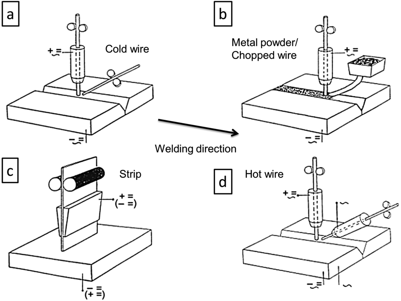
Various SAW modifications for increased of deposition rate: (a) cold wire welding modification, (b) metal powder or chopped wire welding modification, (c) strip welding modification, and (d) hot wire welding modification. 35
In SAW modifications using powder, typical chemical composition of the powder is 0.15% C, 0.40% Si, 1.7% Mn, 0.010% P, and 0.010% S. Typical grain size of the powder is from 0.071 to 0.75 mm, with a density of about 3 kg/dm3.
The powder can also be used to add certain elements to the weld to obtain special properties such as low-temperature resistance, improved AF formation, or better corrosion resistance. Research 46 has evaluated the effects of alloy additions of Ni, Mo, and Ni and Mo on the impact toughness of an HSLA API X70 steel welded by SAW. It was found that Ni additions contributed to low impact toughness and a raised fracture appearance transition temperature in the weld metal. The formation of AF should be attributed to the influence of Ni. The increase in Mo content created an AF-predominant weld metal microstructure with strongly improved toughness. 46 Therefore, the combined presence of Ni and Mo in the weld metal decreased the volume fractions of grain-boundary ferrite and promoted formation of high toughness of AF.
The influence of titanium powder additions on API 5L-X70 steel was studied in Beidokhti et al. 47 It was found that the best combination of microstructure and impact properties was obtained in the range of 0.02%–0.05% Ti in the weld metal. With further increased Ti content, the microstructure changed from a mixture of AF, grain-boundary ferrite, and Widmanstätten ferrite to a mixture of AF, grain-boundary ferrite, bainite, and ferrite with a martensite–austenite micro constituent. Accordingly, the fracture mode changed from dimpled ductile to quasi-cleavage. Titanium-based inclusions are beneficial for the impact toughness properties, as Ti contributes to the increase in AF formation in the microstructure. 47
The process scheme for SAW with metal powder additions is shown in Figure 11. As can be seen, there are two options for supplying metal powder to the weld (options a and b in Figure 11). The easiest way is to add the powder in front of the welding electrodes (option a). The powder is supplied to the weld and after that it is covered by the flux. A welding machine with metal powder addition to the welding groove area in front of the welding electrodes is provided in Figure 12(a).
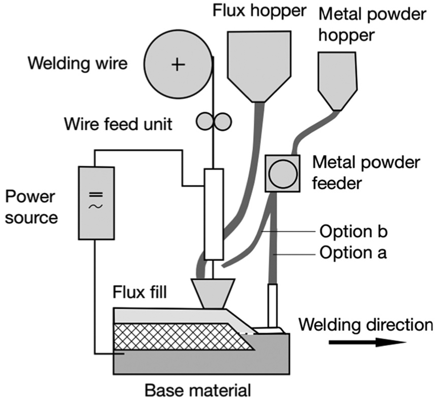
SAW process with the addition of metal powder. 27
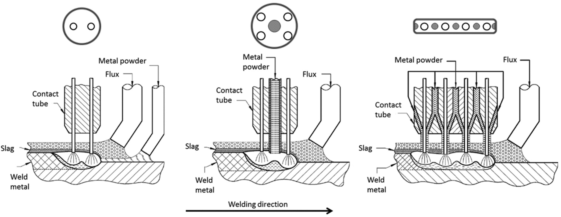
Various arrangements of metal powder supply: (a) welding system with two wires and metal powder added to the welding area, (b) welding system with four welding electrodes and metal powder additions, and (c) welding system with four welding electrodes and metal powder additions. 39
The option b shown in Figure 12 shows that it is also possible to supply metal powder via a pipe fixed between the welding electrodes. This technique is beneficial because the metal powder is added straight into the space between welding wires. The approach is especially applicable in case if both welding electrodes are placed successive. The reason is the first arc burns between the workpiece and the first welding electrode allowing deeper penetration. The arc of the second welding electrode melts the metal powder. Metal powder additions allow extremely high energy efficiency, keeping the use of shielding flux low. Possible metal powder delivery layouts are shown in Figure 13(a) and (b).
Metal deposition rates in SAW with metal powder addition. Electrode diameter is 3 mm. 45
Metal powder also can be used with a multi-wire SAW process. A welding system which combines several welding electrodes and the addition of the metal powder is shown in Figure 13(c).
This figure illustrates the twin-wire welding system with metal powder added to the welding zone parallel to the wires. The current moving inside the welding electrode creates the magnetic field, which in turn magnetize the metal powder to merge with the welding pool. After being attracted to the welding zone, metal powder melts and, therefore, additionally increases the deposition rate of the welding process. Welding equipment can include various amounts of welding electrodes, ranging from one to four or more, depending on the application requirements.
Figure 13 shows experimentally obtained values for the deposition rate as a function of current value per wire in multi-wire welding with a welding electrode diameter of 3 mm. 43 As can be seen from Figure 13, the deposition rate increases slightly more than exponentially with the increase in welding current and exponentially with each additional welding electrode. 39
One of the benefits of SAW with metal powder additions is a reduction in the shielding flux consumption. Figure 14 illustrates utilization of the flux depending on the welding current. The above-mentioned chart shows that less shielding flux is used if the metal powder is supplied to the welding area.39,43
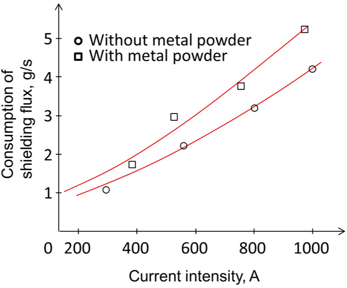
Use of shielding flux in SAW and SAW with the addition of metal powder depending on the electric current. Parameters of the experiments were U = 25 V, Vw = 0.9 m/min, and welding electrode diameter is 3 mm. 43
Utilizing metal powder addition permits the attainment of a high rate of weld deposition and more economical use of filler material. However, this modification still has all the disadvantages of SAW, namely, difficult arc starting, the possibility to weld only in flat positions, and limitations for materials to be welded. Aluminum alloys, magnesium alloys, and titanium cannot be welded because of the nonavailability of the flux. SAW with metal powder additions is currently used mainly for heavy steel plate fabrication in shipbuilding. 48
Discussion
This article focuses on various modifications of SAW, such as NGW, multi-wire SAW, and SAW with metal powder addition. A summary and comparison of key features of these processes is given in Table 9.
Comparison and summary of SAW processes.
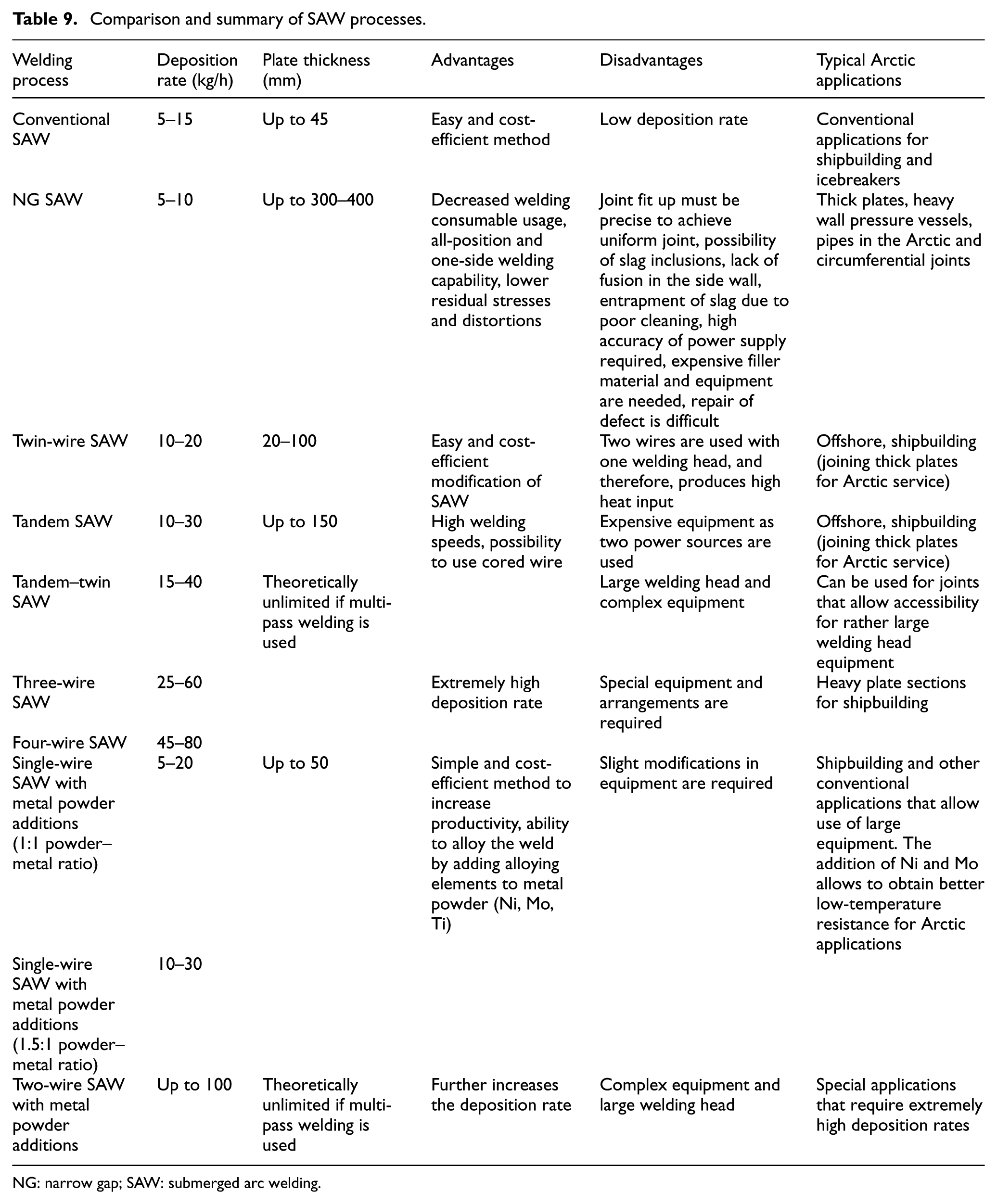
NG: narrow gap; SAW: submerged arc welding.
NG SAW has various economic benefits, for example, reduced demand for filler material and higher welding speed, whereas technical advantages are less shrinkage, lower distortion, and reduced residual stresses due to fewer passes. Most common applications of NG SAW are for materials particularly sensitive to heat input, including HSLA steels, stainless steels, aluminum, and titanium alloys. These materials are most often used for construction of large structures (such as Arctic offshore structures) and components, such as shells, drums, steam pipes, pressure vessels, power plant components, and penstocks. Clearly, the reduced groove area allows cost reduction; however, too narrow groove might cause insufficient penetration.
Multi-wire SAW is capable of delivering extremely high deposition rates, as well as filling wide joints. There are several possible arrangements of wires to adjust the process to a particular application. Multi-wire SAW usually utilizes 2–4 electrodes, each playing a unique role in the weld formation. Typical materials that can be welded using multi-wire SAW are thick sections made of non- and low-alloyed steels, including HSLA steels and HSS. The Arctic applications usually demand the use of thick plates; therefore, the multi-wire SAW is highly suitable. Increasing number of welding wires is one of the easiest steps to increase productivity. Generally, melt in rate of twin SAW is increasing up to 30%; nevertheless, the problem of achieving the required penetration depth can arise. The case study carried out for this article demonstrates the application of recommended parameters and shows multi-wire SAW example of welding 12.7 mm X70 Arctic grade steel plate with four wires.
SAW with metal powder addition is used to reduce the arc energy needed to complete a joint. Utilization of metal powder is a simple and cost-efficient way to significantly increase the deposition rate. Powder can be used to add certain elements to the weld in order to obtain special properties. Nevertheless, this modification still exhibits the most typical disadvantages of SAW, namely, difficult arc starting, the possibility to weld only in flat positions, and limitations on materials that can be welded. Aluminum alloys, magnesium alloys and titanium cannot be welded because of nonavailability of the flux. SAW with metal powder additions is used mainly for heavy steel plate fabrication in shipbuilding, such as icebreakers.
Conclusion
Materials for Arctic use should satisfy strict requirements imposed by the relevant standards, such as Charpy V notch test and CTOD test. The most critical part of the structure which usually fails these tests is the HAZ. Therefore, it is highly important to select correct welding process and parameters to prevent such failure. One of the most important welding process parameters which influences the low-temperature steel properties is the heat input. The special attention should be paid to limit the heat input during welding. Development of the Arctic industry will require welding large amount of thick HSS, and welding of HSS plates becomes especially challenging in light of the trend to increase tensile strength as a way to decrease the weight and cost of structures. Therefore, it is important to use high deposition welding processes to shorten manufacturing time and expenses. One of the most used welding processes in shipbuilding in offshore structure production is SAW. This article described and compared various SAW high deposition modifications such as NG SAW, multi-wire SAW, and SAW with metal powder additions.
This article included discussion of two case studies on multi-wire SAW of Arctic steels. The experiments for the first case study were carried out for the current research paper, and it was an experiment of welding X70 12.7-mm steel plate with a four-electrode welding technique. The obtained weld was tested by impact and tensile tests and showed acceptable values. The second case study described tandem welding of HSLA steel for Arctic service. The experiment covered welding parameters that were used to achieve a successful result.
It is concluded that for successful operations in the Arctic area, advanced welding technologies should be used. The quality and productivity of the weld joints produced by the advanced welding processes and methods examined allow efficient production of desired weld joints fulfilling the properties required for Arctic conditions.
Footnotes
Declaration of conflicting interests
The author(s) declared no potential conflicts of interest with respect to the research, authorship, and/or publication of this article.
Funding
The author(s) disclosed receipt of the following financial support for the research, authorship, and/or publication of this article: This research was carried out in the Welding Technology Laboratory of Lappeenranta University of Technology (LUT) and was supported by the Finnish Funding Agency for Technology and Innovation (TEKES) as a part of TutLi-project: “Neural-Network-Controlled Self Regulating Welding System”. Additionally, part of the work has been done within the framework of the partnership agreement “Development of materials and technologies for the Arctic” as from February 1, 2012 with Lappeenranta University of Technology.