
Abstract
In order to achieve the high-quality roller mold used in roll-to-roll fabrication of optical prism films, this article investigates the effects of cutting parameters on surface quality during diamond turning of micro-prism array, and some cutting experiments are carried out on home-made ultra-precision drum roll lathe. The surface defects such as micro pits and burrs are presented and discussed at different cutting parameters. The experimental results show that, when the cutting depth is more than 4 µm, the plowing force becomes the dominant factor to remove material, which may cause the generation of micro pits on the side surface of micro prism. During multiple-step diamond turning of micro-prism array, the final cutting depth is recommended not to exceed 2 µm; in this case, there is no generation of micro pits and the height of burr is less than 13.6 nm. Moreover, the well-controlled cooling and chip evacuation can effectively improve the influence of cutting speed on surface quality. Finally, micro-prism array with pitch of 40 µm is successfully machined without apparent surface defects.
Introduction
The past decades have witnessed the rapid development of liquid crystal display (LCD) panel industry, which have been widely used in the fields of TV, laptops, mobile phones, and public information display.1,2 The brightness enhancement film is a critical functional component of the LCD and its surface is uniformly covered with micro-prism array, which can improve the light transmittance and increase the brightness and viewing angle. 3 Roll-to-roll (RTR) process is a high-efficiency and high-precision processing method to fabricate the large-scale microstructured surfaces such as micro-prism array.4,5 The precision manufacturing of the roller mold with microstructured surfaces is the key technology in RTR fabrication process. 6 Ultra-precision diamond turning is considered as a deterministic nanoscale machining process using ultra-sharp single-crystal diamond tools, 7 and it has been recognized as the best option in roller mold manufacturing because the diamond tool possesses the super hardness and high resistance to wear, and the high-quality optical surface and sub-micron form accuracy can be achieved on nonferrous materials.8,9
Early efforts of many researchers have laid a good foundation for diamond turning of microstructured surfaces to the current stage. Brinksmeier et al. 10 have developed a nano fast tool servo (nFTS)-assisted diamond turning process to machine microstructures with nanometer precision, which could improve the surface quality of diffractive optical elements. Gao et al. 11 have achieved the fabrication of a large area sinusoidal grid surface with spatial wavelengths of 100 µm and amplitudes of 100 nm. In order to avoid the light interference phenomenon and enhance the optical efficiency, Je et al. 12 have machined the micro complex prism patterns on a copper-electroplated roll master, and various pitches and heights of prism array were accomplished. Le et al. 13 have established the prediction model of burr formation in micro-grooving, including the side burr of micro-prism pattern and exit burr of micro pyramid pattern. However, this prediction model of the side burr in grooving micro-prism pattern is not suitable for the case of the tool nose angle greater than 90°, because the calculated burr height is negative. The severe burr and dimensional error of micro-prism pattern caused by tool wear will degrade the light uniformity and efficiency of backlight unit (BLU). Park et al. 14 have carried out the experimental study of wear characteristics of V-shaped diamond tool for micro-prism pattern, and the results showed that the surface roughness and the amount of burr were low when machining the Al alloys with high hardness. Fang and Liu 15 have demonstrated that the burrs were almost impossible to eliminate, even though they could be minimized to less than 25 nm in height in micro cutting. Keong et al. 16 have developed a layered tool trajectory method to extend the stroke in the FTS diamond turning of noncircular microstructural surfaces. Duong et al. 17 have presented a theoretical model for predicting the optimum cutting conditions for microchannels in ultra-precision diamond turning, but this theoretical model did not take into account the effect of tool wear and chatter. During diamond turning, the cutting force, normally at the 0.1–1 N scale, is closely related to chip formation, surface generation and tool wear. Sawangsri and Cheng 18 have proposed a cutting force modeling for diamond cutting based on the amplitude and spatial aspects of cutting force formulation. Li et al. 19 have investigated the burr formation mechanism for micro cutting of V-shaped cylindrical grating template for roller nanoimprint. They attributed the burr uneven phenomenon to the metallographic inhomogeneous properties of the H62 Copper when machining the smaller pitch grating. Zhang et al. 20 have accomplished the ultra-precision diamond machining of the roller mold patterned with linear Fresnel lenses for solar concentration.
Surface defects such as micro pits and burrs may reduce the energy efficiency of the light source and result in the non-uniform brightness on display. Even though many researchers favored the ultra-precision diamond turning of microstructured surface, the studies on the relation between the generation of microstructured surface defects and cutting parameters are relatively scarce. In order to achieve the high-quality roller mold used in RTR fabrication of optical prism films, this article presents an experimental study on the effects of cutting parameters on surface quality during diamond turning of micro-prism array. A four-axis ultra-precision drum roll lathe is developed, and the surface defects such as micro pits and burrs are presented and discussed at different cutting parameters.
Experiments
Experimental setup
As shown in Figure 1, the copper-plated roll workpiece and flat workpiece are mounted on home-made ultra-precision drum roll lathe, respectively. The digital microscope is used for tool setting. Due to the excessive dimension and weight of the roll workpiece for the current measuring instruments, it is very difficult to directly measure the surface of roll workpiece. In addition, the replicated patterns cannot fully reflect the surface defects of micro-prism array, such as micro pits and burrs. Therefore, the following experiments will be carried out on the copper-plated flat workpiece in order to facilitate the measurement. Figure 2 shows the scanning electron microscope (SEM) photograph of V-shaped diamond tool with a tool nose angle of 90°, rake angle of 0° and relief angle of 7°. In addition, the experimental parameters are listed in Table 1.
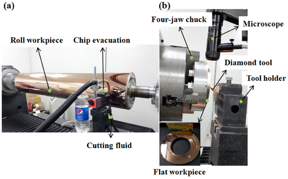
Experimental setup: (a) copper-plated roll workpiece and (b) copper-plated flat workpiece.
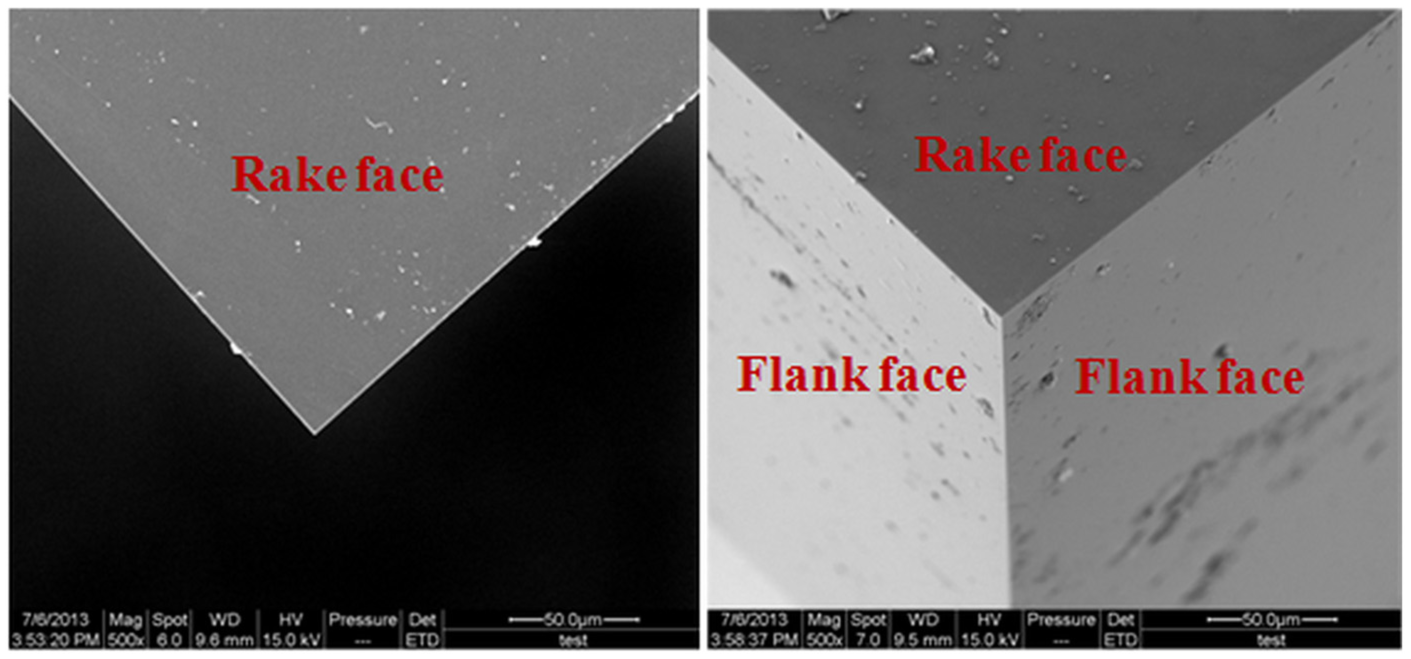
SEM photographs of V-shaped diamond tool.
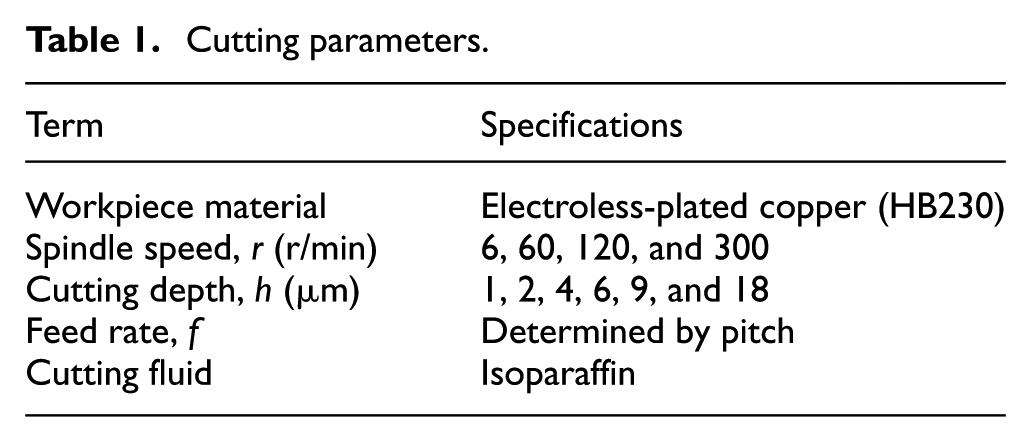
Cutting parameters.
Multi-step cutting method
Figure 3 shows the process of multi-step cutting method. The experiments use a thread cutting mode; hence, the designed pitch of micro-prism array is related to the cutting depth and feed rate. The black areas are the undeformed chip thickness areas of micro-prism array.
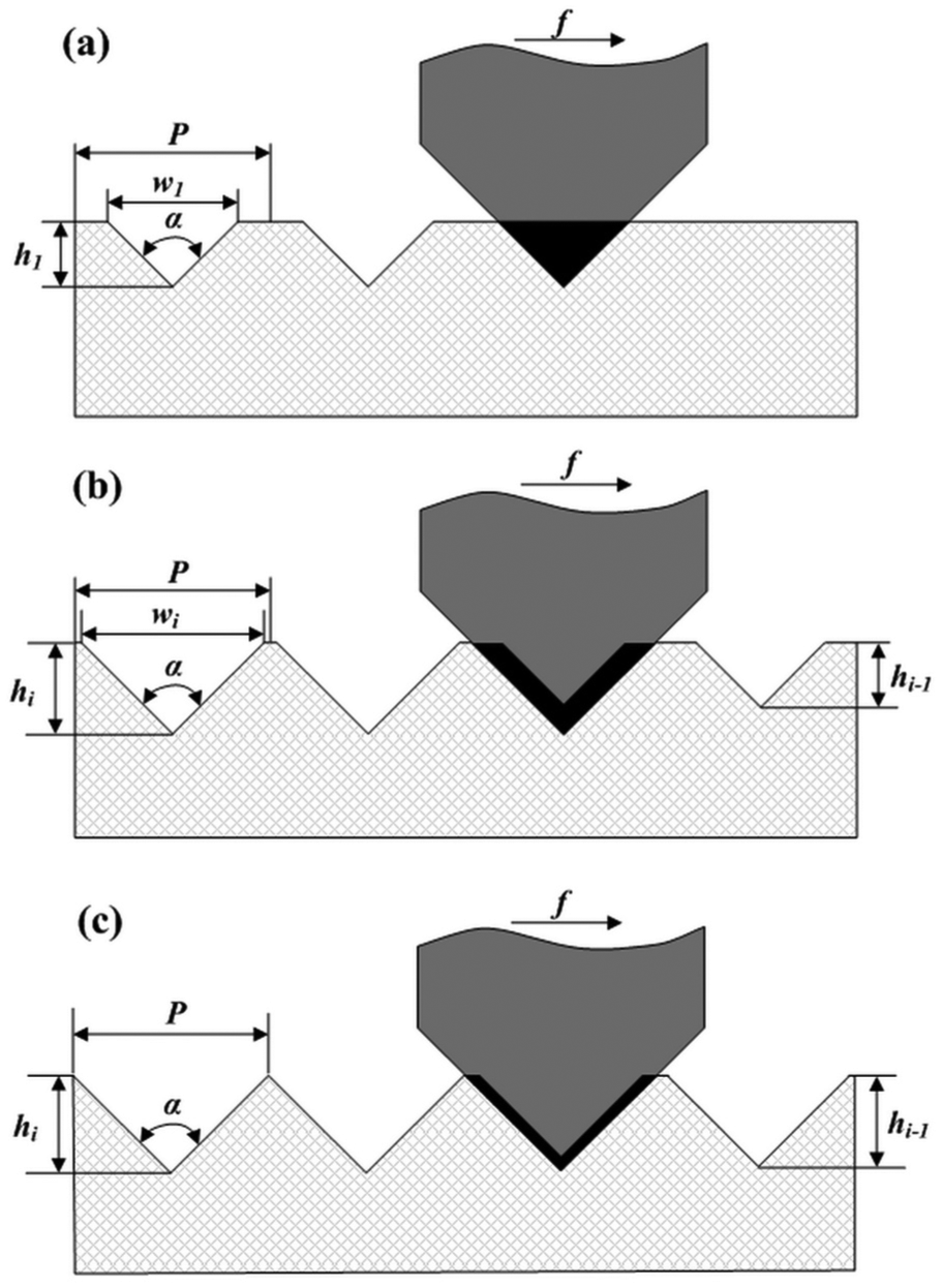
Multi-step cutting method of micro-prism array: (a) the first step cutting, (b) the ith cutting step when the cutting width w is smaller than the pitch, and (c) the final cutting step when the cutting width w is equal to the pitch.
For the first step cutting as shown in Figure 3(a), the undeformed chip thickness area is calculated by as follows
For the ith step cutting as shown in Figure 3(b) or (c), the undeformed chip thickness area is derived as follows
or
where P is the pitch of micro-prism array, α is the tool nose angle, w1 and wi are the cutting width of the first and ith cutting step, h1, hi−1, and hi are cutting depth of the first, (i − 1)th, and ith cutting step, respectively. Equation (2) is suitable for the case if the cutting width is smaller than the pitch, while equation (3) is suitable for the final cutting step. In this case, the cutting width is equal to the pitch.
Results and discussion
Surface defects such as micro pits and burrs of micro-prism array may degrade the optical performance. In RTR fabrication process, if there are some surface defects on the microstructured roller mold, these defects will be continuously replicated to the optical film productions. Therefore, it is necessary to analyze and discuss the effect of cutting parameters on surface quality of micro-prism array.
Effect of cutting depth
In this section, the article will discuss the effect of cutting depth in one-step micro-grooving. The cutting depth is 1, 2, 4, 6, 9, and 18 µm, and the spindle speed is 300 r/min. Since this experiment uses a thread cutting mode, the feed rate is determined by the designed pitch of micro-prism array. The SEM photographs of micro-prism array are shown in Figure 4 at different cutting depth. As it can be seen from Figure 4(a) and (b), when the cutting depth is smaller than 2 µm, the side surfaces of micro prisms have a good quality. While if the cutting depth is 4 and 6 µm as shown in Figure 4(c) and (d), there appears to be some micro pits on side surfaces of micro prisms. By comparison, the micro pits become very apparent and severe which almost cover the entire machined surfaces when the cutting depth is 9 and 18 µm as shown in Figure 4(e) and (f). Le et al. 13 have pointed out that there existed a critical thickness in which the normal cutting is impossible in micro-grooving. Above the critical thickness area, the material will be removed plastically along the feed direction. The equation of the critical thickness in micro-grooving has been presented as follows 13
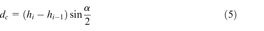
where tcr is critical thickness; dc is undeformed chip thickness; φ is shear angle; τs and σs are normal and shear stresses, respectively; and κ is the value of plasticity. From Figure 3, dc can be calculated
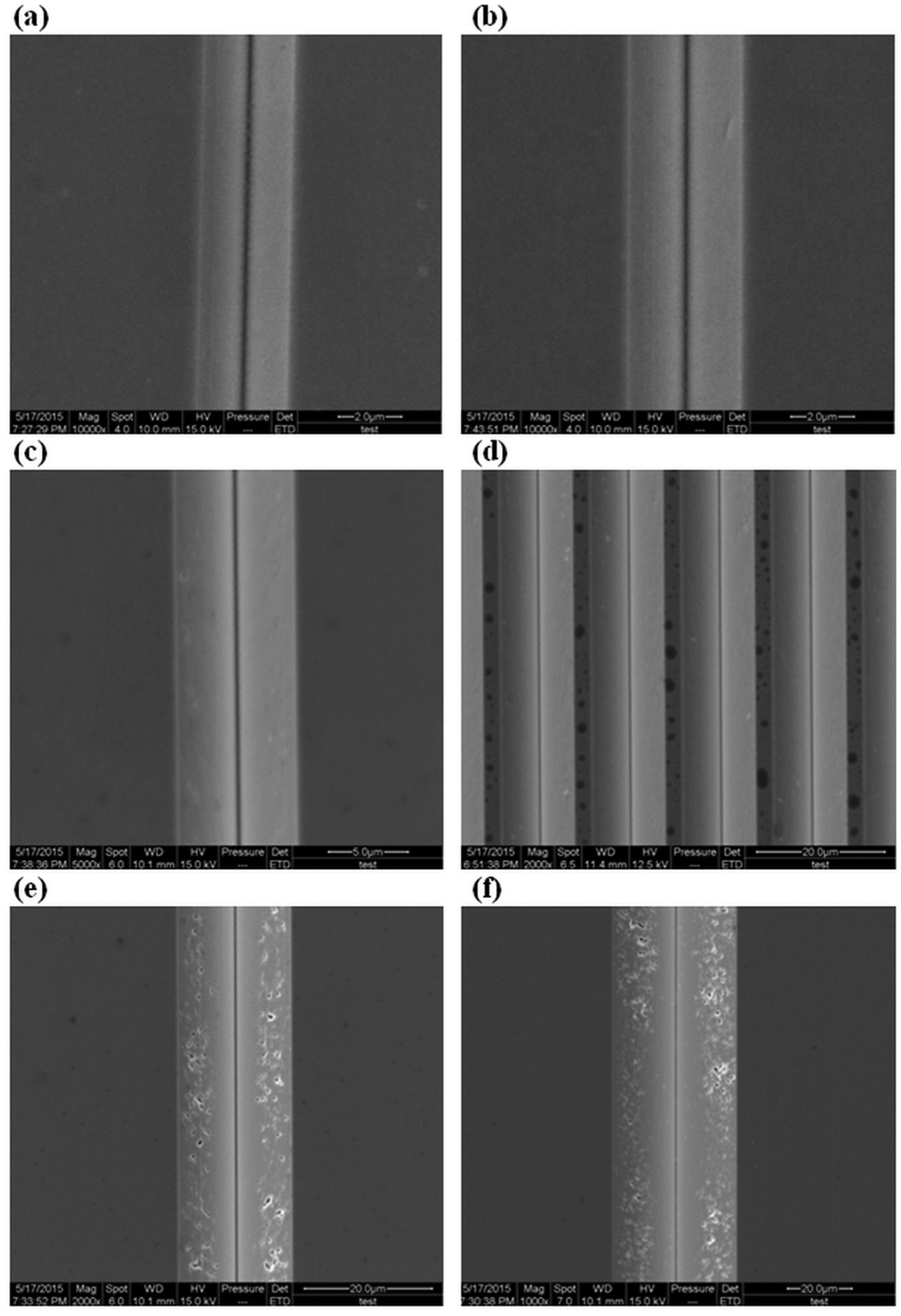
SEM photographs of micro-prism array at different cutting depth: (a) h = 1 µm, (b) h = 2 µm, (c) h = 4 µm, (d) h = 6 µm, (e) h = 9 µm, and (f) h = 18 µm.
As can be seen from the above analysis, when increasing the cutting depth, the critical thickness will increase accordingly. At the top surface of the critical thickness area, the plowing force becomes the dominant factor to remove material, which may deteriorate the surface quality and cause the generation of micro pits on the side surface of micro prism. The height of burr is measured by stylus profilometer (Form Talysurf, Taylor Hobson) as shown in Figure 5. It can be seen that some side burr is generated on the top of micro prism. With the increasing cutting depth, the height of burr increases as shown in Figure 6. The formation of side burr is mainly caused by side flow of material due to its ability of plastic deformation in the cutting region. The large height of burr severely reduces the light efficiency in BLU. Hence, the cutting depth should be controlled below 10 µm in micro-grooving; in this case, the height of burr is less than 20 nm.
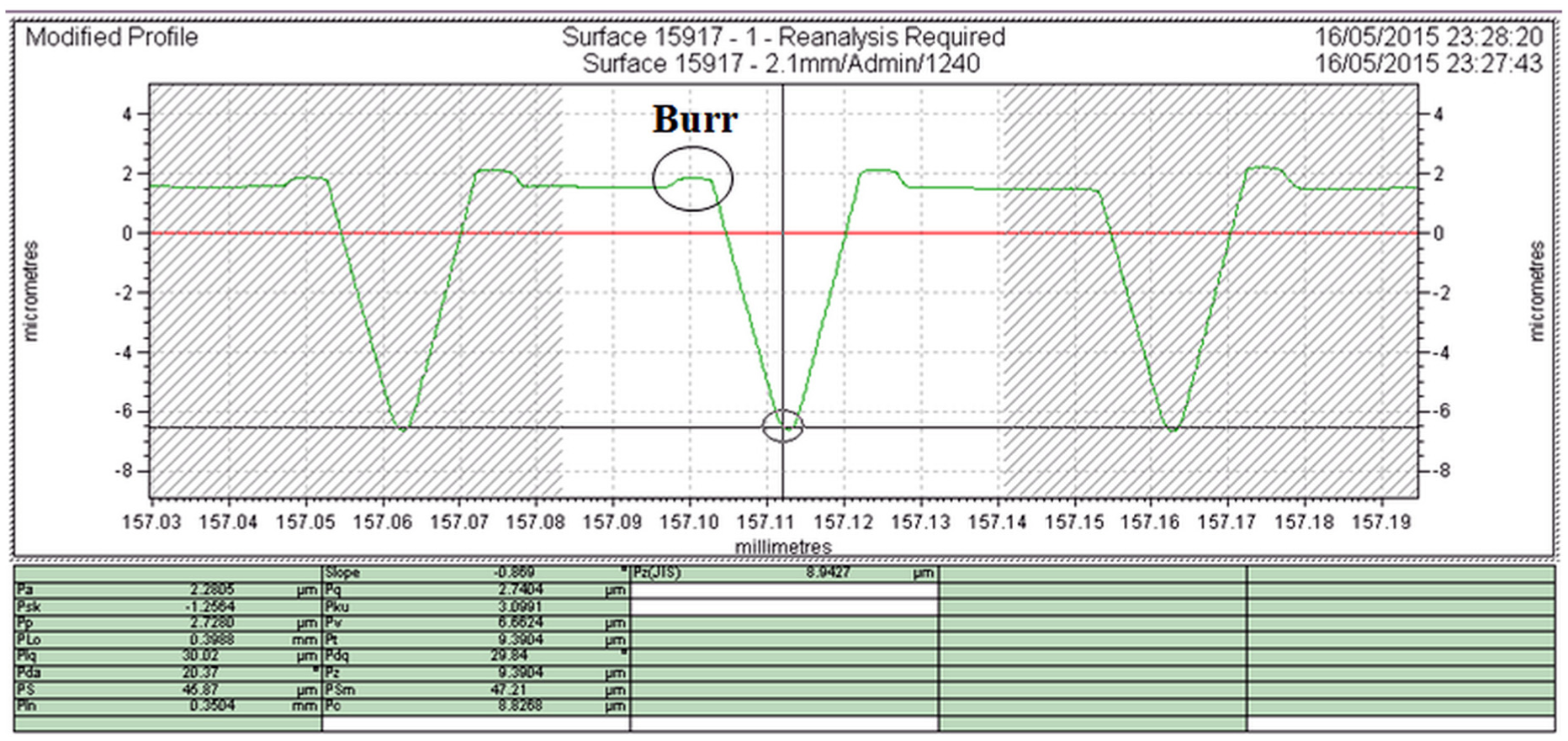
Measurement of height of burr.
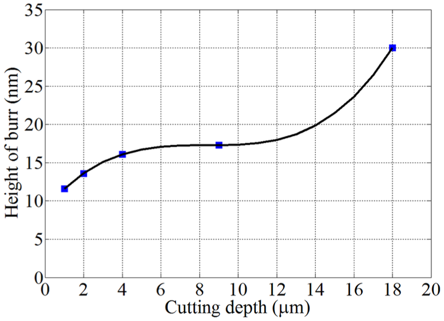
Height of burr at different cutting depth.
Effect of spindle speed
During diamond turning of micro-prism array, the spindle speed determines the actual cutting speed. At low cutting speed, it is more likely to generate built-up edge which will deteriorate the surface quality. However, relatively high cutting speed will affect the dynamic characteristics of the machine tool spindle. In order to study the effect of the cutting speed on surface quality, some cutting experiments are carried out at different spindle speed when the cutting depth is 2 µm. It can be seen that from Figure 7, the cutting speed has a small effect on the generation of micro pits on the side surface of micro prisms. Even though the spindle speed is down to 6 r/min, there are no apparent micro pits or burrs.
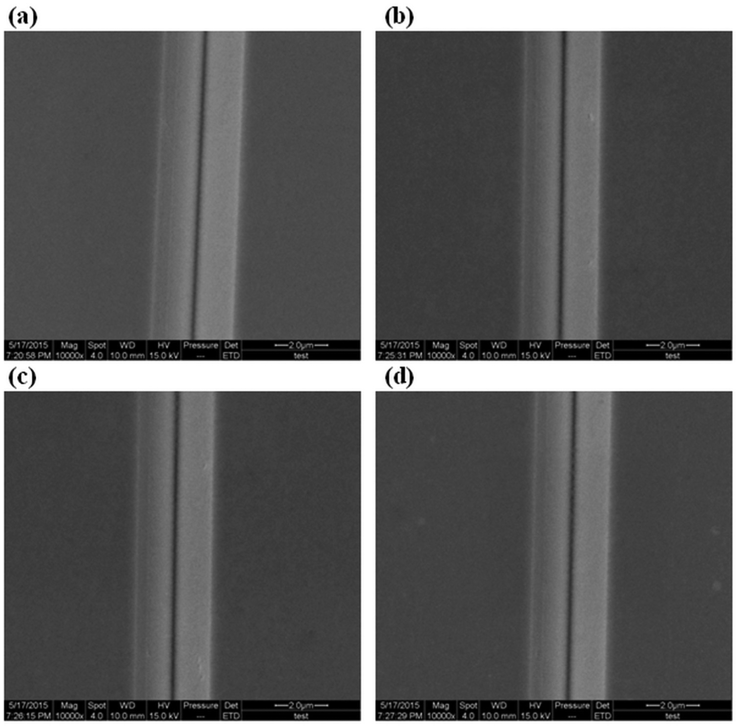
SEM photographs of micro-prism array at different spindle speed: (a) r = 6 r/min, (b) r = 60 r/min, (c) r = 120 r/min, and (d) r = 300 r/min.
The height of burr is shown in Figure 8, which presents that the spindle speed slightly affects the height of burr which is less than 8.5 nm even at different spindle speed. On one hand, this is because the workpiece material of electroless-plated copper (HB230) has a relatively high hardness and small plasticity. On the other hand, the well-controlled cooling and chip evacuation can effectively improve the influence of cutting speed on surface quality. Taking into account the machining efficiency, the spindle speed of 300 r/min is recommended in micro-grooving. According to the above-experimental results, two-step cutting experiment is carried out. The first and second cutting depth is 18 and 2 µm, and the spindle speed is 300 r/min. Micro-prism array with pitch of 40 µm is achieved as shown in Figure 9. There is a good consistency for micro-prism array, and no apparent micro pits or burrs are generated. In addition, the experimental results also prove that this home-made ultra-precision drum roll lathe offers a high repetitive positioning accuracy, which is significant for multi-step cutting of micro-prism array.
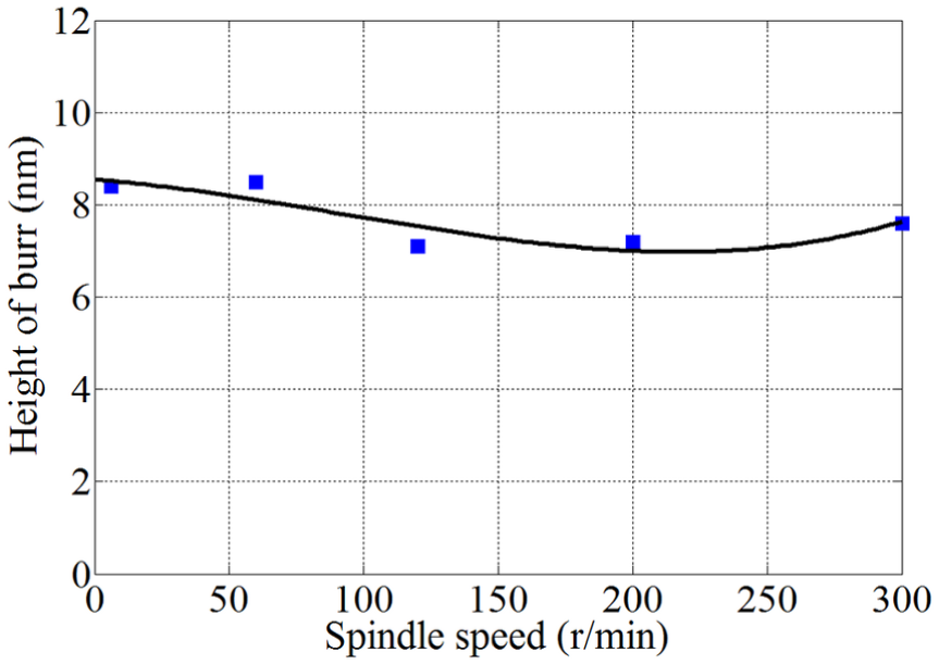
Height of burr at different spindle speed.
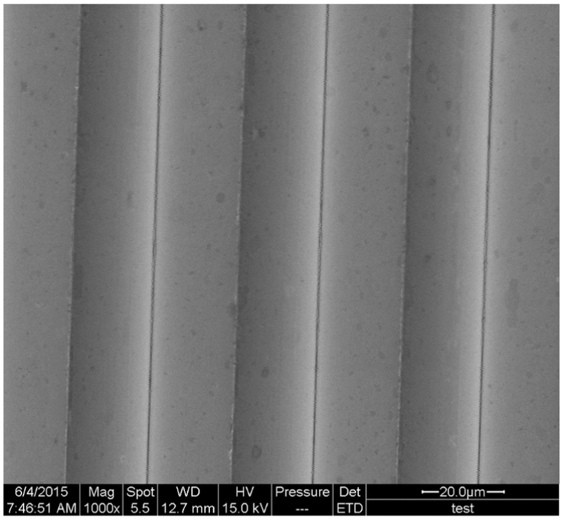
SEM photograph of micro-prism array with pitch of 40 µm.
Conclusion
This article investigates the effect of cutting depth and spindle speed on surface quality during diamond turning of micro-prism array, and some cutting experiments are carried out on home-made ultra-precision drum roll lathe. The surface defects such as micro pits and burrs are presented and discussed at different cutting parameters. Micro-prism array with pitch of 40 µm is successfully machined using two-step cutting method. Based on the results of experimental studies, the conclusion can be drawn as follows:
When the cutting depth is more than 4 µm, the plowing force will become the dominant factor to remove material, which may cause the generation of micro pits on the side surface of micro prism.
When increasing the cutting depth, the side flow of workpiece material due to its elastic and plastic deformations in the cutting region will enlarge the height of burr.
The final cutting depth is recommended not to exceed 2 µm during multiple-step diamond turning of micro-prism array. In this case, there is no apparent generation of micro pits and the height of burr is less than 13.6 nm.
Spindle speed slightly affects the generation of micro pits and height of burrs. The well-controlled cooling and chip evacuation can effectively improve the influence of cutting speed on surface quality.
Footnotes
Declaration of Conflicting Interests
The author(s) declared no potential conflicts of interest with respect to the research, authorship, and/or publication of this article.
Funding
The author(s) disclosed receipt of the following financial support for the research, authorship, and/or publication of this article: The research is supported by the National Science and Technology Major Project of High-end CNC Machine Tools and Basic Manufacturing Equipment of China (grant number 2011ZX04004–021).