
Abstract
Pressure-assisted forming of tubes allows producing a wide variety of tubular components that are difficult or impossible to fabricate by means of conventional tube forming. In contrast to previous investigations in the field that were almost exclusively focused on the utilization of fluids (tube hydroforming) or elastomers (tube rubber forming) as pressuring medium, the subject matter of this article is centred in the utilization of low melting point, recyclable, metallic alloys as solid pressurizing medium. The aims and scope of the article are centred on the feasibility of forming straight carbon steel tubes into complex gooseneck geometries with non-concentric cross sections using lead as a solid pressuring medium and employing a double-action cam-driven tool system. The presentation is focused on the tool system, on its adequacy to produce customized tubular components, on the required forming forces and on the typical modes of deformation that result from the different movements provided by the vertical and horizontal actuators of the double-action tool system. Results and observations confirm that the utilization of a double-action tool system with a solid pressurizing medium to assist plastic deformation and prevent collapse can be successfully and effectively employed to fabricate non-concentric tubular cross sections for prototypes and small batches of lightweight components.
Introduction
Cold forming of tubes with simultaneous action of external mechanical load and internal pressure established as an alternative to conventional manufacturing processes based on stamping, welding and casting in the late 1960s and 1970s. The pioneer investigations by Ogura and Ueda 1 and Al-Qureshi 2 showed that both fluids and elastomers could be successfully utilized as pressurizing medium in place of a hard tool to plastically deform a straight tube into a tee branch tubular component.
From 1960s to nowadays, the utilization of pressurized fluids evolved into tube hydroforming (THF), which is a technology widely utilized to produce large batches of tubular components with rotationally symmetrical (Figure 1(a)), rotationally unsymmetrical (Figure 1(b)) and eccentric (or gooseneck; Figure 1(c)) cross sections for automotive, household appliances and lightweight structures. 3
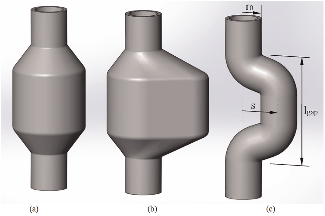
Classification of tube hydroforming as a function of the position of the cross section of the plastically deformed regions to the longitudinal axis of the original straight tube: (a) rotationally symmetrical, (b) rotationally unsymmetrical and (c) eccentric (or gooseneck) cross sections.
The main scientific and technological developments in THF are comprehensively described in the state-of-the-art review performed by Ngaile 4 who identified the main process parameters as the tubular material, the starting geometry (thickness and length), the desired shape and the loading path, namely, the combination of internal pressure and the external axial feeding that is needed to ensure large deformations without failure.
A recent publication by Lee et al. 5 extended the general principles and processes that were covered in the above-mentioned publication with recent technological developments and presented new modelling and design strategies for improving formability in THF. The development of pulsed THF, 6 the understanding of the mechanisms behind the improvement of formability in THF, 7 the utilization of advanced high-strength steels and magnesium alloys, and the utilization of new design and modelling strategies for achieving larger expansion ratios 8 and estimating the uncertainties in corner die filling 9 are some examples of the recent advances in THF.
Still, the main drawbacks of THF are the large cycle time, the capital investment in machines and tools (inhibiting small batch production), the safety precautions associated with the use of fluids subjected to very high pressures and the design guidelines that prevent the specification of tight bends with very sharp corners.
Similar to THF, the utilization of elastomers as solid pressurizing mediums evolved from 1960s to nowadays into tube rubber forming (TRF), which is an effective and widespread technology to produce small batches of tubular components with rotationally symmetric (Figure 1(a)) and rotationally unsymmetrical (Figure 1(b)) cross sections containing simple counterdrafts and local expansions.
The main scientific and technological developments in TRF are described in the state-of-the-art review performed by Thiruvarudchelvan 10 and covered in a comprehensively and broader range in the book recently published by Ramezani and Ripin. 11 The main advantages of TRF compared to THF are the elimination of the need to use robust hydraulic presses with plenty of daylight for installing the die sets, the elimination of the difficulties that arise from sealing fluids subjected to very high pressures and the aforementioned economic and flexible production benefits. The main drawbacks of TRF are mainly related to the limited amount of displacement that elastomers can successfully withstand, to the necessity of specifying relief gaps in tools in order to prevent excessive compression and damage of the elastomers and to the difficulties in removing elastomers from complex tubular components with rotationally eccentric (or gooseneck) cross sections (Figure 1(c)).
The above-mentioned drawbacks are the main reason why TRF is mainly applied in the production of tubular components with rotationally symmetrical or tee branched cross sections. 12 Very recently, Alves et al. 13 combined TRF with press working compression beading to surpass some of the above-mentioned limitations and successfully produce large-width compression beads in tubes that successfully extend the formability limits of conventional compression beading.
In an effort to reach higher values of internal pressure, Qin et al. 14 proposed the replacement of elastomers by thermoplastics as solid pressurizing medium. Their work demonstrates the feasibility of thermoplastics to assist material flow and prevent collapse by buckling during injection forging of thick-walled tubes, but does not address the problem of its removal from the final-shaped components. In fact, the removal of thermoplastics by melting is time-consuming and likely to produce toxic gases, and the alternative of using solvents is constrained by environmental issues. 15
The utilization of low melting point metallic alloys as solid pressurizing medium that can be easily removed after forming was originally proposed by Mac Donald and Hashmi 16 who performed a finite element investigation on the feasibility of producing a cross-branch rotationally unsymmetrical tubular component using lead as a pressurizing medium. Their numerical estimates indicate that lead can be successfully utilized as a pressurized medium to assist plastic deformation and prevent failure and that its utilization should give rise to less thinning and lower applied stresses in the cross-branches when compared to THF. However, no experimental results were performed to validate their conclusions.
In contrast to THF and TRF, pressure-assisted forming with low melting point alloys is not limited by the maximum allowable operating pressure of the hydraulic system or by the maximum allowable deformation that elastomers can withstand. This opens the possibility to form thicker tubes than those commonly produced by THF and TRF.
This article draws from the above-mentioned proposal of using lead as a solid pressurizing medium to the development of a flexible, low cost, pressure-assisted cold forming technology to manufacture low batches of tubular components with eccentric (or gooseneck) cross sections (Figure 1(c)). Potential applications of these components span from prototypes to custom lightweight structures and cranked tubes. Experiments in a double-action forming tool that was specially designed for the process and three-dimensional finite element simulations using an in-house finite element computer program give support to the presentation.
Materials and methods
This section summarizes the mechanical characterization of the materials, describes the double-action tool system that was designed to produce tubular components with non-concentric cross sections by pressure-assisted forming with a solid medium and provides details on the experimental work plan.
Materials
The raw materials utilized in the investigation consisted of commercial S460MC (carbon steel) welded tubes in the ‘as-received’ condition and ingots of technically pure lead (Pb 99.9%).
The stress–strain curves of the tube materials were determined by means of tensile and stack compression tests carried out at room temperature. The tensile test specimens were machined from the supplied tube stock and the stack compression test specimens were assembled by pilling up circular discs cut from the tube stock by a hole-saw. The stress–strain curve of technically pure lead was determined by means of compression tests carried out at room temperature in specimens machined from the ingots.
The tests were performed on a hydraulic testing machine (Instron SATEC 1200 kN) with a cross-head speed equal to 100 mm/min (1.7 mm/s), and the resulting stress–strain curves were approximated by the following Ludwik–Hollomon’s equations
The effects of temperature, strain rate and anisotropy were neglected.
Double-action tool system
Friction between the tube and the solid pressurizing medium helps to build up axial compressive stresses on the tube and to eliminate the need to devise means of applying axial feeding independently, as in case of THF. This enables simple tubular components as those shown in Figure 1(a) and (b) to be produced in tools installed in single-action presses.
However, tubular components with complex rotationally eccentric (or gooseneck) cross sections (Figure 1(c)) require multiple actions on the tube in vertical and horizontal directions, individually or in combination to produce the desired shape. This can be provided by custom-designed double-action hydraulic presses with two independent sliders or, alternatively, by means of double-action tools installed in single-action presses.
Figure 2 presents a two-dimensional schematic representation of the double-action tool system that was designed and fabricated to produce tubular components with eccentric (gooseneck) cross sections by pressure-assisted forming using lead as a solid medium.
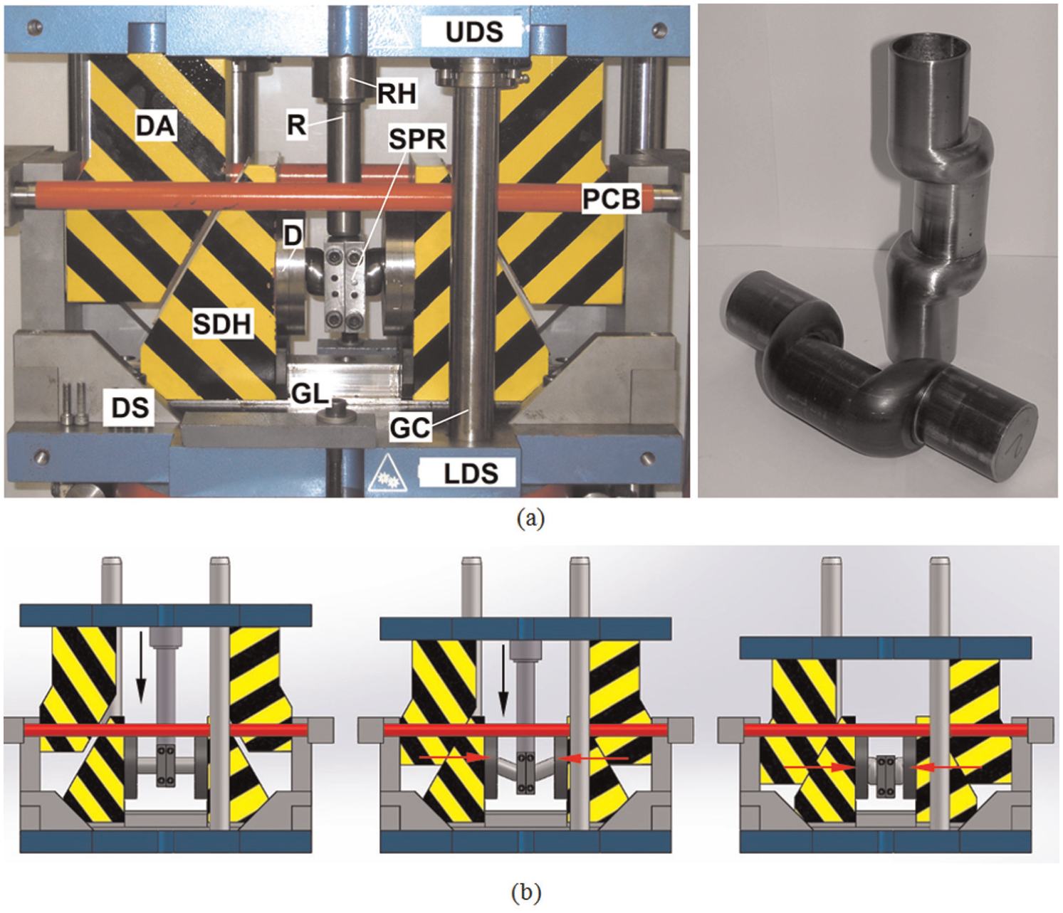
Tubular components with eccentric (gooseneck) cross sections produced by pressure-assisted forming with a solid medium. (a) Photograph of the double-action flexible tool system and tubular components after forming and after removing the solid medium and polishing. (b) Schematic representation of the three movements delivered by the tool system (left: vertical movement; middle: combined vertical–horizontal movement and right: horizontal movement).
The double-action tool system is based on a cam sliding mechanism and consists of structural- and process-dedicated parts (Figure 2(a)). The structural parts comprise a plurality of individual parts such as the upper die shoe (UDS), lower die shoe (LDS), the guiding columns (GC), the die segments (DS), the die actuator (DA), the sliding die holders (SDHs), the guiding lath (GL), the ram holder (RH) and the pre-compressed bars (PCB), which are independent of the geometry of the tubular components with non-concentric cross sections to be fabricated. The ram (R), the segmented pressure rings (SPRs) and the two dies (D) are the process-dedicated parts that are dependent on the initial and final geometries of the tubular components to be fabricated. In fact, by changing the ram, the SPRs and the dies, it is possible to produce tubular components with different geometries.
The vertical movement is accomplished through the independent movement of the ram (R) and is used to bend the tube during the initial preforming stage. This type of movement requires the DAs not to get in touch with the SDHs.
The combined vertical–horizontal movement is performed by simultaneous movement of the ram (R) and the SDHs and is employed to shape the side webs of the tubular gooseneck geometry by means of controlled plastic instability (buckling) under axial compression loading and internal pressure, as will be seen later in the presentation. This type of movement requires the ram (R) to touch the SPRs and the DAs to touch the SDHs in order to transmit the forming force through the mechanical cam system.
The horizontal movement is accomplished through the independent movement of the SDHs and is used to finish forming the tubular part by plastic instability (buckling). This type of motion requires the ram (R) not to get in touch with the SPRs.
Experimental work plan
The experiments were carried out in the double action tool system installed in the 1200 kN hydraulic testing machine where the mechanical characterization of the materials had previously been performed.
Straight tubular specimens of commercial S460MC carbon steel tubes with an outer radius
The different movements provided by the actuators of the double-action tool system;
The limiting amount of displacement s in the direction perpendicular to the longitudinal axis of the tube;
The initial unsupported length
The experimental work plan (terminology in accordance with Figure 1).
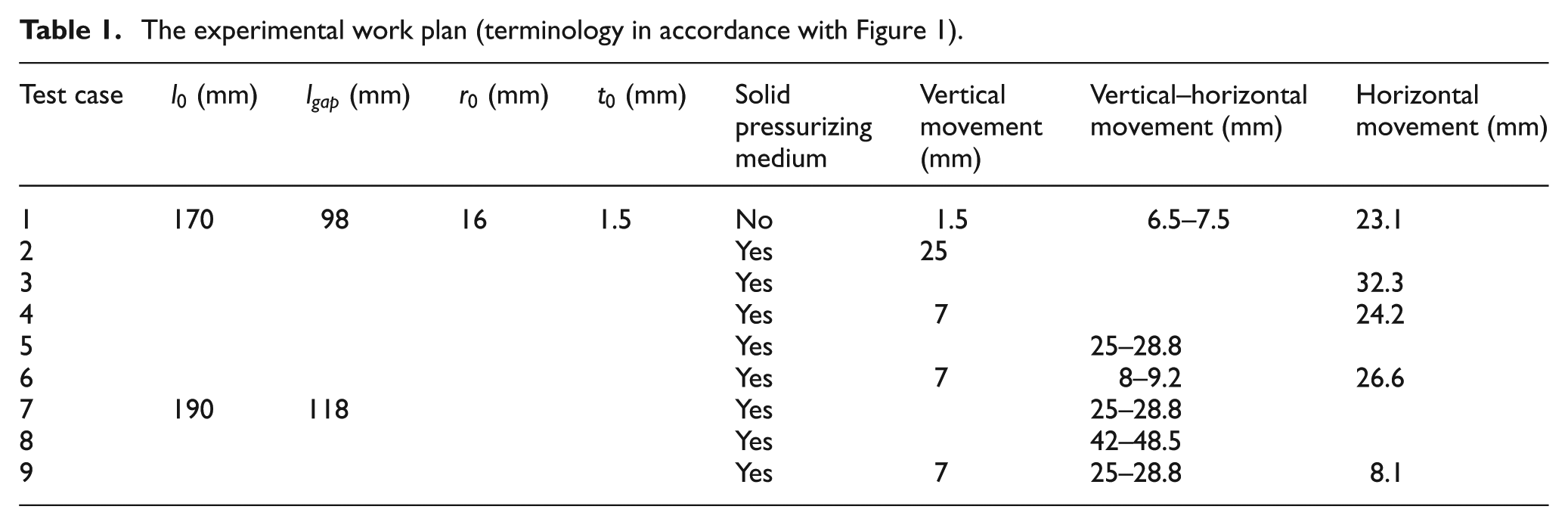
The investigation on the different movements of the actuators is very important because of their influence on the overall performance and feasibility of the process and on the total time required to produce a tubular component. In particular, the movement of the vertical actuator plays a key role in setting up the limiting amount of displacement s in the direction perpendicular to the longitudinal axis of the tube that an eccentric (gooseneck) tubular component is capable of withstanding without failure.
The initial unsupported length
The wall thickness
Lead was cast into cylindrical mandrels that were subsequently installed inside the straight tubular specimens, prior to forming, in order to assist plastic deformation and provide internal pressure to prevent collapse by buckling. The manufacturing process took advantage of material recyclability and mould reutilization because after forming the desired geometry of the tubular components, the mandrels were removed by heating and melting at a temperature of approximately 300 °C while leaving the tubular components intact and ready for subsequent cleaning and polishing.
In connection to this, it is important to state that the proposed technology is not limited to the utilization of lead and its alloys, which require removal by melting to be always performed in well-ventilated areas with good exhaustion of fumes in order to avoid poisoning by lead oxide. In fact, the only requirement of the proposed technology is the utilization of ductile, recyclable, low melting point alloys, and therefore alternative low melting point alloys made from bismuth and tin can easily replace lead with benefits for both environment and health.
The tubular specimens corresponding to Case 1 of Table 1 were tested without pressurizing medium (without internal mandrel) and included in the experimental work plan for reference purposes.
Finite element modelling
The manufacture of tubular components with non-concentric cross sections by pressure-assisted forming with a solid lead medium was performed under a quasi-static constant displacement rate of the UDS (100 mm/min). Under these conditions, no inertial effects on plastic deformation are likely to occur and therefore no dynamic effects needed to be considered.
These operating conditions allowed numerical modelling of material flow produced by plastic deformation to be performed with the finite element flow formulation and enabled the authors to utilize the in-house computer program I-form that has been extensively validated against experimental measurements of metal forming processes since the end of the 1980s. 17
The finite element flow formulation giving support to I-form is built upon the following extended variational statement accounting for contact and friction between different rigid and deformable objects
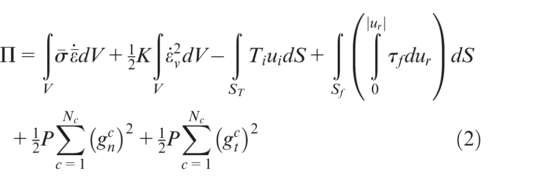
where
The last two terms in equation (2) account for contact between the counterfacing surfaces of the tube and the solid pressurizing medium. The contact is defined by
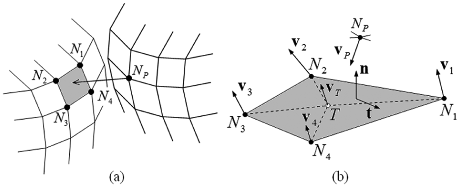
Schematic representation of a contact pair in the contact between the tube and the lead pressuring medium and associated notation. (a) Contact pair identified by nodal point
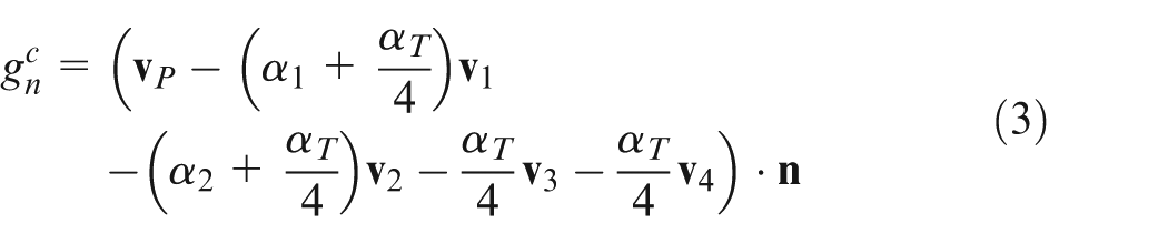
The normal gap velocity
and the tangential gap velocity
The normal gap velocity
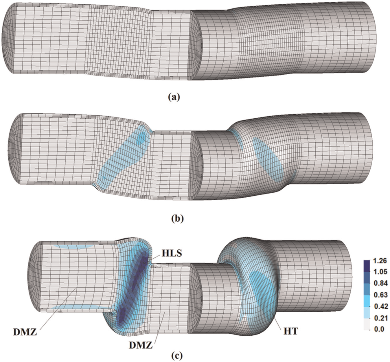
On account of symmetry, and because no anisotropy effects due to material or to the welding seam of the carbon steel tubes were taken into consideration, only one quarter of the initial straight tubular specimens and of the solid pressurizing medium needed to be discretized by means of hexahedral finite elements. Three layers of hexahedral finite elements were employed across the tube wall and no remeshing operations were needed to accomplish the final desired shape. The corresponding die and contact surface of the ram with the SPR were discretized by means of spatial triangular contact–friction elements as shown in Figure 4(a), whereas the pressure ring was discretized by a layer of hexahedral elements and modelled as a very stiff (nearly rigid) deformable body. The frictional effects were modelled by means of the law of constant friction with a friction factor
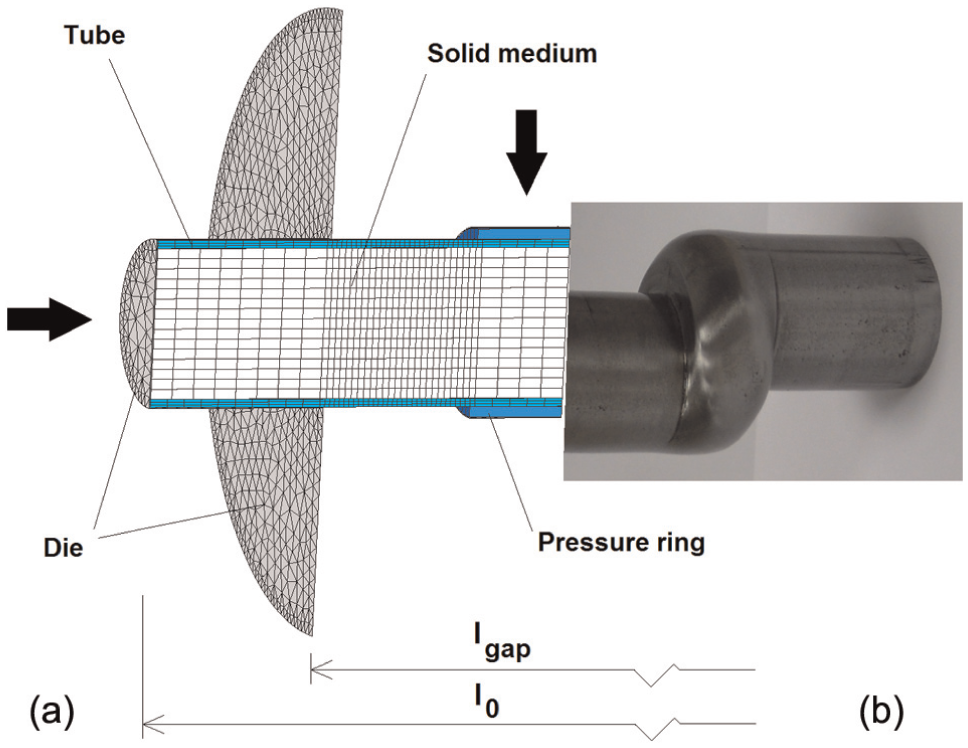
(a) Finite element model utilized in the numerical simulation of the manufacture of tubular components with eccentric (gooseneck) cross sections by pressure-assisted forming with a solid lead medium and (b) real tubular component at the end of the manufacturing process.
Figure 4(b) shows half of the real tubular part at the end of the pressure-assisted forming process. The overall CPU time for a typical analysis consisting of a structured mesh with approximately 9000 elements was approximately equal to 10 h on a standard computer equipped with an Intel Xeon E5-2620 (2.10 GHz) processor when using eight threads.
Results and discussion
Modes of deformation
Figure 5 presents the typical modes of deformation that occur during the manufacture of tubular components with eccentric (gooseneck) cross sections by pressure-assisted forming with a solid lead medium in a double-action tool system.
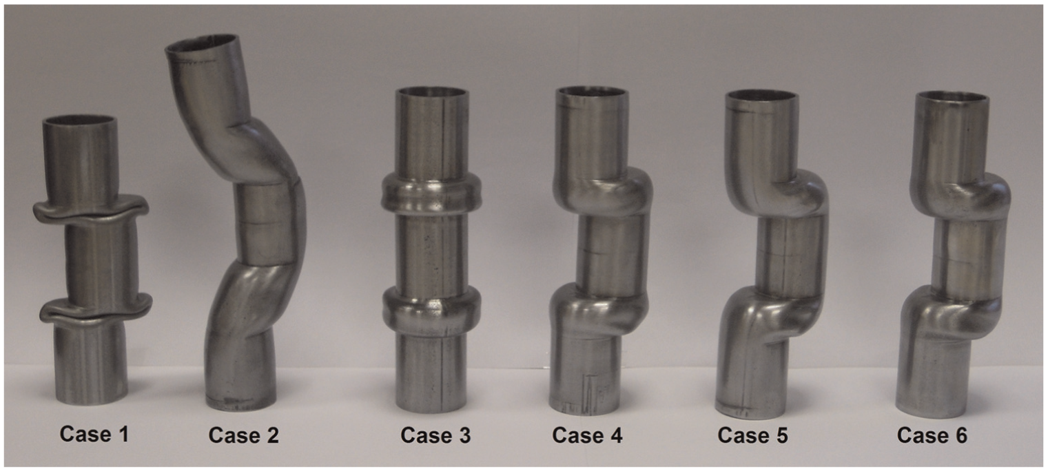
The mode of deformation of the leftmost tubular component (labelled as ‘Case 1’ in Figure 5) corresponds to collapse by buckling and reveals significant changes of the cross sectional shape from circular to elliptical due to absence of solid (lead) pressurizing medium. This mode of deformation is not appropriate to produce tubular components with eccentric (gooseneck) cross sections.
The mode of deformation of the following tubular component (labelled as ‘Case 2’ in Figure 5) corresponds to collapse by fracture in opening mode I (by tension) at the outermost region. This mode of deformation is also not appropriate to produce tubular components with eccentric (gooseneck) cross sections and is caused by an excessive stroke of the vertical actuator (in the direction perpendicular to the longitudinal axis of the straight tubular specimens) that produces a bended preform with inadmissible wall thinning in the outermost region of the tube subject to stretching (tensile elongation). Signs of localized necking can easily be observed in this region of the preforms before fracture.
The mode of deformation of the tubular component labelled as ‘Case 3’ (Figure 5) is also not appropriate to produce geometries with eccentric (gooseneck) cross sections because material flows uniformly around the axis of the original straight tubular specimen to form a concentric double-headed (rotational symmetric; Figure 1(a)) instead of a gooseneck geometry, as a result of local plastic instability. This result puts into evidence the key role played by bended preforms produced by the vertical actuator (imposing movement in the direction perpendicular to the longitudinal axis of the straight tubular specimens) whenever tubular components with non-concentric cross sections are to be produced.
The three remaining tubular components labelled as ‘Case 4’, ‘Case 5’ and ‘Case 6’ (Figure 5) exhibit eccentric (gooseneck) cross sections but were fabricated with different movements of the horizontal and vertical actuators of the double-action tool system. The specimen labelled as Case 4, for example, was produced by means of two independent movements of the actuators; first, the vertical actuator (ram) was forced against the pressure rings in order to produce a bended preform and, second, the horizontal actuator (sliding dies) finished shaping the tubular component by means of plastic buckling under axial compression and internal pressure. However, due to limitations on the amount of bending associated with the movement of the vertical actuator (refer to Case 2), this solution is not appropriate for producing tubular gooseneck components with large eccentricity (i.e. with large distance to the centre of the original cross section of the straight tubular specimen).
In contrast to Case 4, the tubular component labelled as Case 5 was fabricated in a single forming stage through combined action of the vertical and horizontal actuators. The main advantage of this solution over the previously mentioned procedure based on single independent actions of the vertical and horizontal actuators is the reduction in the total time required to produce a tubular component with gooseneck geometry.
Finally, Case 6 was produced by combination of single and multiple actions of the vertical and horizontal actuators. In the first stage, the vertical actuator (ram) forces the pressure rings against the straight tubular specimen to produce a bended preform and, as the upper tool shoe continues to descend, the DAs get in touch with the SDHs and start transmitting the horizontal force that is needed for material undergoing controlled plastic buckling under axial compression and internal pressure. Then, in the second stage, the vertical actuator (ram) is removed and the tubular component is finished by a final amount of plastic buckling imposed by the horizontal action of the sliding dies.
The finite element predicted shapes of the tubular component at an intermediate displacement of the first stage and at the final displacements of the first and second stages are disclosed in Figure 6 for Case 6. The predicted distribution of effective strain
Finite element predicted geometry and distribution of effective strain for Case 6 of Table 1 at a displacement of the upper tool shoe corresponding to the (a) end of preform bending, (b) end of the first stage and (c) end of the second and final stage.
The comparison between Cases 5 and 6 in Figure 5 also reveals that for similar amounts of displacement s in the direction perpendicular to the longitudinal axis of the straight tubular specimen, Case 6 is the best option because the larger curvature of Case 5 at the transition region from the original to the eccentric, displaced, cross sections is a consequence of higher stretching and thinning in the outermost walls.
The photographs enclosed in Figure 7 show how the initial unsupported length
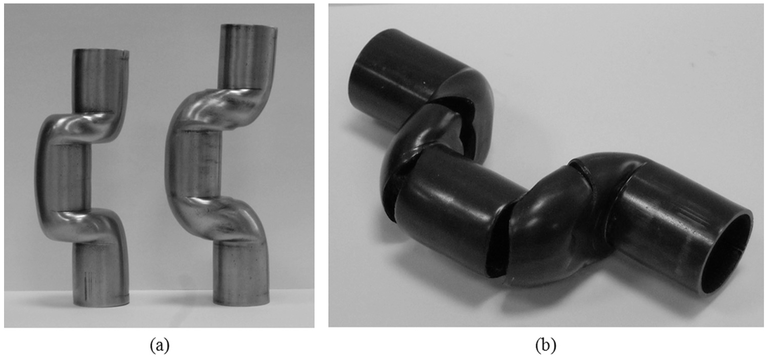
Influence of two main process parameters in the overall performance of the process. (a) Photograph of Cases 5 and 7 showing the influence of the initial unsupported length
As seen in Figure 7(a), both tubular components labelled as ‘Case 5’ and ‘Case 7’ are capable of withstanding displacements of the vertical actuator of the double-action tool system (in the direction perpendicular to the longitudinal axis of the tube) up to a limiting value
However, it is worth noting that apart from the extreme forming conditions of Case 7 and in close accordance with TRF, friction between the low melting point alloys and the tube wall is beneficial to form more uniform and wrinkle-free components than those produced by conventional THF.
Once the maximum achievable displacement is exceeded
Forming forces
Figure 8 shows the finite element predicted and experimental evolution of the load–displacement curve for Case 6 of Table 1. As seen, both evolutions compare well and allow distinguishing three different regions corresponding to the three different movements of the actuators of the double-action tool system: (a) independent movement of the vertical (ram) actuator (labelled as ‘A’), (b) combined movement of the vertical and horizontal actuators (labelled as ‘B’) and (c) independent movement of the horizontal (sliding dies) actuators (labelled as ‘C’).
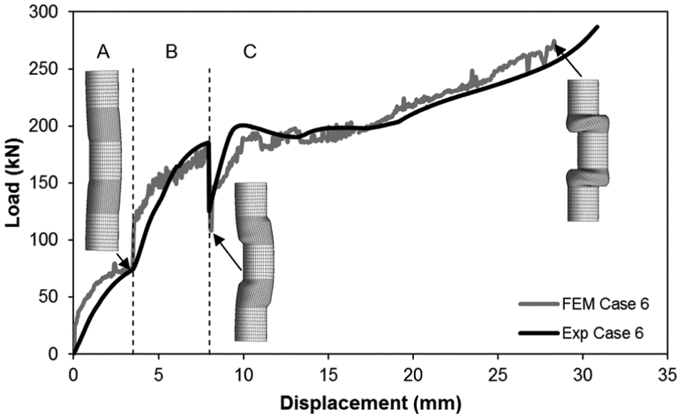
Experimental and finite element predicted evolution of the load with displacement of the upper die shoe for the manufacture of tubular components with eccentric (gooseneck) cross sections by pressure-assisted forming with a solid lead medium (Case 6 of Table 1).
In region A, the load increases monotonically towards a near steady-state value of approximately 70 kN as a result of bending the carbon steel tube filled up with lead by means of pressure rings in order to prevent wall collapse and loss of circularity along the eccentric (gooseneck) cross sections.
The sharp increase in the load up to 185 kN in region B is attributed to plastic deformation being carried out by simultaneous action of the vertical and horizontal actuators in what may be considered as controlled buckling under axial compression loading and internal pressure.
The drop in load at the beginning of region C is caused by the removal of the vertical actuator (region C), and the subsequent drop in load rate is justified by the increase in eccentricity with buckling, which progressively diminishes the need to increase the axial compression load.
The experimental evolution of the load with displacement for Cases 4, 5 and 6 that is illustrated in Figure 9 allows establishing a relationship between the existence or non-existence of the aforementioned regions A, B and C and the movements of the actuators that are utilized in each case. In fact, Case 4 only allows identifying two different regions (similar to regions A and C of Case 6), whereas Case 5 only allows identifying a single region (similar to region B plus C of Case 6).
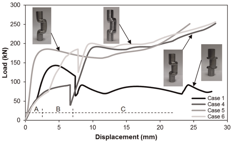
Experimental evolution of the load with displacement of the upper die shoe for the manufacture of tubular components with eccentric (gooseneck) cross sections for Cases 1, 4, 5 and 6 of Table 1.
The evolution of the load with displacement for Case 1 is included as a reference and shows the result of collapse by buckling due to the absence of pressurizing solid medium when combination of the vertical applied load and axial compression load exerted by the horizontal sliding dies reaches approximately 145 kN.
Conclusion
Pressure-assisted forming of carbon steel tubes using lead as a solid medium in a double-action tool system is a low-cost technological alternative to THF in case of low-batch production of tubular components with eccentric (gooseneck) geometries.
The use of lead or any other low melting point metallic alloy as a solid medium has the advantage of easy removal from the tubular components after forming and recyclability.
Adequate selection of the total amount of displacement s in the direction perpendicular to the longitudinal axis, the straight tubular specimens
The order of action of the vertical and horizontal actuators is very important for the overall success and quality of the tubular components. Best results are obtained with the utilization of three different actions applied in sequence: (a) preform bending by single action of the vertical actuator, (b) controlled buckling under axial compression load by combined action of the vertical and horizontal actuators and (c) finishing by buckling under axial compression load due to single action of the horizontal actuator.
Alternative solutions making use of just one or two different actions of the vertical and horizontal actuators may lead to failure or to fabrication of components with excessive curvature and thinning in the transition regions from the original to the eccentric, displaced, cross sections.
Footnotes
Acknowledgements
The work of Sara Gamboa is gratefully acknowledged.
Declaration of conflicting interests
The author(s) declared no potential conflicts of interest with respect to the research, authorship and/or publication of this article.
Funding
The author(s) disclosed receipt of the following financial support for the research, authorship, and/or publication of this article: This work is supported by the Fundação para a Ciência e a Tecnologia of Portugal under LAETA – UID/EMS/50022/2013 and by MCG – Mind for Metal, Carregado, Portugal. Paulo Martins would additionally like to acknowledge the support provided by Fundação para a Ciência e a Tecnologia of Portugal under SFRH/BSAB/105959/2015.