
Abstract
Off-axis aspheric mirror is an important component widely used in optical system and precision measurement instrument. Off-axis parabolic surface is one typical shape of off-axis aspheric mirrors which can enlarge focal length and widen field-of-view. Two typical ultra-precision turning methods which are turning the cylindrical blank by revolving around the axis of parabolic surface (TPS) and revolving around the axis of cylindrical surface (TCS) are analyzed and compared for off-axis parabolic surface in this article. Three-axis (X, Z, C) turning machine is applied and kinematic analyses of two linear axes (X, Z) are studied during cutting with the single point diamond turning. The tool paths are generated and installation errors are analyzed under two different conditions. Primary experiments are conducted to verify the effectiveness of theoretical analyses. The obtained results demonstrate that the surface machined with TPS method has better machining quality than the one machined with TCS method.
Keywords
Introduction
The off-axis aspheric mirrors enable systems to be established with less components, long focal length and wide field-of-view, which are important for space optical systems and precision-measuring devices versus the traditional mirrors.1,2 Off-axis parabolic surface is a typical shape among the off-axis aspheric surfaces and it plays a significant role in such fields as laser collimator, precision measurement instrument and astronomical telescope.3,4 An off-axis parabolic surface can be regarded as a part of rotation-symmetrical surface with a large off-axis value when it is rotated around the axis of the parabolic surface, whereas it also can be seen as a non-rotational symmetric surface when it is rotated around the axis of the cylindrical surface. These characters bring out a hard choice for machining an off-axis parabolic surface, especially for a parabolic surface with a large off-axis value.
Several manufacturing methods can be applied to machine the off-axis parabolic surface in previous research.5–7 Among the current machining methods, both grinding and fly cutting can generate the off-axis parabolic surface with high precision by rotating the tool and traversing either the tool or workpiece in three linear axes. However, these methods require long machining cycles and it is difficult to set-up. 8 Recently, single point diamond turning (SPDT) has become a standard machining process of producing precision optical surfaces in one-stage process without subsequent processing.9–11 The research has made great progress for freeform surface ultra-precision machining in recent years. For instance, Zhang et al. 2 proposed the coordinate transformation machining method to manufacture the off-axis aspheric mirrors with large off-axis magnitude by reducing the ratio of sag height to diameter and this method proved to be feasible. Yin et al. 9 investigated the off-axis parabolic surface generation in SPDT using slow tool servo and analyzed the form error caused by tool centering error. Kim et al. 8 proposed an approach which introduces the real-time error compensation technique for the thermal growth of spindle and straightness errors resulting from the guide ways of the diamond turning machine to obtain sub-micrometer surface using a fast tool servo.
However, few papers have been found to compare two different manufacturing methods with SPDT. This article discusses two typical manufacturing ways for off-axis parabolic surface, which are TPS and TCS during ultra-precision manufacturing with SPDT. For the machining process of TPS, several workpieces are evenly distributed on the spindle in the radial direction with a determined offset distance. Generally, profile accuracy of the workpiece fabricated with this method is affected by several factors, such as off-axis assembly position error, benchmark misalignment errors, interrupted cutting and alter-thickness machining errors, the unblocked situation of automatic chip removal and temperature stability about circulation coolant system.12,13 The most distinguishing feature of the machining process is that the X-axis and Z-axis are used while C-axis is ignored; therefore, positioning error of rotating C-axis can be eliminated in such case. For the machining process of TCS, the center line of cylindrical surface must be concentric with the center line of spindle in which it is installed. In this situation, C-axis has to be used for positioning in direction of rotation and the rotation error is induced subsequently.14,15 The process with this method is continuous cutting. The machining ability and accuracy are affected by the speed and acceleration of Z-axis since the movement of cutting tool is swing back and forth in Z-direction, so the machining efficiency of this process will be reduced. In addition, the cutting tool alignment error and benchmark misalignment error can also affect the machining accuracy.
This article is organized as follows. Section “Geometric design of cutting tool path” gives the geometric design of cutting tool path for two different machining methods. Section “Kinematic analyses of every motion axis” describes kinematic analyses of every motion axis under two distinct processes. Section “Comparison and analysis about installation error” analyzes the installation error under two different manufacture ways, and the experiments and corresponding results are presented in section “Experiments and discussion.” Finally, the section “Conclusion” draws the conclusions.
Geometric design of cutting tool path
Generally, for a SPDT system, the machining system should be expressed in a cylindrical coordinate (X, Φ, Z). 16 Then, the desired off-axis parabolic surface can be described as
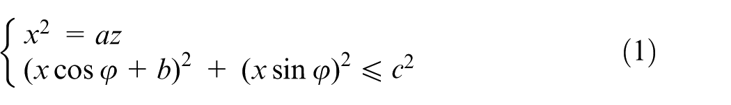
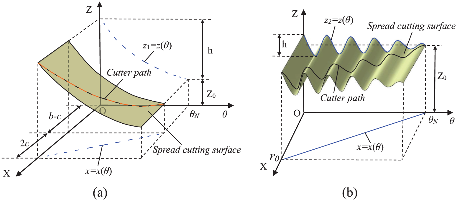
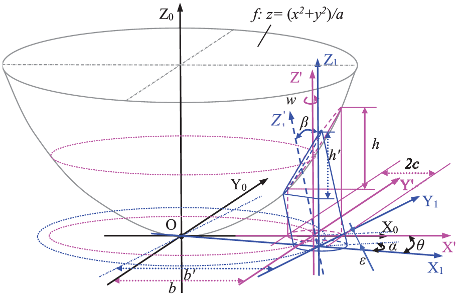
where a is a double radius of curvature of the parabolic surface, and b, c are the offset distance and the radius of cylindrical surface, respectively. Obviously, an off-axis parabolic surface is a part of a parabolic surface as shown in Figure 1 and Figure 1 also analyzes the different coordinate systems about two different cutting methods. Coordinate system used to generate the cutting path of the parabolic surface in TPS model is displayed in a Cartesian coordinate (X, Y, Z), as shown by Figure 1(a). Another coordinate system used to generate the cutting path in TCS model is presented in a Cartesian coordinate (X0, Y0, Z0) shown in Figure 1(b). In fact, the new coordinate system (X0, Y0, Z0) is obtained by moving the original coordinate system (X, Y, Z) for distance of b millimeters along X-direction, as illustrated in Figure 1(b). After determining the coordinate systems for the two machining models, generations of the cutter paths can become slightly easy.
The schematic diagram of off-axis parabolic surface: (a) TPS model and (b) TCS model.
In cutting aluminum workpiece, negative rake angles are typically used in industrial practice. Since the effective rake angle may be changed in various undeformed chip thicknesses, a 0° rake angle tool is actually can give better cutting results than negative rake tool.17,18 In addition, 0° rake angle is convenient for tool path generation. 19
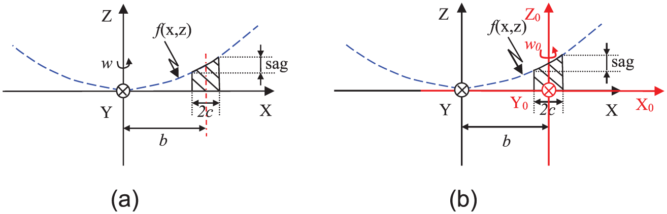
A more efficient and suitable method used to generate a cutting tool path is projecting points on a planar spiral curve to a desired surface.20,21 To obtain a tool path in TPS model, a planar spiral curve with max radius (b + c) is generated and then projected to the parabolic surface defined by equation (1), as shown in Figure 2(a), and then the cutter contact points are obtained. As for TCS model, a planar spiral curve with max radius c is generated whose center is located on (b, 0) in XOY-plane. The planar spiral curve is projected to the same parabolic surface, as shown in Figure 2(b) and the path of cutter contact points is produced.
Models of generated tool path: (a) tool path generated in TPS model and (b) tool path generated in TCS model.
The cutting tool paths produced by the above method are the paths of cutter contact points. In designing the numerical control (NC) programming, the path of the center of tool radius needs to be calculated, which is known as cutter position. That is to say, the cutting tool compensation (ΔX, Δφ, ΔZ) have to be intensively studied.22–24 According to the real cutting circumstance, ΔX and Δφ are affected by the spacing between two adjacent trajectories, the value of curvature about cutting path along X-direction on the cutting plane (XZ-plane) and a fraction of tool radius size. The programming paths are calculated using the tangent condition between the tool tip arc and designed off-axis parabolic surface at the cutter contact points, as seen from Figure 2, and this method can only be used under the condition of 0° rake angle.
Kinematic analyses of every motion axis
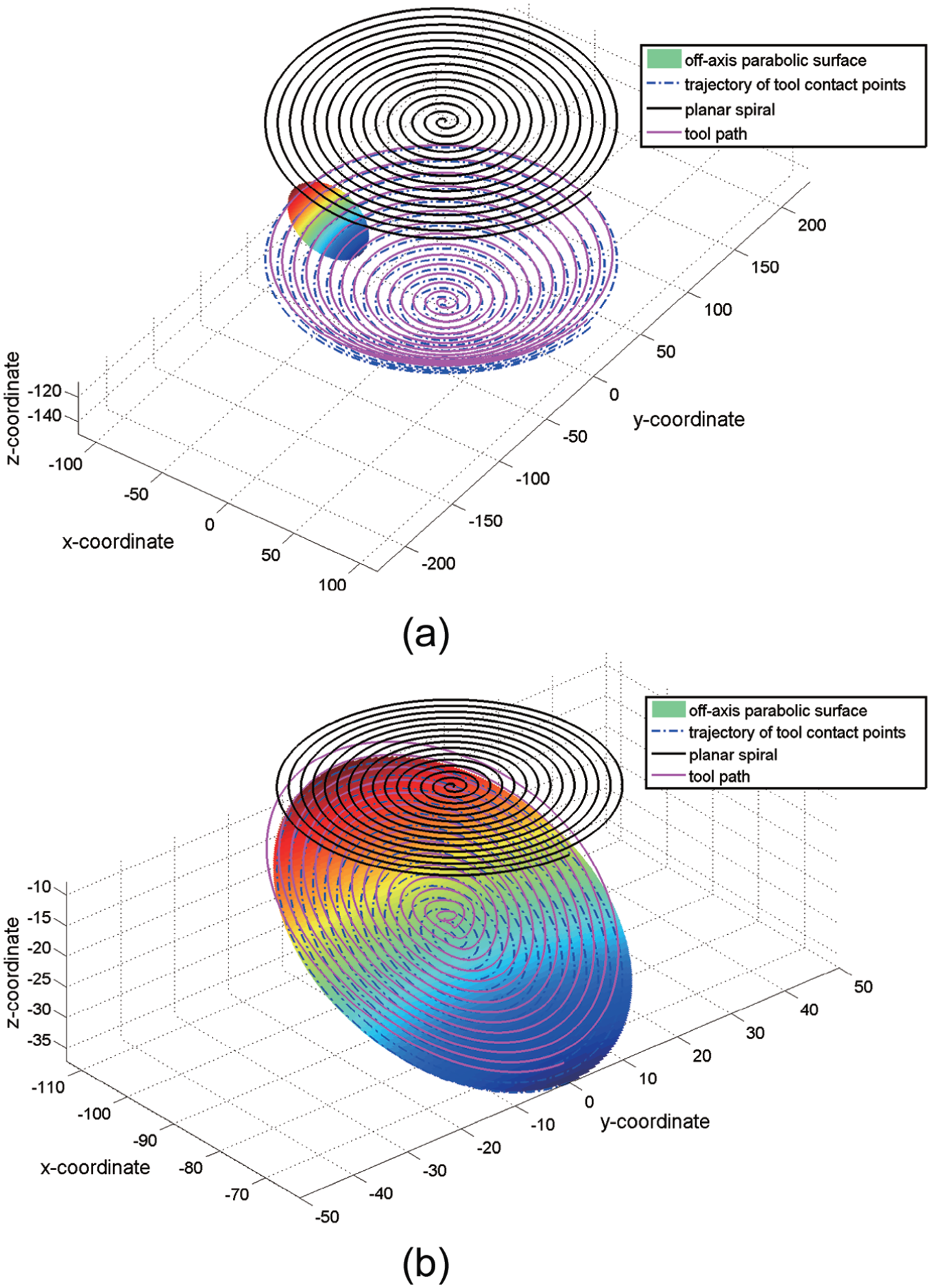
To analyze the motion feature and compare the fabricating precision and efficiency of the two machining processes, it is necessary to study the displacements, speeds and accelerations of every axis through kinematic analysis. 25 In recent literature, Keong et al. 26 found that Z-axis retraction affects the geometrical accuracy and surface quality of workpiece significantly. Liang et al. 27 built a dynamic model considering the influence of joint characteristics. The principle diagram of diamond turning is displayed in Figure 3(a), obviously in the process of machining, the cutter points on the cutting trajectory pass through the tip of diamond tool in a specified sequence. In order to give a clear expression, along with the cutting path the cutting procedure is spread from the start cutting point to the end point in a counterclockwise direction, as demonstrated in Figure 3(b). With this developed strategy, the movement of cutter point in Z- and X-axes changing with angle of rotational C-axis can be deeply studied.
The cutting model of SPDT: (a) the cutting principle diagram and (b) the expanded view of desired surface.
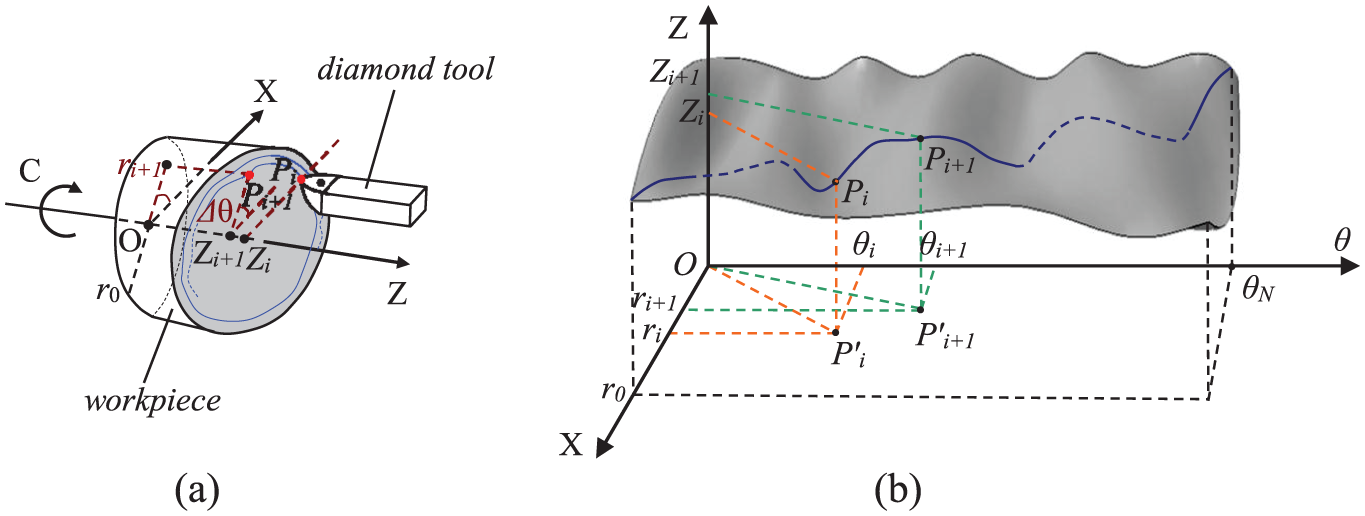
For machining in TPS model, Figure 4(a) gives the expansion graph about the cutting procedure. It is evident that the displacement of the X-axis is linear with respect to the angle of the spindle C-axis discontinuously. While, the relationship of displacements between Z-axis and angle of spindle C-axis can be given as
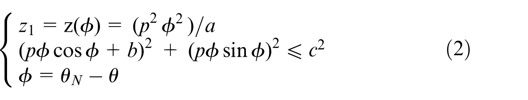
where θN refers to the rotated angle of C-axis from the begin to end during SPDT. θ is the rotated angle of C-axis from the begin to any moment in machining process. Variable p represents the base polar radius of the planar spiral. From equation (2), it can be seen that the displacement of Z-axis can be defined as a quadratic function Z(θ) and the variable θ of the function is given as the angle displacement of the spindle C-axis. Therefore, with gradual increasing about the angle displacement of the spindle C-axis, values of the X- and Z-coordinates are decreasing gradually. This means there is no need to use slow servo for any motion axes. So, the spindle rotate speed usually can be set to a large value and the move speed of X-axis can be set to a small one. In the following actual processing experiments, the parameters of 450 r/min and 1.5 mm/min are chosen as the spindle rotate speed and the move speed of X-axis. In addition, a small segment of cutter path about the machining surface is passed while the spindle is rotating in a circle, and this process is an interrupted cutting.
Kinematic analysis of two different manufacturing methods in coordinate system (X, θ, Z): (a) TPS model and (b) TCS model.
As for the fabricating approach in TCS model, an expanded view is shown to convey the cutting procedure in Figure 4(b). Obviously, the displacement of the X-axis is linear with respect to the angle displacement of the spindle C-axis continuously and the relationship of displacements between Z-axis and angle of spindle C-axis can be provided by
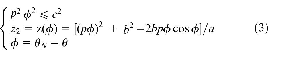
From equation (3), it means that the moving coordinates of Z-axis are constructed to be a function, which including a cosine function of rotation angle about the spindle C-axis and the amplitude of the cosine function, the amplitude of the cosine function is gradually decreasing with the increasing in rotational angle and finally to zero. From the above analysis, it can be seen that both magnitude and direction of velocity about Z-axis are required to be discontinuous changing with the increase in rotational speed about C-axis. Therefore, the slow slide servo of the Z-axis and the C-axis must be used to provide a real-time accurate displacement control. So, the efficiency of the machining is strongly affected by the limits of the speed and the acceleration about every axis of the machine.
Comparison and analysis about installation error
In the course of machining process, fixing methods and error in mounting workpiece usually influence the processing precision of a part. To compare the two different workpiece clamping methods, here gives a brief analysis about the effect of installation errors for each method.
Figure 5 shows the schematic diagram of installation errors which exist in X-, Z- and C-axes during machining process in TPS model. Theoretically in this way, several workpieces are evenly distributed on the spindle in the radial direction with a determined offset distance. Actually, it is inevitable that there will exit three linear positioning errors Δx, Δy, Δz and three rotational errors Δα, Δβ, Δγ in coordinate system or corresponding installation errors Δρ, Δθ, Δz, Δα, Δβ, Δγ in cylindrical coordinate system. 28 Installation error is studied in the cylindrical coordinate system, as displayed in Figure 5. Here, installation error Δz can be ignored, for machining precision of surface cannot be affected by it. Δρ is a difference value between polar radius b′ and b; Δθ is an angle error in plane polar coordinate, and Δα is a rotational error around the axis of the center axis of the part. There is always an intersection angle Δβ due to un-parallelism between Z-axis and center line of cylindrical workpiece in practical workpiece installation experiment, which is constructed by the other two rotational errors Δβx and Δβy. All these influencing factors will lead to sagittal height variation in Z-axis for off-axis parabolic surface and distance variation in radial direction between center line of parabolic surface and center point of the machined surface of the spindle.
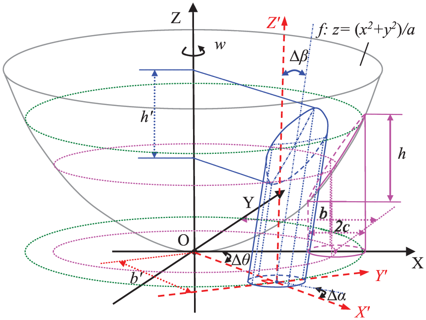
Installation errors exist in every axis under TPS model.
The two variations are presented by Δh1 and Δr1, respectively. The error Δh1 in height of surface can be expressed as
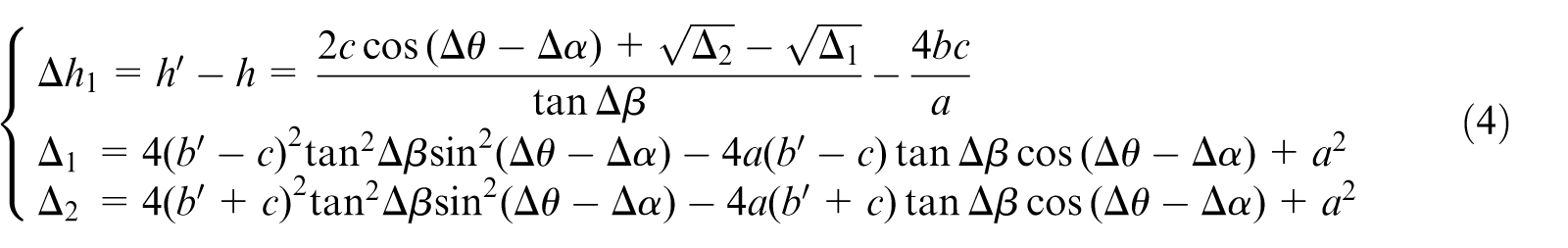
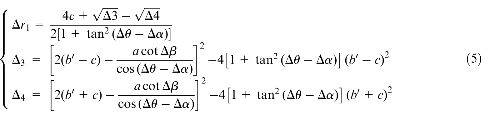
The error Δr1 in the radial direction of the spindle can be given as
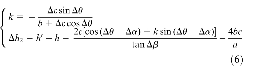
For the machining process in TCS model, a similar method is used to analyze the fixture errors. In this way, the workpiece is mounted on the spindle with the coaxial line of their center lines. It is convenient that the installation error is studied in the cylindrical coordinate system as displayed in Figure 6. Here, Δε is the distance between center points of ideal location and real installation cylinder in fixture plane, an angle error Δθ in plane polar coordinate is a deflected angle rotate around the center of the parabolic surface, an angle error Δα is a rotational angle revolve around the center line of the cylinder, the angle error Δβ is an intersection angle between Z-axis and the center line of cylindrical workpiece. The sagittal height variation in Z-axis and distance variation in the radial direction can be presented by Δh2 and Δr2, respectively. The error Δh2 in height of surface can be expressed as
Installation errors exist in every axis under TCS model.
The error Δr2 in the radial direction of the spindle can be given as
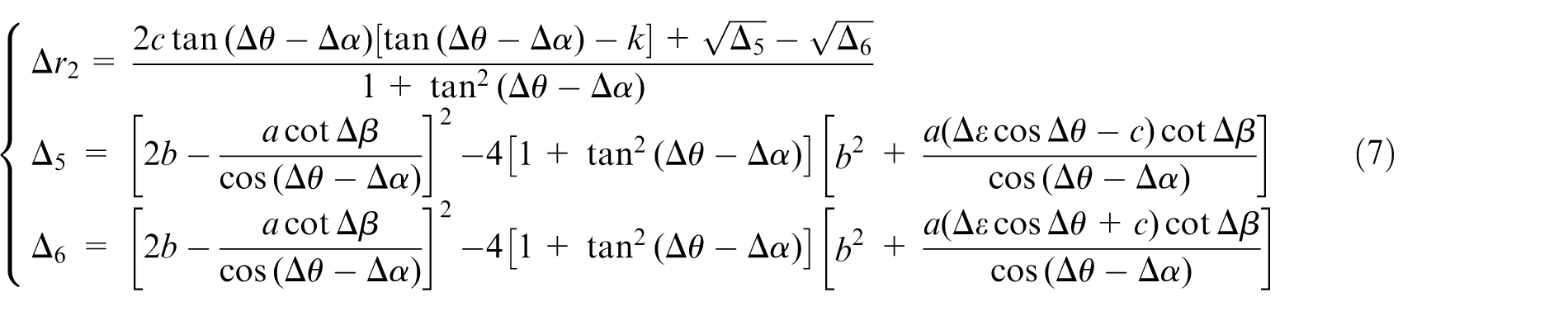
Based on equations (4)–(7) mentioned above, it can be seen that installation errors Δh1, Δr1 in TPS model and Δh2, Δr2 in TCS model are both determined by several constants (a, b, c) of the off-axis parabolic surface and fixture errors (Δα, Δβ, Δθ, b′) in every axis. It can be indicated that there are four factors (Δα, Δβ, Δθ, b′) that affect the installation errors for the same parabolic surface under two different machining models. The equivalent condition is made which keeps the value different between b and b′ in TPS model equal to the deviation Δε in TCS model. To analyze the different effect of fixture errors (Δα, Δβ, Δθ) on installation errors for the two machining methods, simulation comparison is done in condition of setting a fixed value and changing other two variables.
As shown in Figure 7, it can be seen that the height error Δh2 and radial error Δr2 in TCS model are both larger than these ones in TPS model under condition of a determined Δβ and two varied Δα and Δθ. Figure 8 reveals that the height error Δh2 in TCS model is almost equal to height error Δh1 in TPS and radial error Δr2 in TCS model is larger than the error Δr1 in TPS model in condition of a determined Δα and two varied Δβ and Δθ. As seen from Figure 9, the height error Δh2 in TCS model is almost equal to height error Δh1 in TPS model and radial error Δr2 in TCS model is larger than the error Δr1 in TPS model on condition that Δθ is a fixed value and Δα and Δβ are two variables. So, the installation errors have bigger influence on TCS model than in TPS model for a same surface.
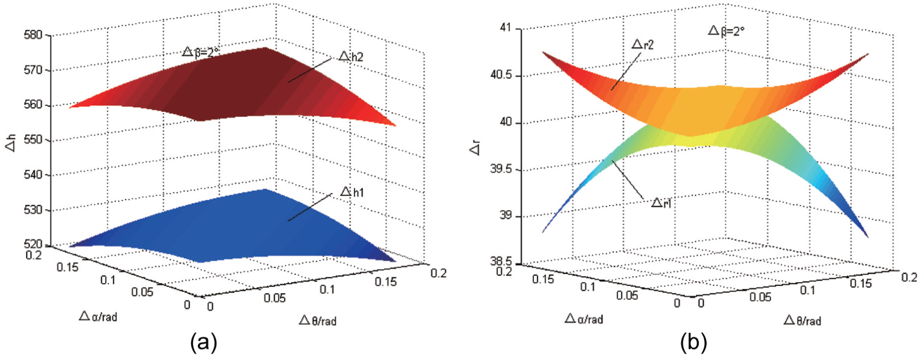
Installation errors distribution map when Δβ = 2° and changes of variables Δα and Δθ: (a) error Δh in height of surface and (b) error Δr in the radial direction.
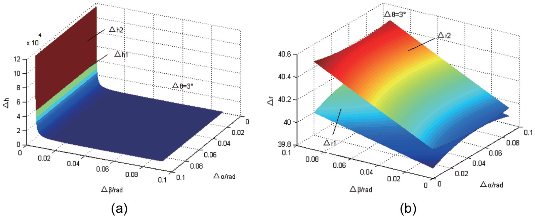
Installation errors distribution map when Δα = 2° and changes of variables Δβ and Δθ: (a) error Δh in height of surface and (b) error Δr in the radial direction.
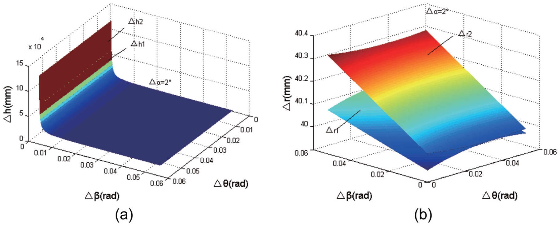
Installation errors distribution map when Δθ = 2° and changes of variables Δα and Δβ: (a) error Δh in height of surface and (b) error Δr in the radial direction.
Experiments and discussion
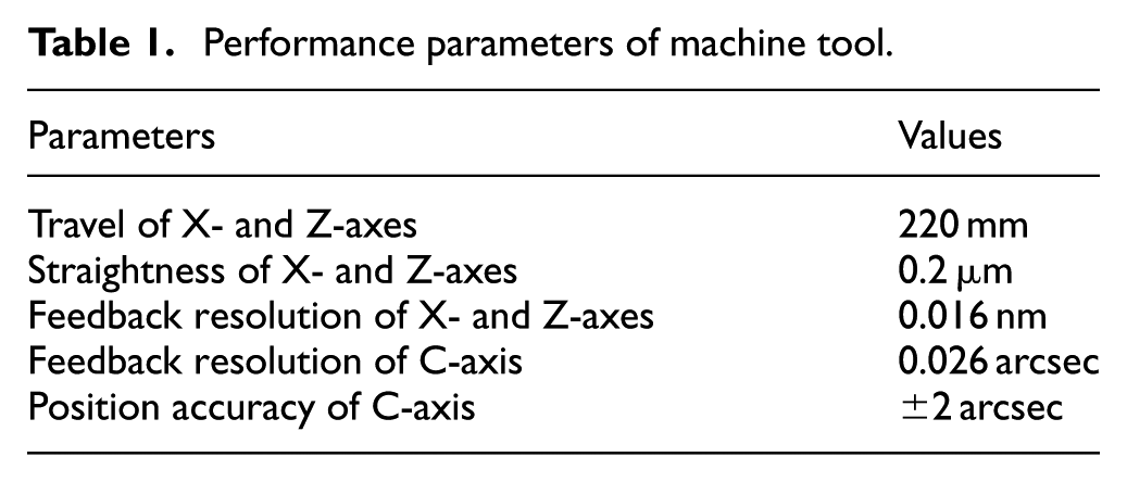
The machine used for experiments with two different machining methods is a Nanoform 250 ultra-grind machining system, which consists of two linear hydrostatic oil-bearing slides (X, Z) in a T-configuration. An air-bearing spindle is mounted on the X-slide, which can act as a rotary C-axis. The performance parameters of the used machine are listed in Table 1.
Performance parameters of machine tool.
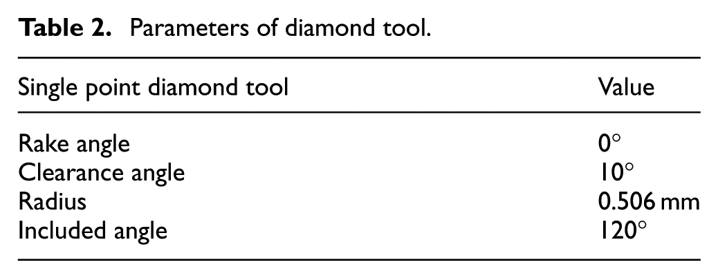
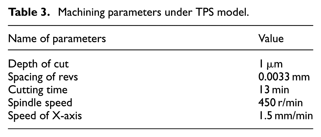
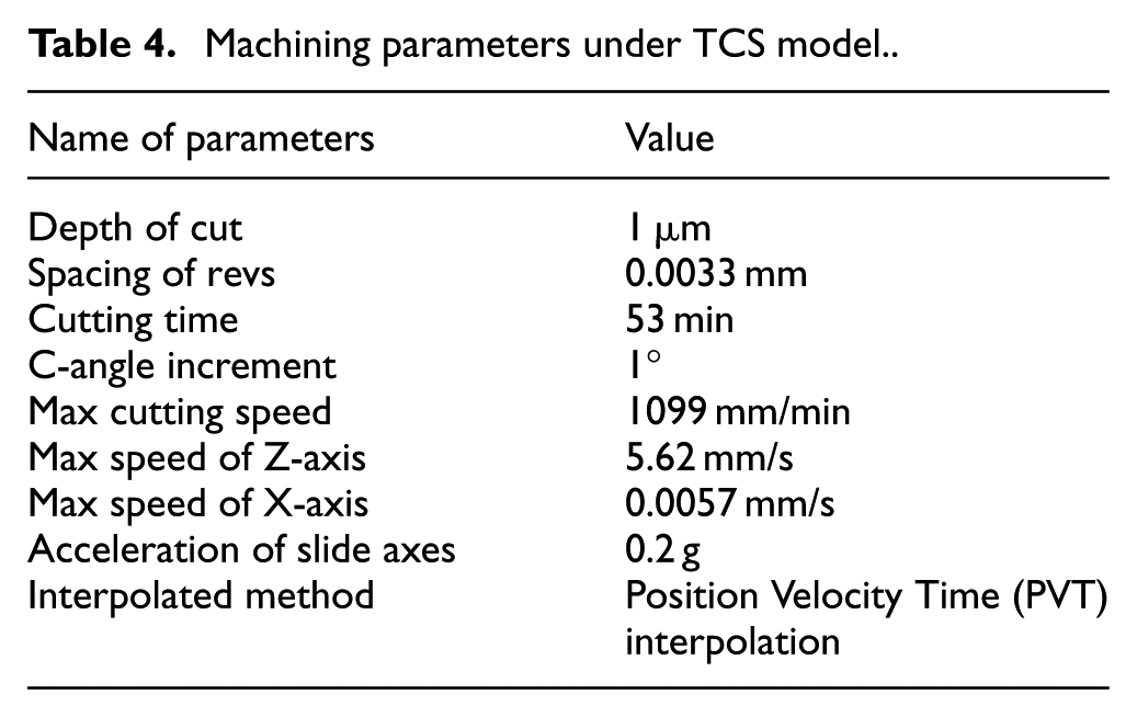
Before machining the off-axis parabolic surface, three aluminum Al6061 cylinders with c = 10 mm in equation (1) were roughly milled by a three-axis milling machine. The off-axis parabolic surface with a = 780.8 mm and b = 53.5 mm is chosen to process the ultra-precision machining with the two different methods. The parameters of diamond tool used to cut the surface are listed in Table 2. Machining parameters in condition of two different methods are presented in Tables 3 and 4, and it can be seen that cutting an off-axis parabolic surface with a common equation in TCS model needs more time than in TPS model. The practical machining processes are shown in Figure 10.
Parameters of diamond tool.
Machining parameters under TPS model.
Machining parameters under TCS model.
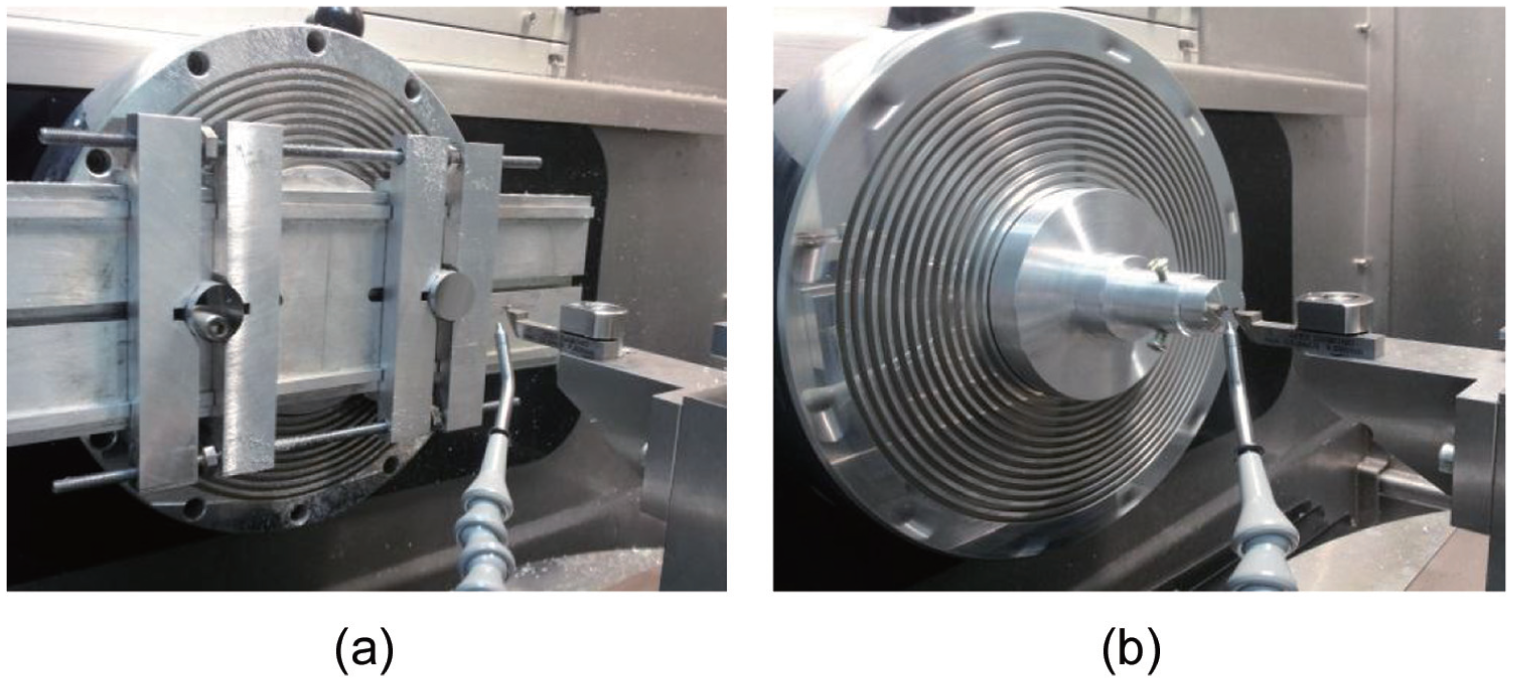
Practical machining photos: (a) TPS model and (b) TCS model.
After centering tool by video tool set station linear variable differential transformer (LVDT) and dynamic balancing the spindle, workpieces were cut and tested by a high magnification microscope Contour GT and a precision form measurement system Talysurf PGI 1240. The measuring results show that values of surface roughness were 2.2 nm (Ra) and 4.0 nm (Ra) in TPS model and TCS model in the square of 60 × 45 µm, respectively, as presented in Figure 11(a) and (b).
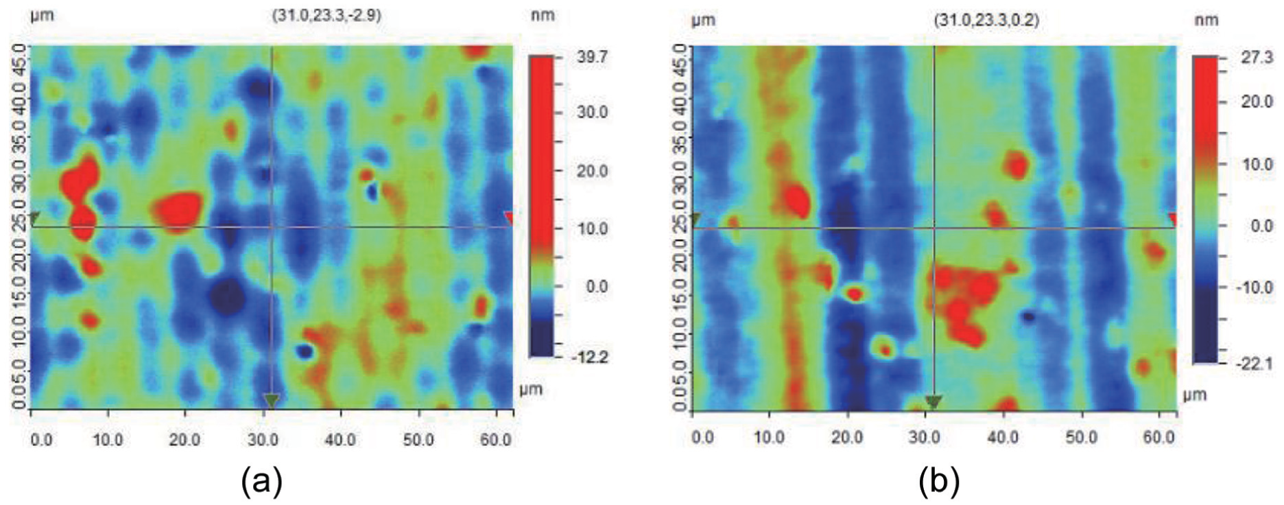
Surface finish measured by the Contour GT: (a) TPS model and (b) TCS model.
Form errors are obtained through a precision form measurement system Talysurf PGI 1240 as given by the Figure 12(a) and (b). The form error of machined off-axis parabolic surface is 0.22 µm in TPS model. As for original measurement graph of form error in TCS model in Figure 12(b), form error is 2.6 µm.
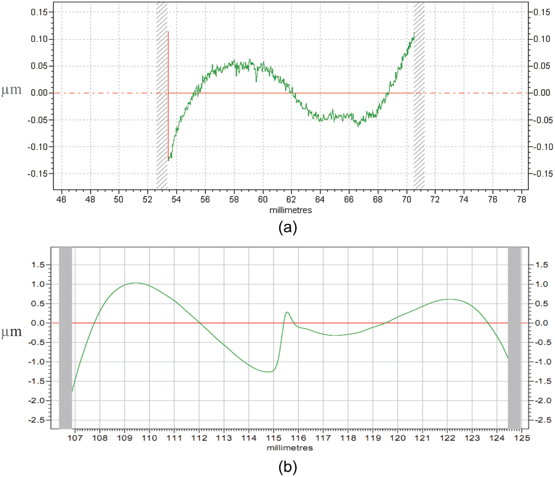
Results of form error: (a) surface fabricated in TPS model and (b) surface fabricated in TCS model.
From the above tested results, under the same processing condition, it can be seen values of surface roughness and form error in TPS model are smaller than those obtained in TCS model. Furthermore, the machining process in TCS model wastes more time than that in TPS model.
Conclusion
Tool path generation, kinematic analysis of motion axis and analysis of fixture installation error are studied theoretically for the ultra-precision machining of off-axis parabolic surface under two different models in the article. Machining and measuring experiments are done in the final part of the article. Based on the findings, the following conclusions can be drawn:
For a machine with a fixed travel of motion axis, a bigger off-axis parabolic surface can be fabricated in TPS model than in TCS model. The larger the off-axis value is, the smaller an off-axis parabolic surface can be made in TPS model.
Slow tool servo is indispensable in TCS model, whereas it is not needed in TPS model. Therefore, efficient of machining in TPS model is more high.
Values of surface roughness and form error about an off-axis parabolic surface in TPS model are smaller than those corresponding values in TCS model. In order to obtain a more precision off-axis parabolic surface, TPS model is a more reasonable choice on condition that workpiece dimensions meet the requirements.
An off-axis value adjustable and symmetrical distributed mounting workpieces fixture must be designed and manufactured in TPS model which bring out machining difficult and need a more precision fixture. On the contrary, a more simply and easily manufacturing fixture is necessary in TCS model which can provide a more accuracy connection between the workpiece and the spindle.
Synthetical installation error in TCS model is bigger than the synthetical error in TPS model with all other single axis fixture errors equal. Therefore, to obtain a high precision workpiece, TPS model should be adopted rather than TCS model in consideration of synthetical installation error.
Footnotes
Declaration of Conflicting Interests
The author(s) declared no potential conflicts of interest with respect to the research, authorship and/or publication of this article.
Funding
The author(s) disclosed receipt of the following financial support for the research, authorship, and/or publication of this article: This work is supported by the National Key Basic Research and Development Program (973 program) of China (grant no. 2011CB 706702), Natural Science Foundation of China (grant nos. 51305161 and 51135006) and Jilin province science and technology development plan item (grant no. 2013 0101042JC).