
Abstract
In laser-induced thermal-crack propagation, thermal stresses control the crack propagation mode and the quality of the crack surface. In this article, the 1064-nm semiconductor laser as a volumetric heat source is used for symmetry and asymmetry cutting glass. One of the problems in laser asymmetry linear cutting glass with laser-induced thermal-crack propagation is the quality of the crack surface which gets worse than that in symmetry cutting. This study lays great emphasis on analyzing the effect of the focus position and shear stresses on the crack sectional shape in semiconductor laser asymmetry linear cutting glass. This article indicates the volumetric heat flux formula, which simulates the temperature distribution from the material above or below the focal point. The heat source should be positioned above the focal point. Optical microscope photographs of the crack surface and sectional shape are obtained to examine the surface quality which is explained from the results of the stress fields using the extended finite element method simulation. In asymmetry cutting, shear stress is parallel to the crack surface and perpendicular to the cutting direction, which makes the crack surface smooth but uneven.
Introduction
With the advancements in glass industry, glass has better material properties. The glass is widely used in construction, electronics, automotive, flat panel display and mobile phones industries. A desired shape and size of the glass can only be obtained through precise cutting technique.1–4
The conventional cutting technique used to cut glass is to scribe and break. A groove weakening the glass surface is scribed using a diamond blade or a focused laser. Then the groove extends through the glass for complete separation using mechanical bending or the non-focused laser.5–7 Although the method is relatively simple, it usually causes many defects such as chips formation, irregular cut path, micro-cracks and even broken material. These defects decrease the strength and yield of flat glass. The laser-induced thermal-crack propagation (LITP) can eliminate the above defects because it uses less non-focused laser power and does not produce the groove on the glass surface.
LITP makes the material have the initial crack to produce an uneven temperature field, maximum temperature cannot soften or melt the material, and induces the thermal stress. The initial crack separates along the cutting path, when the tensile stress exceeds the failure stress given by the following equation (1)
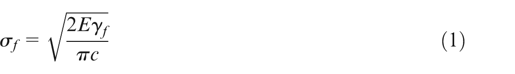
where
Lumley 9 first proposed the LITP for cutting of brittle material such as alumina ceramic substrate and glass, by using a CO2 laser. Tsai successfully used CO2 laser and pre-bending to cut liquid crystal display (LCD) glass with controlled fracture and divided the cutting process into three stages: initiate, stability and instability.7,10,11 Yenliang and Jehnming 12 constructed a multiple laser system consisting of CO2 line-shaped and Nd-YAG pulsed lasers to cleave a soda-lime glass. Yukio indicated that crack formation and crack propagation are two steps in LITP cutting glass. The preset crack is from 5 to 75 µm defects. 13 Lin Li used a diode laser to cut soda-lime glass. The effect of cut deviation at the leading and trailing edges of the glass with different laser beam geometries and laser output modes was reported.14–17 Yang et al. 18 studied the technique of Nd-YAG laser cutting of multi-layer glasses, which improved cutting efficiency.
These results were based on the research of symmetric cutting using different laser types. The cutting quality from Nd-YAG laser (volumetric heat flux) is better than from CO2 laser (surface heat flux). In the simulations, most of the researchers had ignored the dynamic extension of crack and assumed the uniform temperature across the thickness of the glass. In the cutting experiments, most of the researchers had only carried out the experiment below the laser focus to cut glass. However, these simulations and experiments are not accurate enough and the asymmetrical linear cutting (cutting line not along the median plane) is more common in the actual production. For instance, in the process of LCD screen and cover lens, asymmetrical linear cutting is the main mode of cutting. The quality of crack surface influences the application of technology in asymmetrical linear cutting glass with LITP. So it is necessary to understand the real temperature distributions and thermal stress distributions with the crack propagation in cutting process.
This study lays great emphasis on analyzing the effect of the focus position and shear stresses on the crack sectional shape in semiconductor laser asymmetry linear cutting glass. In this article, a 1064-nm semiconductor laser as a volumetric heat source is used for symmetry and asymmetry cutting glass with LITP. The volumetric heat flux formula is presented. The temperature distributions are studied by the simulation and experiment with the heat source below and above the laser focus. In order to explain the surface quality, the extended finite element method (XFEM) is used to simulate the real thermal stress distributions, the crack propagation process and the crack sectional shape. This work indicates a better cutting method with a heat source above the laser focus and provides a theoretical basis to improve the quality of the crack surface in laser asymmetry linear cutting glass with LITP.
Volumetric heat flux
According to the absorption capacity of the material to different wavelengths of laser, the laser heat source is divided into the volumetric and surface heat, as shown in Figure 1. The temperature rise of the material about volumetric source is mainly due to direct energy absorption, while surface heat source depends mainly on heat transfer. In this article, the form of glass absorbing semiconductor laser (1064 nm) is volumetric absorption. Consider the impacts of the laser divergence angle and heat source position on temperature distribution. Establish the rectangular coordinates (O, x, y, z) and the cylindrical coordinates (O, r, θ, h), as shown in Figure 2(a) and (b). The heat flux density q (r, θ, h) is the Gaussian distribution at point (r, θ, h) written as the following equation (2)
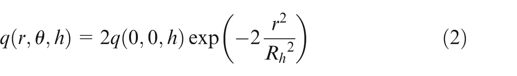
where q (0, 0, h) is the heat flux of the centerpoint on the cross section at height h.
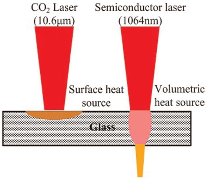
Laser heat source type.
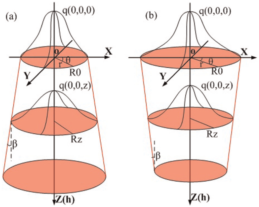
Specimen of coordinate system for the volumetric absorption: (a) below the laser focus and (b) above the laser focus.
According to Beer–Lambert law and laser divergence angle, the laser intensity exponential decays along with the propagation distance h. The heat flux q (0, 0, h) can be obtained as equation (3)
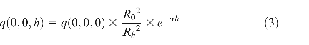
where α is the absorption coefficient of the material to laser,
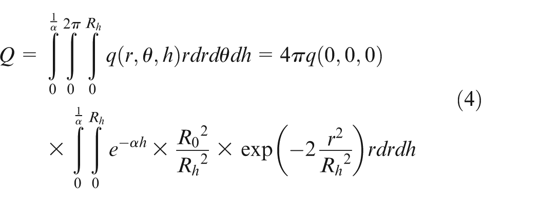
Laser power Q which is equal to the total heat input power can be written as the following equation (4)
The laser beam maintains a constant TEM00 mode and travels with a constant velocity v. The volumetric heat flux of the moving laser can be expressed in Gaussian distribution as equation (5)
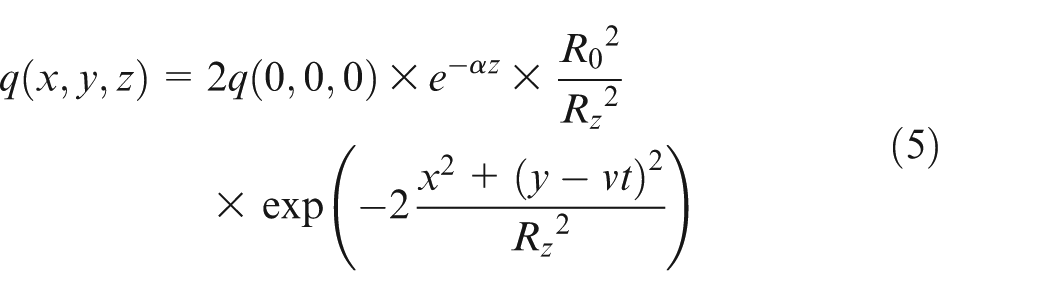
The real temperature distributions can be obtained by this volumetric heat flux.
XFEM simulation
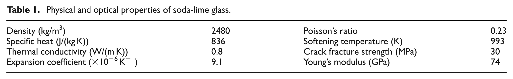
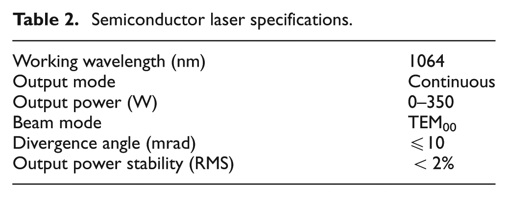
A three-dimensional (3D) dynamic extension of crack analysis was carried out using FE software ABAQUS to simulate the effect of thermal stresses on semiconductor laser cutting glass. The sequentially coupled thermal stress analysis can decouple into two distinct analytical models: transient thermal analysis and dynamic propagation of crack analysis. The thermal and physical properties of the material were used in the analysis, as given in Table 1. The laser specifications are given in Table 2. A DFLUX user subroutine was written in FORTRAN to define the moving volumetric heat flux. 19
Physical and optical properties of soda-lime glass.
Semiconductor laser specifications.
A 3D entity element DC3D8 with eight nodes was used in the transient thermal analysis, while a 3D entity element C3D8R with eight nodes was used in the extended FE model Figures 3 and 4. 19 In the XFEM, the initial crack was defined by 3D shell element, which was assigned contact properties. The maximum main stress failure criterion was the damage criterion of fracture initiation. The damage evolution (fracture extension) was based on the energy and linear damage fracture evolution. The effects of radiation were neglected.
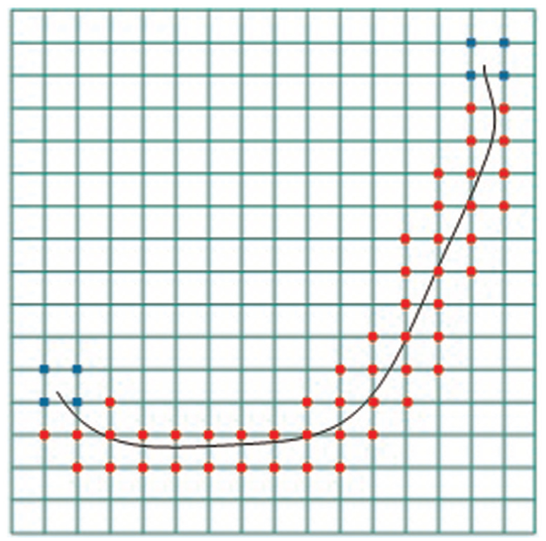
Node selection for topological enrichment.
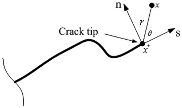
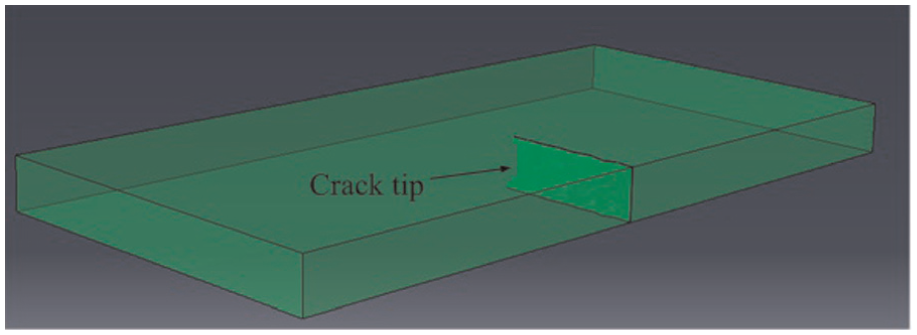
Specimen of coordinate system located at the crack tip.
The moving volumetric heat flux was used in this analysis, as shown in equation (5). The temperature field T (x, y, z, t) was obtained using a transient solution procedure governed by the following heat diffusion equation (6)
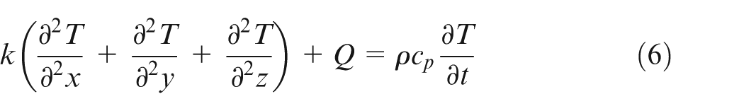
where k is the thermal conductivity,
A global coordinate system for the model has xy-plane as the scanning plane and z-axis as the thickness, as shown in Figure 5. For temperature test, the workpiece is positioned below the focal point and above the focal point, respectively. The parameters used for simulation with a moving heat source are summarized as follows: laser power P = 68 W, laser scanning speed v = 3.0 mm/s, laser beam diameter on the workpiece surface d = 3.0 mm and workpiece dimension 30 × 20 × 6.6 mm. For linear cutting experiment, the workpiece dimension 30 × 15 × 2 mm is positioned above the focal point. The initial temperature of the glass is set at T (x, y, z, t) = T0 = 20 °C. The boundary of the XFEM analysis is the fixed four vertices
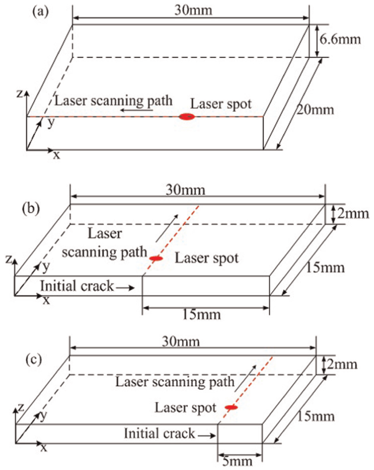
Specimen of coordinate system and geometric parameters for the model: (a) temperature experiments, (b) symmetric linear cutting glass with LITP and (c) asymmetric linear cutting glass with LITP.
Experimental procedure
Figure 6 shows the experimental apparatus for semiconductor laser cutting glass with LITP. The system is composed of a fiber optic–coupled semiconductor laser generator, an x–y–z positioning table, a fixture and a computer. The laser specifications are shown in Table 2. A thermal imaging camera was used to measure the temperatures. In the LITP, the defocused beam was used to induce and propagate the crack, to avoid melting and evaporation. The temperature gradient and external constraints generate the thermal stress to control the crack propagation. The real temperature distributions with a volumetric heat source must be obtained. The special fixture was designed.
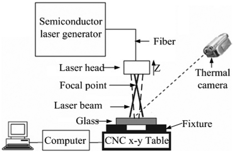
Schematic of the experimental apparatus for semiconductor laser cutting glass with LITP.
In the temperature experiments, the workpiece is positioned below the focal point and above the focal point, respectively; the laser optical axis is scanned along the edge to ensure that the half of laser is irradiated on the material, as shown in Figure 7. A thermal imaging camera was arranged as the same height as the material and perpendicular to the section of edge, which was used to measure the temperature along the thickness. In the cutting experiments, the material was positioned above the focal point. A diamond wire saw was used to make the initial crack more than 200 µm on the edge of the glass substrate. The glass sample used for cutting was soda-lime flat glass. Table 1 shows the physical properties of the soda-lime glass. The geometric parameters of the workpiece and laser scanning path are shown in Figure 5(b) and (c). The cutting parameters are the same as those used for simulation.
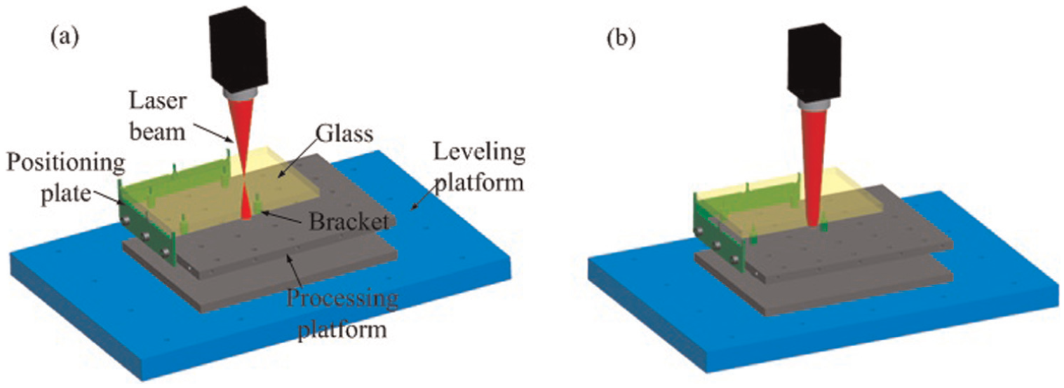
Schematic of the fixture and the temperature experiments: (a) below the laser focus and (b) above the laser focus.
Results and discussion
FE and temperature experiment results
In the LITP, the temperature distribution is one of the determinants for effective cutting and cutting quality. According to the cutting needs, the non-focused laser is used. Two suitable spots exist taking into account the characteristics of the laser focus. One suitable spot is above the laser focus and the other is below the laser focus.
Figure 8 shows the temperature distributions from the thermal imager and simulation. Figure 9 shows the graphs comparing the temperature along the thickness of the glass from the thermal imager and simulation. It can be seen that the simulation and experimental results are consistent. The temperature is decaying along the thickness of the glass. In the experiment with the heat source below the laser focus, the temperature drop in the thickness direction is about 75 °C, as shown in Figure 9(a). In the experiment with the heat source above the laser focus, the temperature drop in the thickness direction is about 38.5 °C, as shown in Figure 9(b). According to the results of the past studies, in laser cutting experiments, a small temperature drop is required along the thickness of the glass. So the heat source above the laser focus is the most favorable choice for processing.
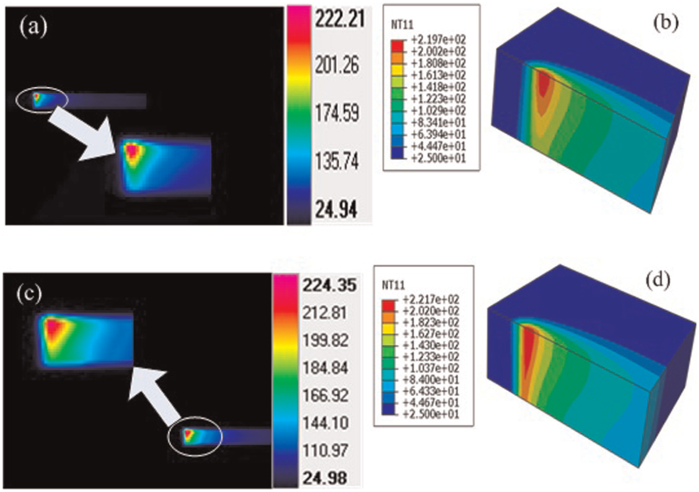
Temperature distributions of the temperature experiments: (a) temperature from the thermal imager below the laser focus, (b) temperature from the simulation below the laser focus, (c) temperature from the thermal imager above the laser focus and (d) temperature from the simulation above the laser focus.
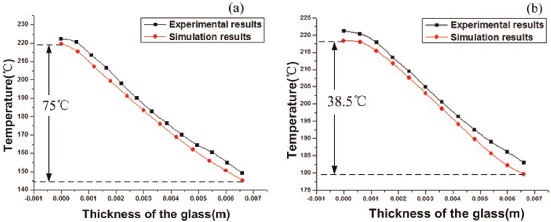
Graphs comparing the temperature along the thickness of the glass from the thermal imager and simulation: (a) below the laser focus and (b) above the laser focus.
FE and cutting experiment results
The temperature distributions of the symmetric and asymmetric cutting glass are shown in Figure 10. The maximum temperature does not melt the material at the laser spot. Figure 11 shows the graphs comparing the surface temperature vertical to the scanning path at the laser spot from the thermal imager and simulation. It can be seen that the simulation and experimental results are consistent.
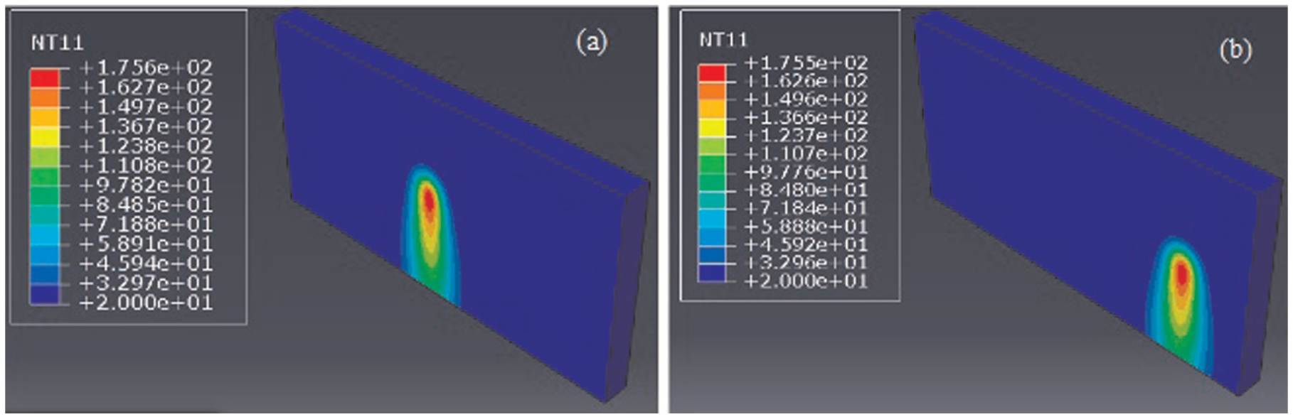
Temperature distributions of linear cutting glass with LITP: (a) symmetric cutting and (b) asymmetric cutting.
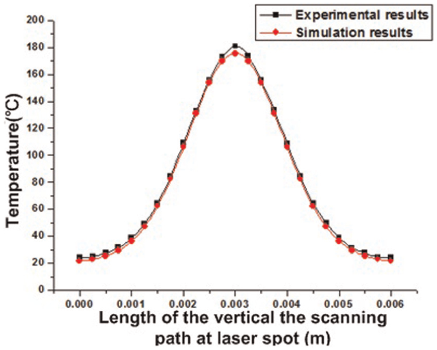
Graphs comparing the surface temperature from the thermal imager and simulation for symmetric cutting.
The stress distribution behind the laser beam is the tensile stress on the material surface and the compressive stress in the material interior, as shown in Figure 12. The crack propagation mode is from the material surface to the interior and the lower surface priority expansion, as shown in Figure 13. In the process of linear cutting with LITP, the material has an inhomogeneous distribution of temperature. The highest temperature appears at the laser spot. Because the surrounding material has a lower temperature, the free expansion of material is limited. The compressive stress appears at the laser irradiation area. With the laser left, the temperature reduces quickly. The temperature difference generates between behind the laser and the laser spot, the free shrinkage of the material behind the laser is limited and the tensile stress appears there. The material surface after laser scanning is affected by air convection, and the surface temperature decreases rapidly. Meanwhile, the inner material is only affected by heat transfer, and the inner temperature decreases slowly. The temperature difference on the surface is higher than that in the inner. As a result, the tensile stress is produced on the surface, and the compressive stress appears in the inner at the same time. With the process being carried out, the inner material temperature decreases, the compressive stress gradually becomes tensile stress and the crack propagates steadily from the surface to the interior.
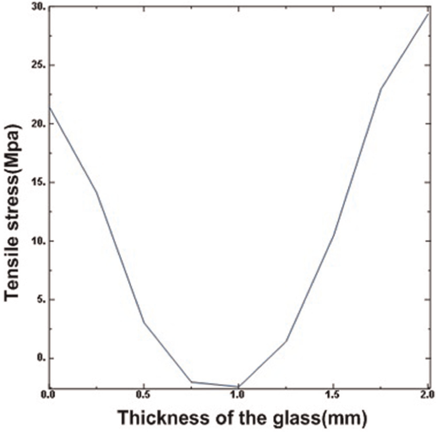
Stress distribution behind the laser beam along the thickness of the glass.
Crack propagation mode.
Figure 14 shows the crack sectional shape from the simulation results in linear cutting glass with LITP. In symmetric cutting, the crack sectional shape is flat. In asymmetric cutting, the crack sectional shape is sunk. According to the fracture mode-III, the crack sectional shape is determined by the shear stress parallel to the crack surface and perpendicular to the cutting direction. Figure 15 shows the shear stress along the thickness of the glass on the laser scan path. In symmetric cutting, the shear stress basically does not exist and does not affect the crack sectional shape. In asymmetric cutting, the shear stress and the tensile stress combined effect, as shown in Figure 16, makes the crack sectional shape sunk.
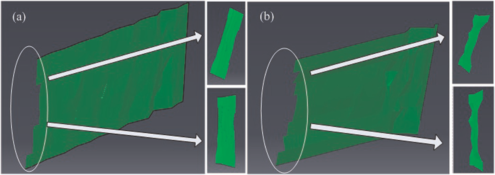
State of the crack surface from the simulation results: (a) symmetric cutting and (b) asymmetric cutting.
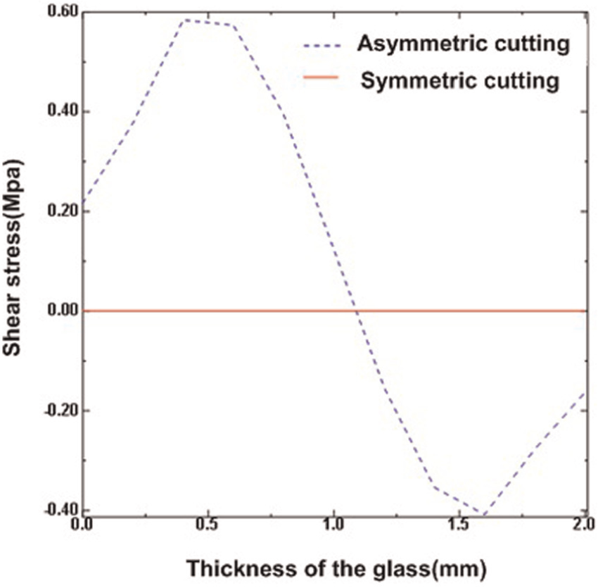
Shear stress along the thickness of the glass on the laser scan path.
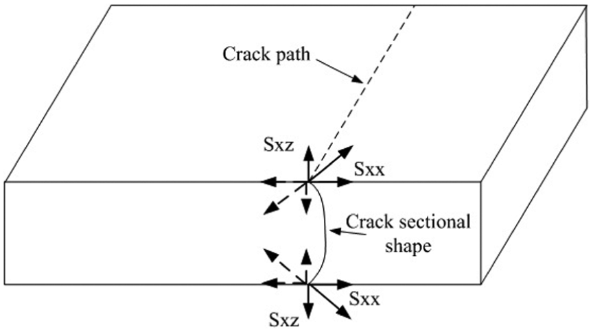
Combined effect of shear stress and the tensile stress.
Figure 17 shows the optical microscope photographs of the crack surface in linear cutting glass. The crack surface obtained by mechanical cutting has visible defects on the breaking surface edges as shown in Figure 17(a). These defects reduce the strength of the material and affect the subsequent processing. The crack surface obtained by LITP cutting has smooth and defect-free surface as shown in Figure 17(b) and (c). This surface effectively improves the yield of subsequent processing. Figure 18 shows the crack sectional shape from Carl Zeiss Stemi2000-C optical microscope in linear cutting glass with LITP. It can be seen that the crack sectional shape exhibits the same trend as the simulation results, as shown in Figure 14.
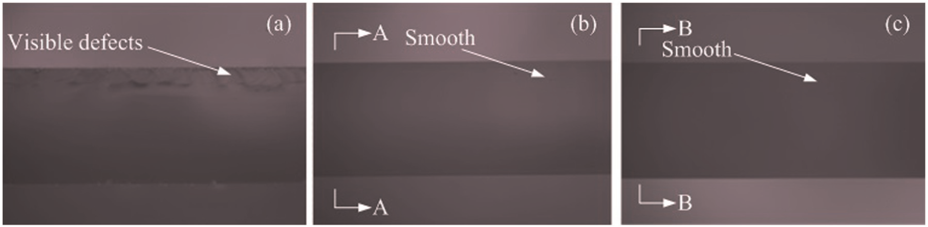
Optical microscope photographs of the crack surface in linear cutting glass: (a) mechanical cutting method, (b) symmetric cutting with LITP and (c) asymmetric cutting with LITP.
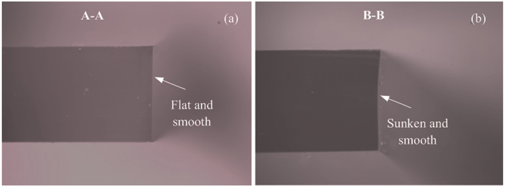
Crack sectional shape with LITP: (a) symmetric cutting and (b) asymmetric cutting.
Conclusion
The semiconductor laser (1064 nm), as a volumetric heat source, has been used for linear cutting glass with LITP. The crack surface quality is better than mechanical cutting. The driver for this study is more accurate to show the temperature distribution with focus position and to explain the mode of crack propagation and the crack sectional shape considering the dynamic extension of crack.
Considering the impacts of the laser divergence angle and heat source position, the volumetric heat flux formula is presented and used in simulation. The temperature experiment is carried out to prove the correctness of the theory and to find a more reasonable way of processing. It is found that the temperature is decaying and a small temperature drop is required along the thickness of the glass. The heat source above the laser focus is a more favorable choice for processing. The XFEM is used to simulate the crack propagation process and the crack sectional shape; the crack path does not have to be specified a priori. It is found that the crack propagation mode is from the material surface to the interior and the lower surface priority expansion. In symmetric cutting, the stress is almost perfectly symmetrical, it makes the crack linear expansion without the deviation and the shear stress basically does not exist to make the crack surface smooth and flat. In asymmetry cutting, shear stress is parallel to the crack surface and perpendicular to the cutting direction, which makes the crack surface smooth but uneven.
The results presented in this article are important for understanding the mode of crack propagation and the crack surface quality in linear cutting with LITP. However, more work is needed to study the appropriate way to improve the crack surface quality in laser asymmetry cutting glass.
Footnotes
Declaration of conflicting interests
The author(s) declared no potential conflicts of interest with respect to the research, authorship and/or publication of this article.
Funding
The author(s) disclosed receipt of the following financial support for the research, authorship, and/or publication of this article: This research was supported by China National 863 project (Grant No. 2015AA041902), China National 863 project (Grant No. 2012AA040210) and the National Natural Science Foundation of China (Grant No. 51275118); the authors gratefully acknowledge their support.