
Abstract
The machining systems that mainly consist of machine tools are numerous and are used in a wide range in industries. The total amount of energy consumption by machining systems in the world is extremely high. The loading loss energy is one of the most important and complicated parts of the energy consumption of machine tool in machining processes. The key of acquiring the loading loss energy is the acquisition of the loading loss coefficient, which is indispensable for machine tools’ energy efficiency on-line monitoring, energy prediction and energy quota customization. Up to now, the loading loss coefficient is mainly obtained by the experimental method which needs to conduct a large amount of experiments and a comprehensive on-line measurement to obtain the input power, idle power and cutting power beforehand. On the other hand, in many cases, it is unavailable to install the dynamometers on the machine tool’s worktable to measure the parameters on-line. This article provides a mapping method to acquire the loading loss coefficient of main driving system of machine tools. First, choose a standard machine tool, cutter and workpiece to construct the standard machining circumstance. Second, carry out the experiments with a series of given cutting parameters under the standard circumstance and record the cutting power accordingly. Third, construct the overall cutting power model which can be used to calculate the cutting power of any other target machine tools under the standard machining circumstance. Fourth, establish the air-cutting power database of the target machine tools. Then, carry out the experiments on the target machine tool with the parameters which is as close as possible to the standard parameters and record the input power of the main driving system respectively. Finally, substitute the input power, air-cutting power and cutting power into the acquisition model to calculate the loading loss coefficient. The case study indicates that this method with high accuracy, on the other hand, can simplify the procedure of the acquisition of the loading loss coefficient to a great degree and shows that the method is practical and promising.
Introduction
The machining systems that mainly consist of machine tools are numerous and are used in a wide range in industries. The total amount of energy consumption by machining systems in the world is extremely high. Many preliminary studies have indicated that more than 99% of the environmental impact of manufacturing is a result of their energy consumption levels. 1 And it is also reported that the energy use in manufacturing industry contributed to 37% of the world’s total energy consumption. 2 As a result, sustainability manufacturing is nowadays a wide research field due to the urgency of reducing environmental burdens of industrial production. 3 The key of the sustainability manufacturing is to reduce the energy consumption of machine tools for machining processes, and the first step toward reducing energy consumption in machine tools or manufacturing systems is to understand and characterize their energy consumption. 4
Lau et al. 5 proposed an energy consumption change forecasting system using fuzzy logic to reduce the uncertainty, inconvenience and inefficiency resulting from variations in the production factors. Pervaiz et al. 6 proposed an approach for the prediction of energy consumption and related environmental implications using finite element modeling simulations. Elias et al. 7 indicated that there are two kinds of losses: intrinsic losses and user-related losses, and set out a theoretical framework for understanding and calculating the intrinsic losses and user-related losses of products. Draganescu et al. 8 used experimental data and response surface methodology (RSM) to establish a statistic model of machine tool efficiency and specific energy consumption in machining. Li and Kara 9 have developed a method to predict the total energy consumption of a selected machine tool performing a turning operation. Arif et al. 10 have presented a model for the optimization of machining parameters for the minimum energy consumption in a multi-pass turning operation. Kara and Li 11 presented an empirical model to characterize the relationship between energy consumption and process variables for material removal processes. Avram and Xirouchakis 12 evaluated the use phase energy requirements of a machine tool system by considering alternative machining strategies and system component interactions. Ding et al. 13 developed an integrated modeling methodology to quantify the energy consumption and equivalent carbon footprint in the grinding process. He et al. 14 proposed a practical method for estimating the energy consumption of numerical control (NC) machining. Nevertheless, in their researches, the loading loss of spindle system has not been taken into consideration, which accounts for 15%–20% of the cutting power 15 and may be up to 30% of the cutting power in practical measurement. 16 In recent years, many significant research studies on the loading loss have been performed.
According to Chaudhari 17 and Saidur, 18 the additional losses of induction motor included the stator winding losses, rotor losses and stray load losses. Liu et al. 15 indicated that the loading loss of mechanical transmission was proportional to the load. However, there is still a lack of mathematical method for calculating the loading loss of machine tools because there are so many parameters of spindle system and some of which are difficult to obtain. Liu et al. 15 indicated that the loading loss was proportional to the cutting power. Shi 19 established an energy flow model of spindle system which was driven by variable-voltage-variable-frequency (VVVF) inverter and analyzed the loading loss on each part of the spindle system in the computer numerical control (CNC) machine tools. They all treated that the loading loss coefficient (LLC) was a constant; however, the conclusion only works on a specific frequency. Hu et al. 16 have analyzed the characteristics of the loading loss power and established an experimental system to measure the LLC of the machine tool; however, the coefficients of the models are difficult to obtain. Liu et al. 20 fitted the LLC based on the measurement of cutting power and the main driving system input power. The method is very complicated, which needs to conduct a large amount of experiments and a comprehensive on-line measure to obtain the input power, idle power and cutting power beforehand. While in many cases, the dimension or structure limits of some machine tools, it is unavailable to install the dynamometers to measure the parameters.
To resolve this dilemma, this article proposed a mapping method to acquire the LLC. The method can simplify the experiment processes to a great degree and make the on-line measurement more practical. This method is capable of providing support for the analysis of energy consumption, the estimation of energy efficiency and the energy consumption prediction of machine tools in machining processes.
General idea and model for acquiring the LLC
For the method to acquire the LLC of machine tools, the standard machining circumstance is essential, which includes the standard machine tool, cutter, workpiece and cutting parameters. First, Choose a machine tool and carry out the experiments under the standard circumstance to construct an overall cutting power model of the cutting system. Mapping the experimental circumstance to any other target machine tools, the cutting power can be obtained conveniently. Then, construct the air-cutting power for all the target machine tools beforehand for the acquisition of the LLC. Finally, measure the input power of the main driving system of the target machine tools in the standard machining processes, so that the LLC can be obtained by the acquisition model
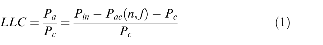
where
Acquisition of the overall cutting power model
Design of the standard part and parameters
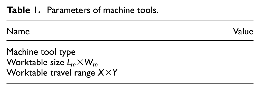
The standard workpiece and cutting parameters are the basis for acquiring the overall cutting power model. They are the bridge between the standard machine tool and the other target machine tools. The standard workpiece should be designed according to the standard machine tool, especially for the size and the travel range of the worktable. Use

Use

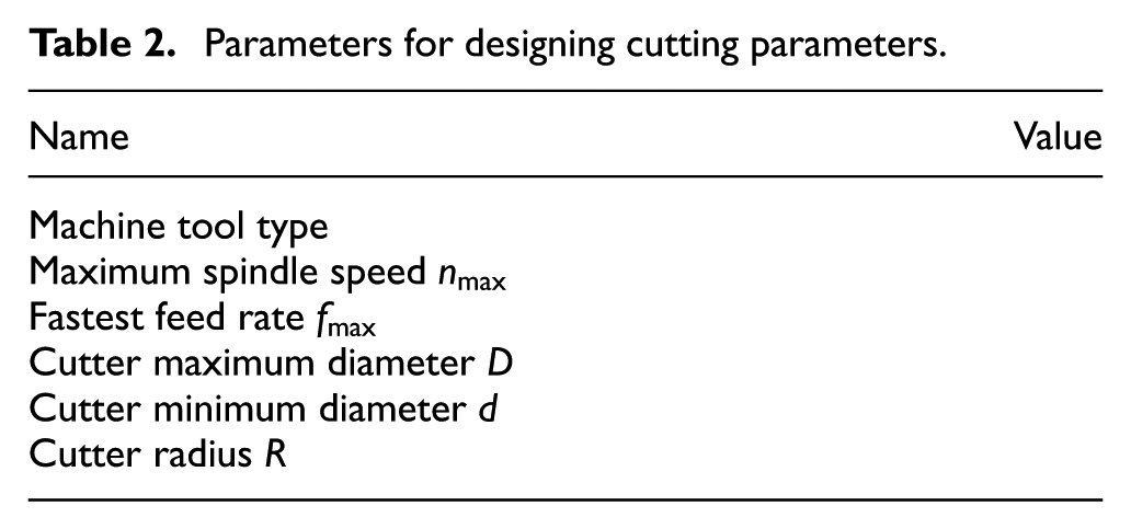
When designing the standard cutting parameters, it is necessary to take the capacity of the machine tools into consideration. So, the spindle speed and the feet rate of the standard cutting parameters ought to satisfy

where
Parameters of machine tools.
Likewise, the design of standard cutting parameters is according to
Parameters for designing cutting parameters.
When the cutter and standard workpiece are settled, cutting power is only influenced by the three cutting parameters: cutting speed, feed rate and cutting depth. As a result, the machining experiments to obtain the overall cutting power model is set as a
Overall cutting power model of cutting system
The orthogonal experiments are carried out under the standard circumstance and the cutting force is measured respectively. Based on those data and with the help of numerical integration, the cutting power value of each group of cutting parameters is acquired. Taking milling machine as an example, the computing model is as follows
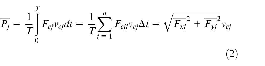
while


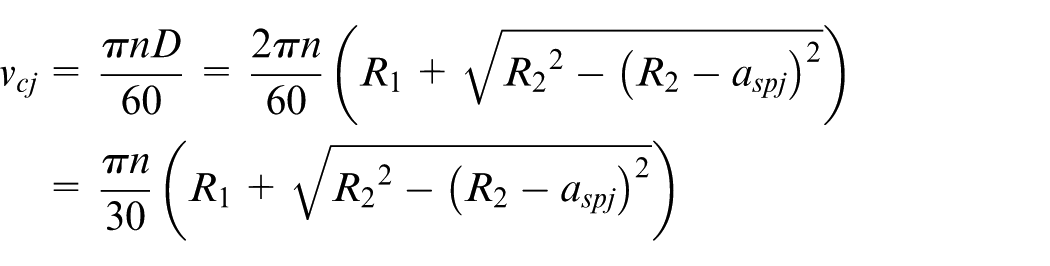
where
If the cutting parameter group includes three cutting parameters, the spindle speed
The three-parameter model

The four-parameter model

Taking the four-parameter model as an example, the model can be changed into model (5)
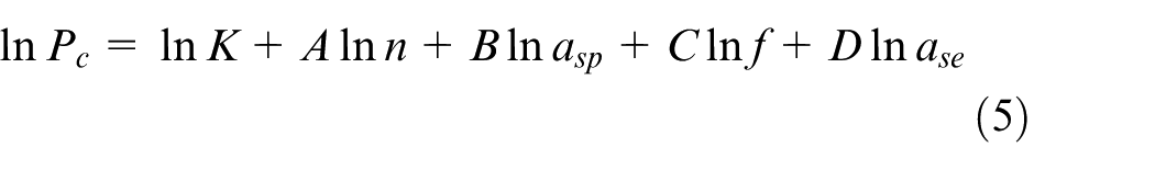
where

Residual sum of squares is
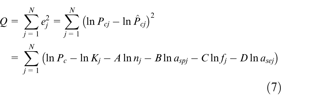
To minimize the residual sum of squares, the following conditions should be satisfied
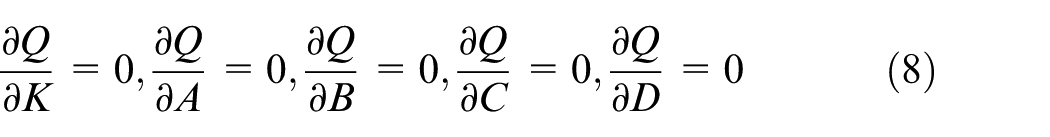
In the end, fitting the results of equation (8), the model constants
Air-cutting power model of the target machine tools
According to the acquisition model, to calculate the LLC, the acquisition of air-cutting power is essential. The air-cutting power varies to the spindle speed and feed rate. However, when the spindle speed and the feed rate is certain, the air-cutting power is constant, which means that there is a functional relationship between the air-cutting power and the spindle speed and feed rate. As a result, the fitting function of the spindle speed and feed rate can be used to calculate the air-cutting power. According to the types of machine tools, models for air-cutting power have two different forms:
(a) Air-cutting power is approximately a quadratic function to the spindle speed and a linear function to the feed rate. In this condition, the air-cutting model can be fitted as follows
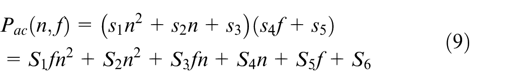
where
(b) When the law of the air-cutting power varies with the basic frequency, the air-cutting power model can express a segment function to spindle speed and still a linear function to feed rate. The fitting model is as follows
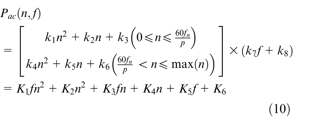
In this model,
Procedure of the acquisition method of the LLC
In conclusion, the general procedure to acquire the LLC is as follows.
First, choose a standard machine tool, cutter and workpiece to construct the standard machining circumstance. Second, carry out the experiments with a series of given cutting parameters under the standard circumstance and record the cutting power accordingly. Third, construct the overall cutting power model which can be used to calculate the cutting power of any other target machine tools under the standard machining circumstance. Fourth, establish the air-cutting power database of the target machine tools. Then, carry out the experiments on the target machine tool with the parameters which is as close as possible to the standard parameters and record the input power of the main driving system respectively. Finally, substituting the cutting parameters into the overall cutting power model and the air-cutting power, the corresponding results can be easily obtained. Up to now, the cutting power, air-cutting power and the input power are all ready; the LLC is easily obtained by the acquiring model (1). The procedures are illustrated in Figure 1.
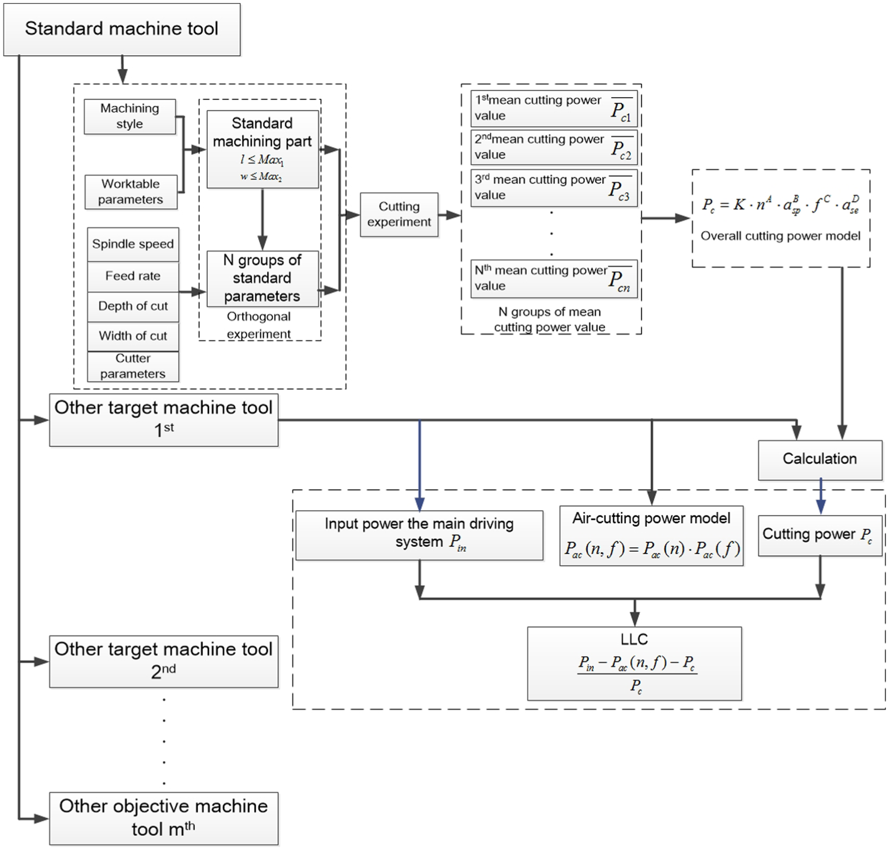
General procedure to acquire the LLC.
Case study
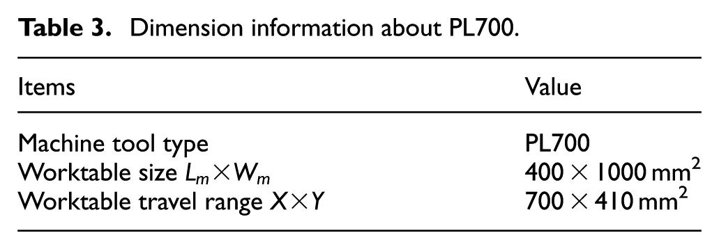
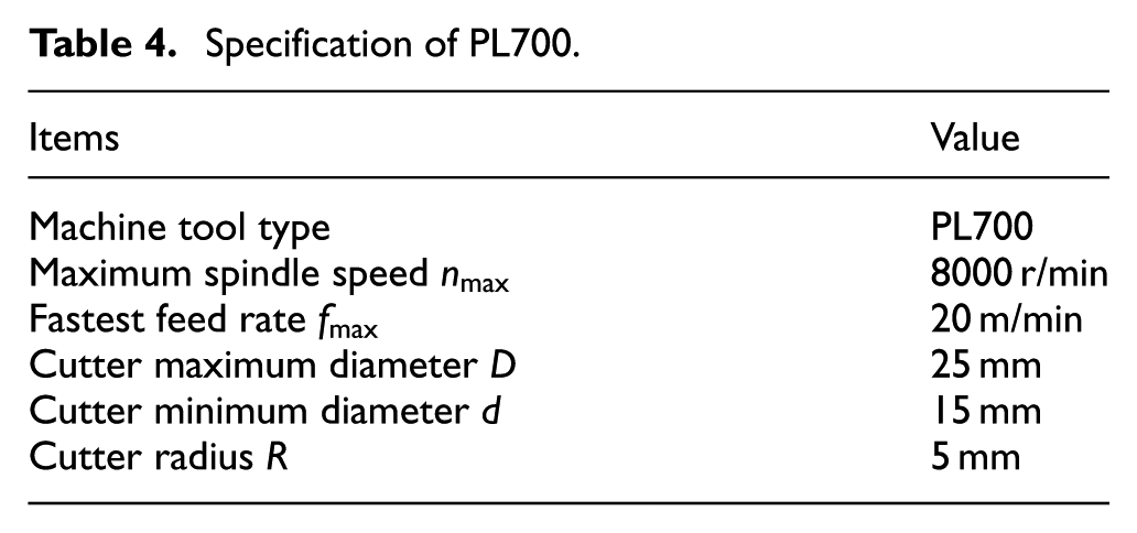
The case study choose the machining center PL700 as the standard machine tool and the vertical machining center HASS VF-5/50TR as the target machine tool. So, the standard overall cutting power model should be constructed on PL700, and it can be used to calculate the LLC of HASS VF-5/50TR. The parameters of PL700 are listed in Tables 3 and 4.
Dimension information about PL700.
Specification of PL700.
Design of the standard part and parameters
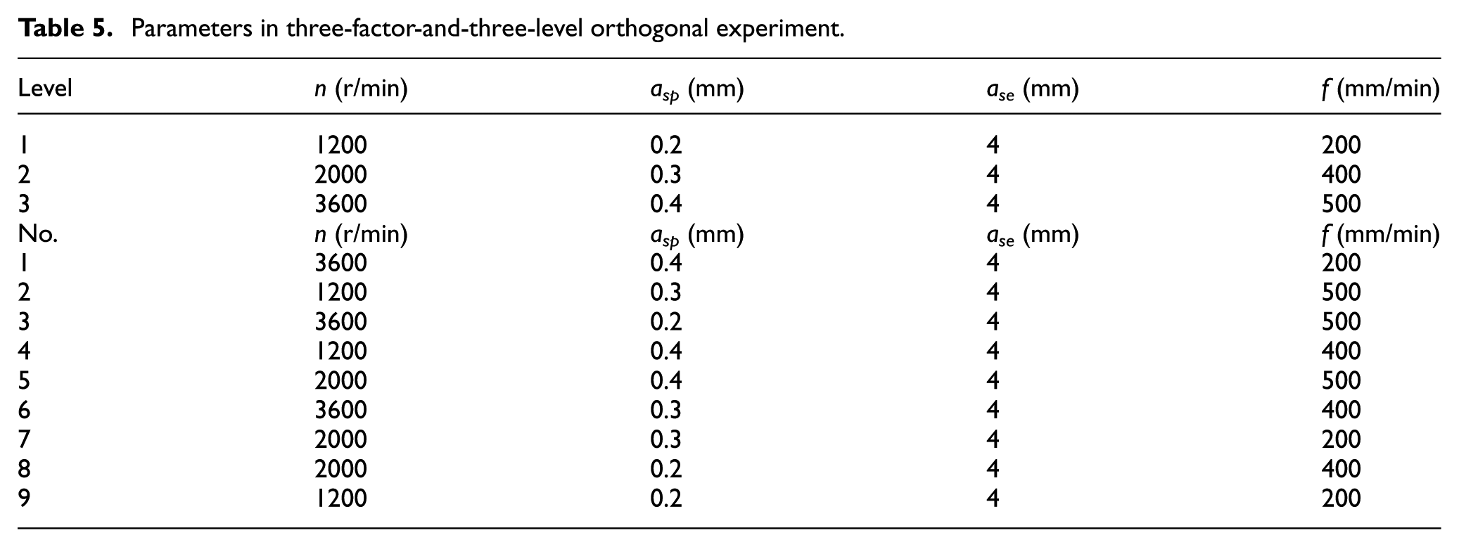
Choose a 45-mm steel plate in 170 × 100 × 29 mm3 (shown in Figure 2) as the standard workpiece. It is designed according to the requirements introduced in section “General idea and model for acquiring the LLC.” The cemented carbide (coated) cutter (RPEW1003MO HP7025) is chosen to conduct the experiments. The maximum diameter of the cutter is 25 mm while the minimum is 15 mm. The Kistler 9257B dynamometer, 5670A data acquisition system and 5070 charge amplifier were chosen to constitute the force measuring system. The HIOKI power analyzer 3390 with 0.05 s sampling interval is applied to measure the input power. Milling of the workpiece was performed along a straight line with three levels of cutting speed, depth of cut and feed rate, and the width of cut
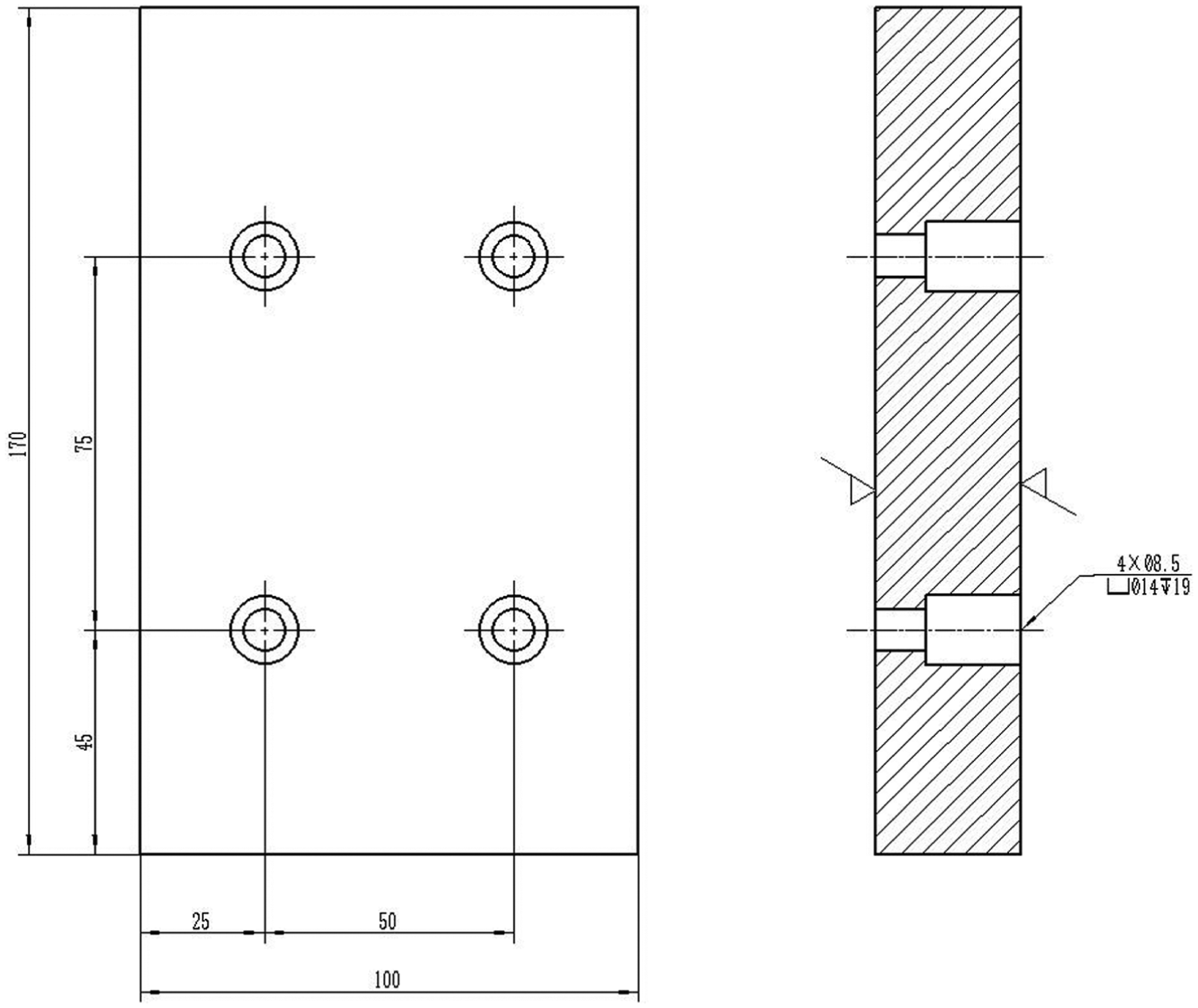
Standard workpiece for milling machine tools.
Parameters in three-factor-and-three-level orthogonal experiment.
Acquisition of overall cutting power model
Applying the parameters to cut the standard part on PL700, a group of cutting power values can be measured (Table 6).
Cutting power measured on PL700.
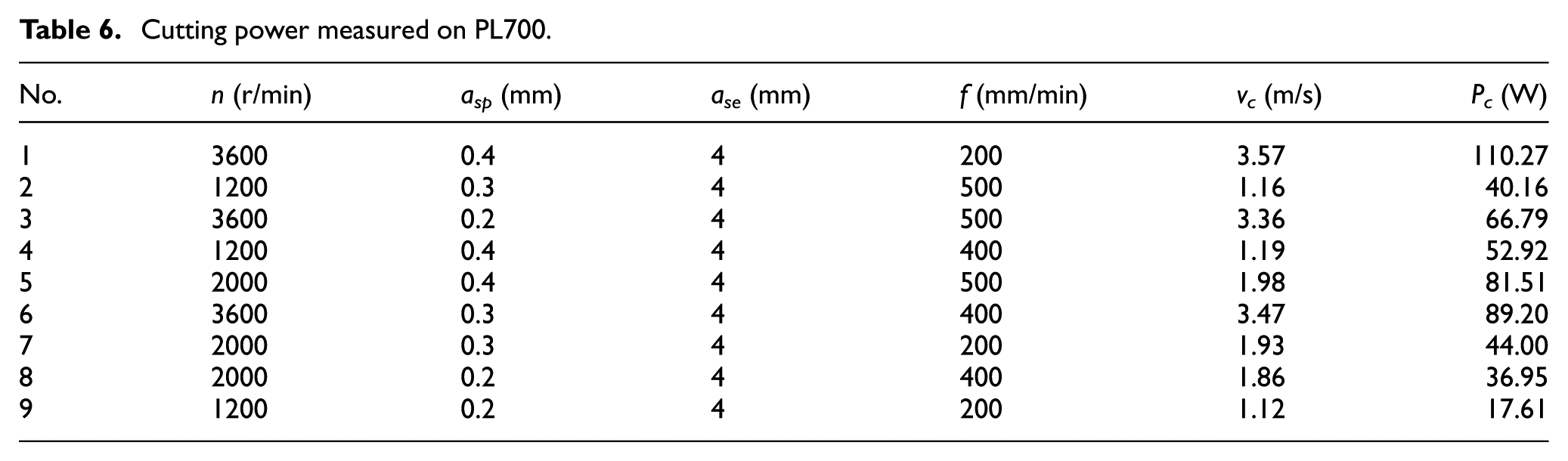
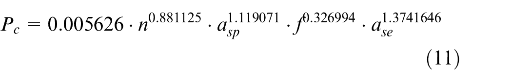
According to the experimental results, the overall cutting power can be fitted as follows
(a) Acquisition of the air-cutting power of HASS VF-5/50TR
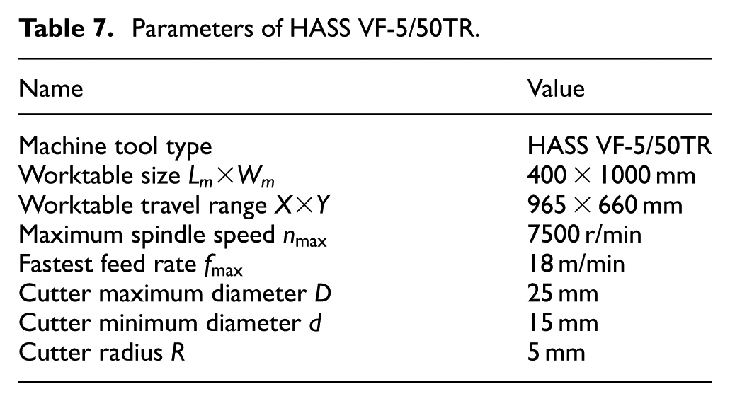
Details of HASS VF-5/50TR are listed in Table 7. To establish the air-cutting power database, the experiment is designed based on machine tool parameters (Table 7). The spindle speed and feed rate in this experiment are 200–5000 r/min and 100–700 mm/min, respectively. Basic frequency for this machine is 60 Hz and the number of pole pairs of the motor is 2.
Parameters of HASS VF-5/50TR.
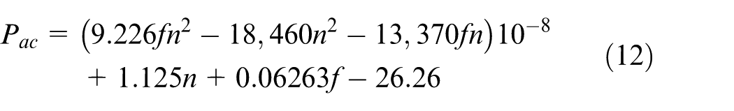
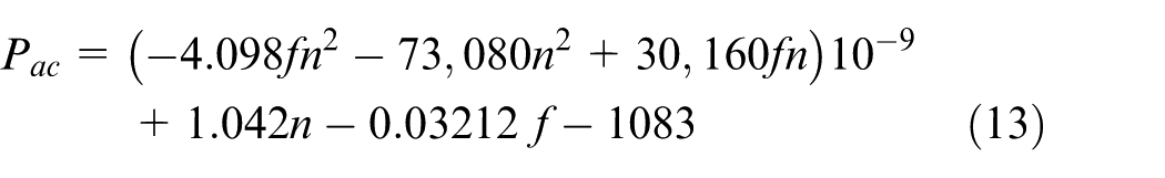
Air-cutting models for HASS VF-5/50TR
When
When
(b) Acquisition of cutting power and the LLC of HASS
When the standard parameters are available to the target machine tools, the LLC can be calculated without the error which is caused by the calculation. To demonstrate this situation, the validation is conducted and the results are listed in Table 8.
Cutting power of HASS according to the LLC of standard cutting parameters.
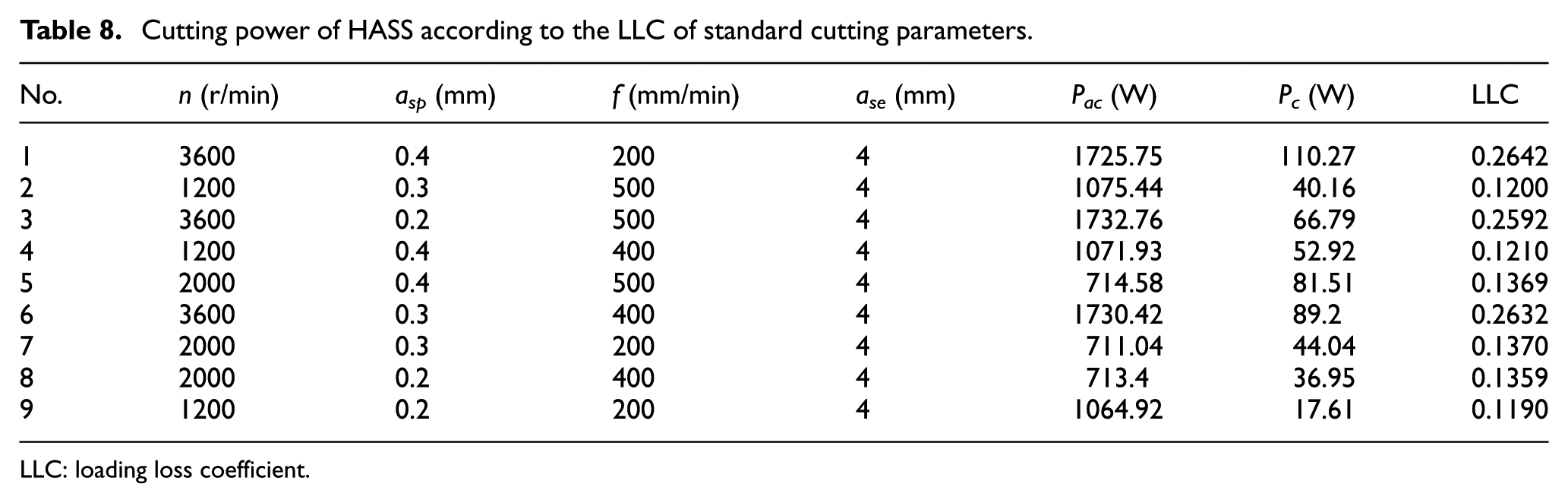
LLC: loading loss coefficient.
If the standard parameters are unavailable to the target machine tools, there may be some errors which are caused by the calculation. In this case, the results are listed in Table 9.
Experimental parameters and results.
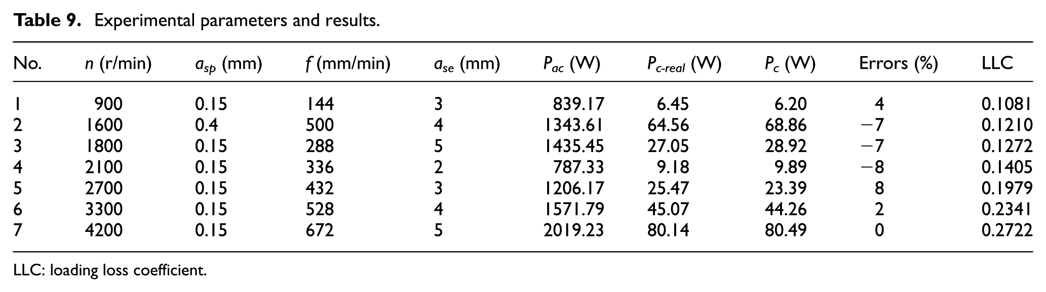
LLC: loading loss coefficient.
In Table 9, the errors between the measuring cutting power and computing cutting power by the overall cutting power model varies within the range of ±8%, which implies that the overall cutting power model has a high accuracy. Furthermore, once the overall cutting power model is constructed, the LLC can be easily acquired by the method proposed in this article. What’s more, from Tables 8 and 9, the LLC may reach up to 0.26, it implies that the loading loss power usually accounts for a rather high proportion, which cannot be neglected. Hence, it is of great significance to study the LLC of the main driving system.
Conclusion
The loading loss energy is one of the most important and complicated parts of the energy consumption of machine tool in machining processes. The key to the acquisition of the loading loss energy is the acquisition of the LLC which is indispensable for machine tools’ energy efficiency on-line monitoring, energy prediction and energy quota customization. Up to now, the LLC is mainly obtained by the method which needs to conduct a large amount of experiments and a comprehensive on-line measurement to obtain the input power, idle power and cutting power. On the other hand, in many cases, it is unavailable to install the dynamometers on the machine tool’s worktable to measure the parameters on-line. This article provides a mapping method to acquire the LLC of main driving system of machine tools. First, a machine tool needs to be chosen as a standard machine tool which is available to install the dynamometer. Following designing, the standard cutting conditions are based on machine’s capacity and constructing experiments under the standard cutting circumstance. Then, constructing the overall cutting power model is based on the results of the experiments. Successively, an air-cutting power database of the target machine tools is established, and the input power of the main driving system under the standard machining circumstance is measured accordingly. Eventually, all those power data are substituted into the LLC acquiring model, so that the LLC of the target machine tools can be obtained.
The case study indicated that the method overcomes the drawbacks of the installation of measuring equipment and can simplify the whole procedure of the acquisition of the LLC to a great degree. The results show that the method is practical and feasible. The method has good prospect for providing support to the further research of the overall energy consumption of machine tools, energy quota and the improvement of energy efficiency.
Footnotes
Declaration of Conflicting Interests
The author(s) declared no potential conflicts of interest with respect to the research, authorship and/or publication of this article.
Funding
The author(s) disclosed receipt of the following financial support for the research, authorship, and/or publication of this article: This work was supported by the National Natural Science Foundation of China (grant no. 51375513) and the Specialized Research Fund for the Doctoral Program of Higher Education (grant no. 20120191110001).