
Abstract
This study seeks to develop an efficient way of quantitatively investigating the intrinsic size effect in machining. This is accomplished by carrying out the following procedures: conducting the pure two-dimensional orthogonal machining with the cutting edge radius and the uncut chip thickness varied, investigating the relation between the cutting edge radius and the specific cutting energy when the uncut chip thickness is fixed, and then estimating the specific cutting energy for a perfectly sharp tool by extrapolating the relations obtained for different values of the uncut chip thickness. Finally, the usefulness of the developed method is validated by showing that the estimate of the specific cutting energy for a perfectly sharp tool can be effectively utilized for understanding and modeling the intrinsic size effect, especially the material length scale, in machining.
Keywords
Introduction
The size effect in machining is known to be the phenomenon that resistance for cutting, or specific cutting energy, increases nonlinearly as the uncut chip thickness is decreased.
1
This size effect is more salient in micro-machining where the uncut chip thickness is in the order of µm
The size effect in machining can be classified into two types by the nature of its causes. The first type is associated with the geometric imperfection of cutting edge that is either naturally or intentionally introduced in the fabricating process of cutting tools. 4 In reality, no tool has a perfectly sharp cutting edge but an edge with a finite radius. 5 Therefore, the cutting geometry represented by the ratio between the uncut chip thickness and the cutting edge radius (immersion ratio) is varied as the uncut chip thickness is varied.6–9 That is, the effective rake angle becomes more negative as the uncut chip thickness is decreased while the cutting edge radius is fixed. Under this condition, the shear plane angle decreases and the relative contribution of material plowing increases. Consequently, the energy dissipated for the material removal—specific cutting energy is increased. When decoupled from the other type of size effect, this type is called “geometric” size effect because it is caused by solely the geometric reason as explained above.
The second type is associated with the phenomenon that material strength increases as the length scale of material deformed (i.e. the uncut chip thickness in machining) is reduced. Since such strengthening of material is considered as an intrinsic property of material, this type of size effect is called “intrinsic” size effect. The intrinsic size effect has been of great interest to many researchers, and many attempts have been made to understand its mechanism. Among them, noticing the defects existing in or between the crystals such as missing atoms, impurities, grain boundaries and so on, Backer et al. 10 claimed that the material strength gradually increases and thus approaches the theoretical strength because the likelihood of encountering such defects in the volume deformed would be decreased with the decrease of uncut chip thickness. Kopalinsky and colleagues11,12 claimed that the decrease in the tool–chip interface temperature would strengthen the material as the uncut chip thickness is decreased. Dinesh et al. 13 introduced the strain-gradient theory to machining, which had been successfully employed to explain the size effect for other processes involving the plastic deformation of material.14–17 The strain-gradient theory states that the increase of strain gradient which would occur when the uncut chip thickness is reduced in machining would increase the geometrically necessary dislocations and thus strengthen materials. 18
Although many attempts have been made to explain the intrinsic size effect in machining, it should be noted that there have been few efforts to verify its models quantitatively. This is associated with the fact that in reality, cutting tools are not perfectly sharp and thus it is not easy to investigate the intrinsic size effect separately from the geometric size effect through cutting experiments. To minimize the geometric size effect, the ultra-precision cutting with a diamond tool which has a very sharp cutting edge (radius < 100 nm) is often employed. 19 However, in many cases, this is not practical because slight wear on the cutting edge would mislead the results. Especially, diamond tools are not suitable for cutting of ferrous materials because the carbon comprising diamond diffuses into the materials, which substantially accelerates the tool wear during machining.
In this regard, this study aims at developing an efficient way of quantitatively investigating the intrinsic size effect in machining without using the ultra-precision cutting. This will be accomplished by taking the following procedures. First, the pure two-dimensional (2D) orthogonal machining will be performed by varying the cutting edge radius and the uncut chip thickness (section “Experimental details”). Second, the relation between the cutting edge radius and the specific cutting energy when the uncut chip thickness is fixed will be investigated by analyzing the cutting force data. Then, the specific cutting energy for a perfectly sharp tool will be estimated by extrapolating the relations obtained for different values of the uncut chip thickness (section “Results and analysis”). Finally, the usefulness of the developed method will be validated by showing that the estimate of the specific cutting energy for a perfectly sharp tool can be effectively utilized for understanding and modeling the size effect, especially the material length scale, in machining (section “Application and discussion”).
Experimental details
Pure 2D orthogonal machining configuration
The pure 2D orthogonal machining has been widely used for fundamental studies of machining because the chip formation process can be represented in a 2D plane. In this study, the pure 2D orthogonal machining was realized by a setup consisting of a linear slide and a precision stage as seen in Figure 1. In this setup, the cutting tool was held stationary and the workpiece was moved perpendicular to the cutting edge by a ball-screw driven linear slider (maximum speed: 1000 mm/s). The cutting tool was fixed onto a tool dynamometer (Kistler 9257B) for the force measurement during cutting. The assembly of the cutting tool and the tool dynamometer was mounted onto a precision stage with a digital micrometer that had a resolution of 1 µm over a range of 20 mm. The uncut chip thickness could be accurately set based on the readings from this digital micrometer. The precision stage was fixed onto a cast iron column. On the other hand, the workpiece was mounted on the linear slider.
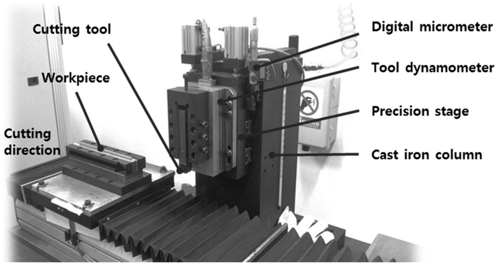
Pure two-dimensional (2D) orthogonal cutting arrangement.
Cutting conditions
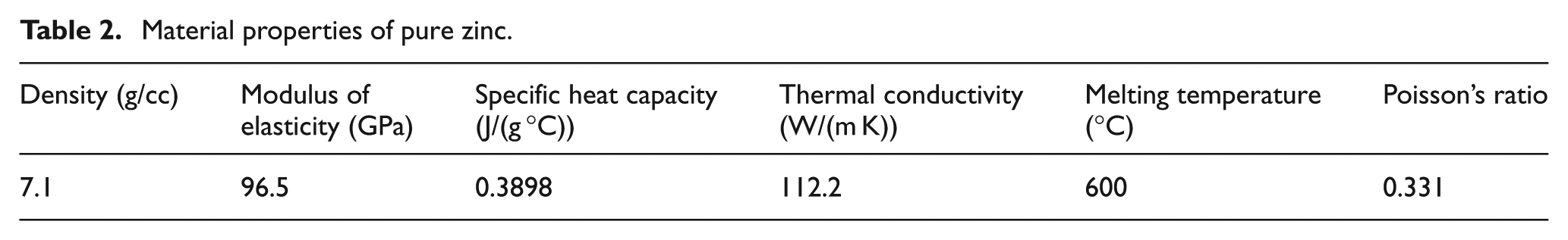
For work material, pure zinc was chosen for its good machinability and comparison with the relevant previous studies. The material was used in the form of plate (size: 100 mm (width) × 50 mm (height) × 1.5 mm (thickness)) as received (purity: 99.95%, temper: as rolled, manufacturer: Goodfellow). The use of thin plates for the workpiece ensured plane strain or 2D deformation for each of the cuts.
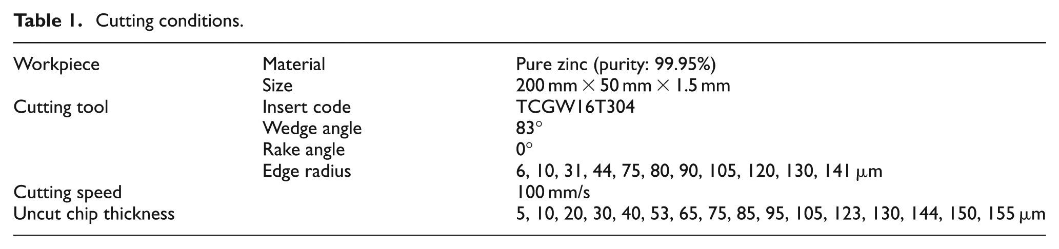
For cutting tools, uncoated turning inserts made of tungsten carbide were used. The inserts had the triangular shape, wedge angle of 83° and inscribed circle radius of 9.525 mm (model no.: TCGW16T304; manufacturer: KORLOY Inc.). The rake angle and clearance angle were 0° and 7°, respectively, when the inserts were set with a screw onto the tool holder (model no.: STFCR2020-K16; manufacturer: KORLOY Inc.). The edge radii of the inserts were varied in the range of 6–141 µm as shown in Table 1.
Cutting conditions.
The cutting edge radius was determined by measuring the cutting edge profile using a contour profiler (TELSTAR-HOMMEL T8000) and finding a circle which meets the condition as suggested by Ahn et al. 20 —it should be best fitted onto the cutting edge profile while its center should be placed on the bisectional line of the wedge angle. An example of the cutting edge profile and the schematic of determining the edge radius are displayed in Figure 2.
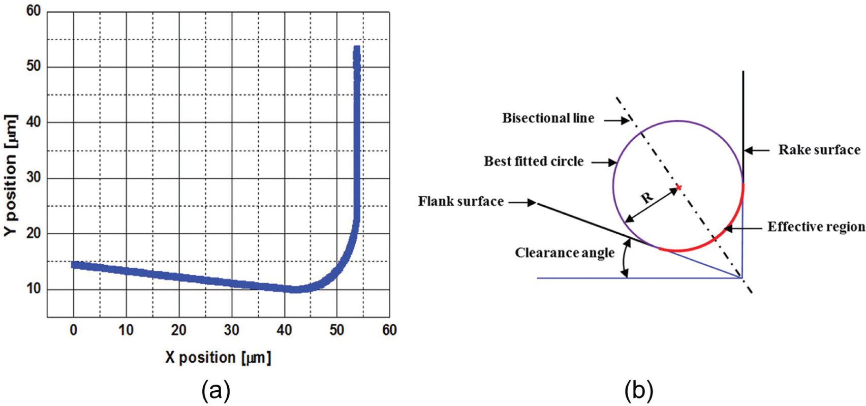
(a) An example of cutting edge profile measured and (b) schematic of determining the edge radius.
Cutting was carried out dry at the low speed of 100 mm/s to minimize the effect of temperature rise in the workpiece during machining. When measured by applying the infra-red (IR) thermography, 21 the temperature rise in the deformation zone was found to be less than 30°C (see Figure 3 for an example). It is assumed that such a low temperature rise would not affect the material strength.
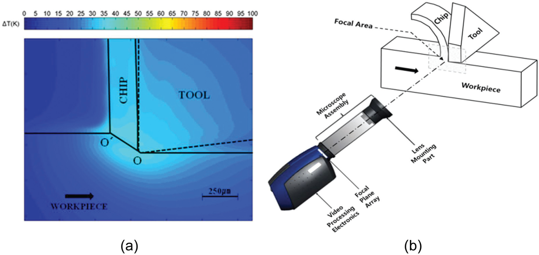
(a) Temperature field in the workpiece measured and (b) schematic showing the infra-red (IR) imaging system used for the measurement.
In the meantime, the uncut chip thickness was varied within a range depending on the cutting edge radius. The lower boundary of the range was not smaller than 0.2 times of the cutting edge radius, below which the chip was not formed stably. The upper boundary was fixed at 155 µm. For each of the combinations of cutting edge radius and uncut chip thickness, cutting was repeated five times for the statistical analysis of the data. The cutting conditions as described above are summarized in Table 1.
Results and analysis
Relation between the specific coefficients and the cutting edge radius
Figure 4 shows the variation of cutting forces and specific coefficients as the cutting edge radius is varied. These plots were obtained by conducting the pure 2D orthogonal machining of pure zinc with variation of the cutting edge radius (6–141 µm) while the uncut chip thickness was fixed at 155 µm. The cutting forces were directly measured from the tool dynamometer during machining, and the specific coefficients were calculated by dividing the cutting forces by the uncut chip area (uncut chip thickness × uncut chip width). As a result, the plots for the cutting forces and the specific coefficients versus the cutting edge radius show the same trend. Here, it should be noted that “the specific coefficient in cutting direction” corresponds to “the specific cutting energy.” Also, the values of cutting forces and specific coefficients in these plots are those averaged over five repeated cuts.
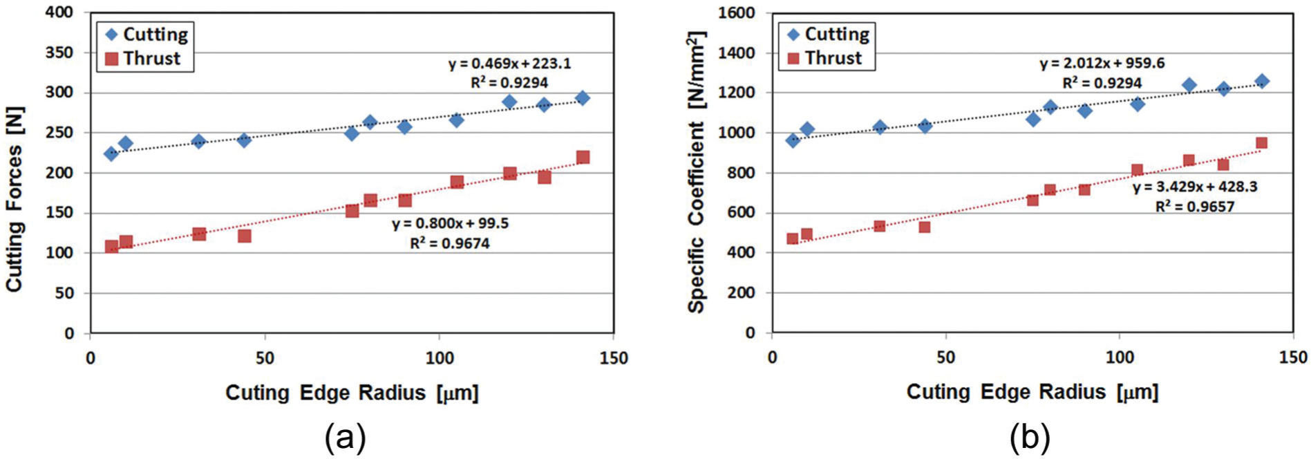
Relation of (a) cutting forces and (b) specific coefficients with cutting edge radius (uncut chip thickness: 155 µm).
In these plots, it is worthwhile to note that the specific coefficients monotonically increase with the increase of the cutting edge radius and the correlation is high for both coefficients. It is also interesting to note that the slope of the fitting line for the thrust component is stiffer than that for the cutting component and the correlation for the thrust component (R2 = 0.9657) is higher than that for the cutting component (R2 = 0.9294). This is commonly found for all the plots made in the same way with various uncut chip thickness. That is, the effect of cutting edge radius is more salient in the thrust component than in the cutting component. This indicates that it may be better to investigate the thrust component rather than the cutting component to see the effect of cutting edge radius more clearly.
Estimation of the specific coefficients for a tool with a perfectly sharp cutting edge
Such good correlation between the specific coefficients and the cutting edge radius as evidenced in Figure 4 indicates that the specific coefficients for the perfectly sharp cutting edge could be reliably estimated by extrapolating the fitting curves and reading the abscissa in the y-axis. These are found to be 959.6 N/mm2 for the cutting component and 428.3 N/mm2 for the thrust component in Figure 4. The estimates of the specific coefficients when cutting with the perfectly sharp cutting edge for various uncut chip thickness could be obtained by applying this method to the figures made for various uncut chip thickness. The results are shown in Figure 5.
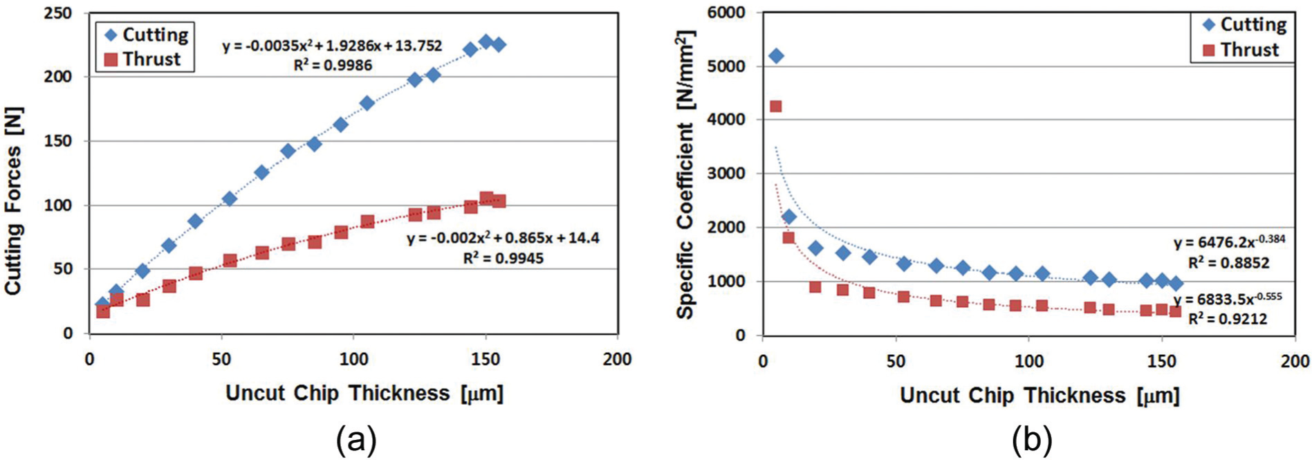
Estimates of (a) cutting forces and (b) specific coefficients when cutting with a perfectly sharp cutting edge for various uncut chip thickness.
In Figure 5(a), the estimates of the cutting forces for a perfectly sharp cutting edge monotonically increase with the increase of the uncut chip thickness. The correlations between the cutting forces and the uncut chip thickness are very high when they are related in the quadratic form (R2 = 0.9986 and 0. 9945 for the cutting and thrust components, respectively). On the other hand, Figure 5(b) shows the size effect in which the specific coefficients exponentially increase as the uncut chip thickness decreases. However, here, only the intrinsic size effect is present because the specific coefficients were estimated for a perfectly sharp cutting edge and thus the geometric size effect was excluded. Therefore, Figure 5(b) can be effectively utilized for understanding and modeling the intrinsic size effect in machining as will be shown in the next section.
Application and discussion
Material length scale
Since Dinesh et al.
13
introduced the strain-gradient theory to machining, many researchers have applied it for modeling of machining processes.19,22–25 When the Taylor-based nonlocal theory of plasticity
26
is employed to explain the strain-gradient theory, the flow stress (
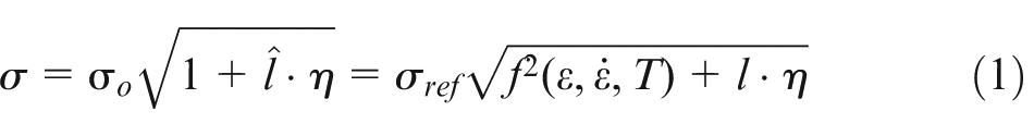
Here,
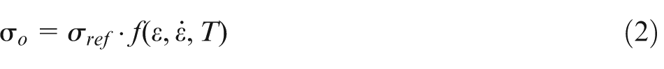
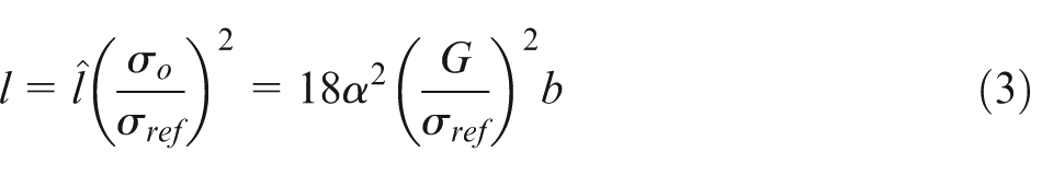
where α is a factor, G is the shear modulus and b is the Burgers vector.
The intrinsic material length scale
Applying the same method to the plot shown in Figure 5(b), the material length scales for the perfectly sharp cutting edge were 20 and 22 µm when determined from the cutting and thrust components, respectively. These values are highlighted as the round dots on the y-axis (cutting edge radius = 0) in the plots of Figure 6 which show variation of the material length scale with the cutting edge radius.
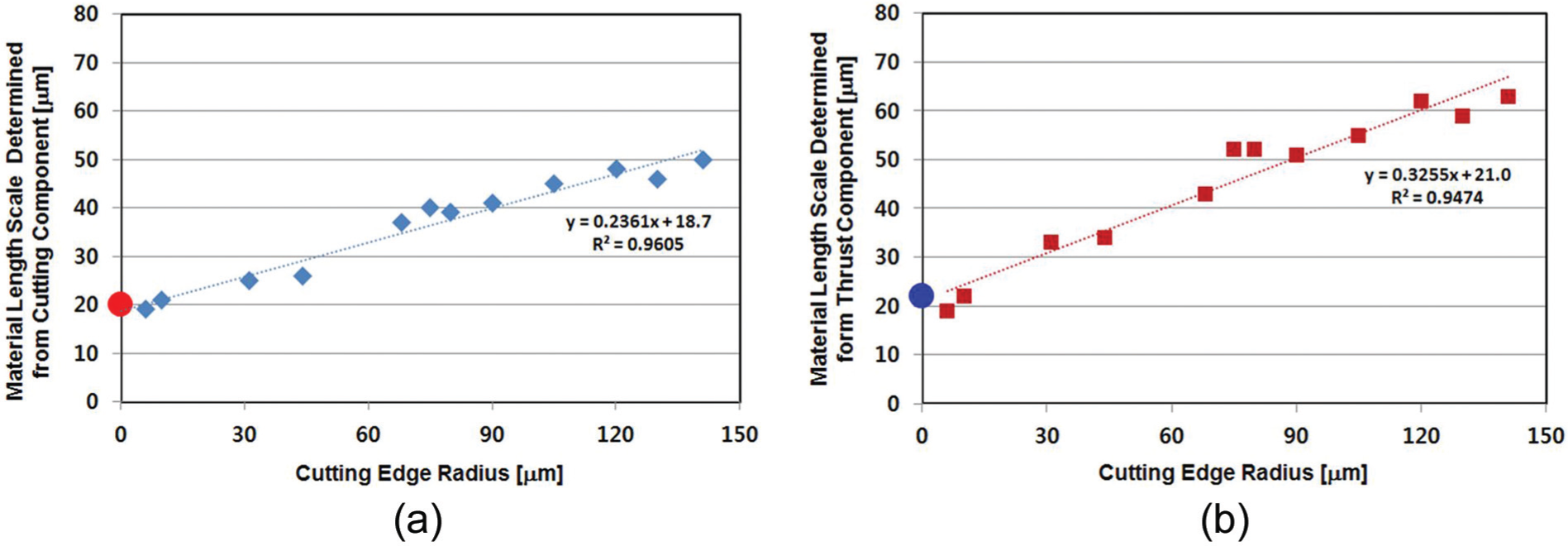
Material length scale with variation of cutting edge radius when determined from the specific coefficients in (a) cutting and (b) thrust directions.
In Figure 6, it is noted that the material length scale tends to monotonically decrease with the decrease of cutting edge radius, approaching the value obtained for the perfectly sharp cutting edge. This indicates that caution needs to be taken to null out the geometric size effect when determining the material length scale experimentally. For pure zinc, the geometric size effect on the material length scale seems to be negligible when the cutting edge radius is less than 10 µm. It is also noted that the slope of decrease is steeper for the thrust component than that for the cutting component in the figure. This again indicates that the effect of cutting edge radius is more salient in the thrust component than in the cutting component. Thus, it may be better to investigate the thrust component rather than the cutting component to see the effect of cutting edge radius more clearly.
Effect of cutting speed and material property onto the material length scale
Figure 7 shows the material length scale varied with cutting speed and cutting edge radius. The material length scale for the cutting speed of 940 mm/s was employed from the work of Liu and Melkote 19 while that for the cutting speed of 100 mm/s was obtained through the present study. In so doing, the material length scale shown in Figure 6 was recalculated from the resultant cutting force instead of the directional components—cutting and thrust. In this case, the material length scale with the cutting speed of 100 mm/s was found to be about 30 µm for the perfectly sharp cutting edge as indicated in Figure 7.
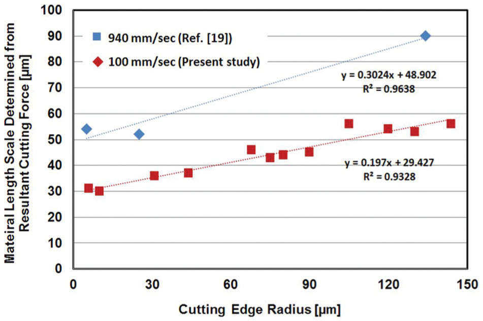
Material length scale with variation of cutting speed and cutting edge radius when determined from the resultant cutting force.
In Figure 7, it is clearly seen that the material length scale increases with the increase of cutting speed. With the lower cutting speed of 100 mm/s, the material length scales are found to be 31 and 56 µm for the cutting edge radii of 6 and 130 µm, respectively. With the higher cutting speed of 940 mm/s, contrastingly, the material length scales are found to be 54 and 90 µm for the cutting edge radii of 5 and 134 µm, respectively. Such increase may be related to the increase of strain rate in the primary/secondary deformation zone caused by the increase of cutting speed. Since zinc has high strain rate hardening sensitivity, 27 material strengthening should occur in the deformation zone with the increase of cutting speed which might cause the rise of the material length scale.
Integration of the intrinsic size effect into machining simulation
For machining simulation, it is necessary to construct the constitutive equation as given in equation (1), which shows that the flow stress (
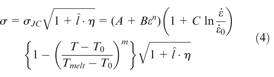
Here,
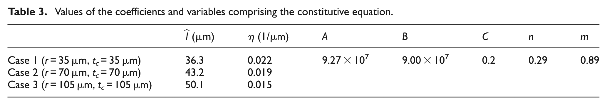
By comparing the specific cutting energy (the specific coefficient in cutting direction) acquired from cutting experiment and machining simulation, the effectiveness of the intrinsic size effect model as proposed above was validated. In so doing, additional cutting experiment was conducted using the 2D orthogonal machining setup as described in section “Pure 2D orthogonal machining configuration.” The same type of workpiece and cutting tool, and the same cutting speed as summarized in Table 1 were employed. However, the cutting edge radius was differed to 35, 70 and 105 µm while the ratio between the cutting edge radius (r) and the uncut chip thickness (tc) was fixed to 1.
The machining simulation was conducted using the commercial finite element method (FEM) software—AdvantEdge® provided by Third Wave Systems. The parameters for the Johnson–Cook model in equation (4) (A, B, C, m and n) were determined by the combined use of the tensile test and the optimization process which was performed with the objective of minimizing the errors between the experimental data and the simulation result as employed in previous studies.
28
The effective strain gradient (
Material properties of pure zinc.
Values of the coefficients and variables comprising the constitutive equation.
The results of the cutting experiment and simulation are shown in Figure 8. In the figure, the specific cutting energy is given for the cutting experiment and the simulation conducted with three different scenarios: (1) no intrinsic size effect considered (labeled as “w/o SG”), (2) the intrinsic size effect considered with the material length scale fixed at 29.4 µm which corresponds to that for the perfectly sharp cutting edge (labeled as “SG with ML fixed”) and (3) the intrinsic size effect considered with the material length scale varied (labeled as “SG with ML varied”). The simulation tends to slightly underestimate the specific cutting energy, but it is clearly seen that the specific cutting energy has maximum values for the third scenario while that for the first scenario has minimum values. Consequently, the errors as compared with the experimental results are largest for the first scenario while those for the third scenario are smallest. Therefore, to improve the accuracy of matching simulation, it is worthwhile to include the material length scale varying with the cutting edge radius in the intrinsic size effect model. This indicates that the efficient estimation of the material length scale and its integration into the intrinsic size effect model in machining would be necessary when simulating machining processes for design and optimization of cutting tools and conditions.
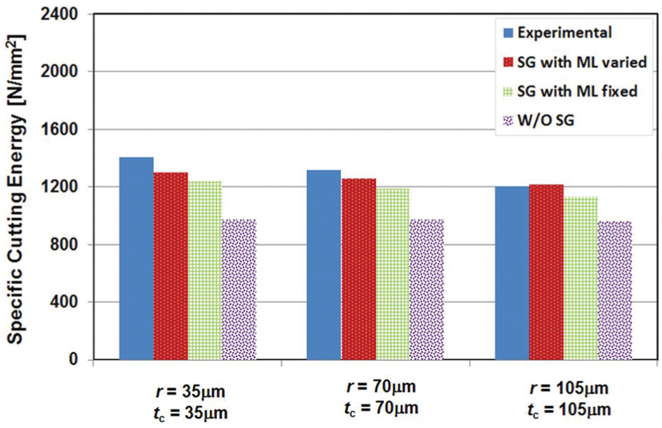
Comparison of cutting forces measured from the cutting experiment and predicted by the simulation with three different scenarios.
Conclusion
In this study, an efficient way of quantitatively investigating the intrinsic size effect in machining was developed through the following. First, the pure 2D orthogonal machining of pure zinc was conducted while the cutting edge radius and the uncut chip thickness were varied. Then, the relations between the cutting edge radius and the specific coefficients were investigated. The result showed that the specific coefficients monotonically increase with the increase of the cutting edge radius when the uncut chip thickness is fixed. The specific cutting coefficients for a perfectly sharp tool could be estimated by extrapolating the relations obtained for different values of the uncut chip thickness.
It was shown that the estimates of the specific coefficients for a perfectly sharp tool could be utilized for characterizing the material length scale to be embedded into the strain-gradient theory. It was found that the material length scale tends to increase with the increase of the cutting edge radius and the cutting speed, its sensitivity varying with material property, possibly the strain rate hardening sensitivity. The accuracy of machining simulation could be improved by employing the intrinsic size effect model which was determined through the method proposed in this study. This indicates that the proposed method is effective for investigating and modeling the intrinsic size effect in machining.
Footnotes
Declaration of Conflicting Interests
The author(s) declared no potential conflicts of interest with respect to the research, authorship and/or publication of this article.
Funding
The author(s) disclosed receipt of the following financial support for the research, authorship, and/or publication of this article: This research was supported by Basic Science Research Program through the National Research Foundation of Korea (NRF) funded by the Ministry of Education (NRF-2011-0025537).