
Abstract
In minimally invasive neurosurgery, there is a gap between the need for a micro-burr hole to be opened on the skull to expose the enclosed brain for further operation and the proper technology available. Conventionally, a burr hole is generated by a drilling perforator, which usually causes damage to the vital soft tissue beneath skull. Besides, because of the extremely low mechanical strength of a micro-drilling bit, a micro-hole cannot be generated on the hard skull by the conventional drilling method. To bridge this gap, an ultrasonic vibration-assisted micro-burr hole forming technique has been developed in this study and its effectiveness has been proved through in vitro experiment on cat skull. With the assistance of ultrasonic vibration (29.7 kHz), a micro-hole has been successfully formed on skull with a 300 µm diameter conically tipped tool. Ultrasonic vibration of a large amplitude is found beneficial because the thrust force can be greatly reduced by increasing the vibration amplitude. Moreover, the micro-hole forming is free of cutting and chips. The ultrasonic vibration is found to have a hammering effect similar to shot peening, and a layer of dense tissue is formed around the hole and no chip is generated in the hole forming process. Besides, since the ultrasonic vibration tool can only fragment hard bone tissue without causing damage to the soft tissue beneath skull, a safe micro-hole forming technique can be enjoyed. Based on the findings from this study, a micro-burr hole perforator can be developed for the next-generation minimally invasive neurosurgery.
Introduction
The burr hole is an entrance opened on the skull to enable the insertion of a thin surgery tool into brain for medical treatment or scientific research.1–3 Burr hole perforation is widely practiced in minimally invasive neurosurgeries. In the treatment of brain tumor, a thin trocar is inserted into brain through a burr hole to harvest the tumor tissue for further examination. 1 In cryogenic neurosurgery, a specially designed freezing cannula is delivered through a burr hole into brain to kill tumor tissue by freezing. 2 The conventional method for burr hole perforation is drilling, which has been used for decades in neurosurgery.1–5
Despite its wide application, there are a few serious problems with burr hole drilling. First, burr hole drilling is invasive and unsafe. The rotating drill bit will damage and remove any material it encounters. In the case of burr hole perforation, there is a layer of dura mater beneath skull which encloses and protects the brain.6,7 At bone–dura interface, over-run of the rotating drill bit would damage dura mater and even the brain.1–5 Second, it is quite difficult to drill a micro-hole on the hard skull bone. Drilling of the hard skull bone would generate a large drilling force/torque, and the micro-drill bit would just break instead of advancing into bone, imposing a serious safety issue in neurosurgery. Due to the lack of suitable techniques for micro-burr hole generation on skull, a large burr hole with a diameter of a few millimeters is generally drilled even for the insertion of a micro-surgery tool like the micro-electrode into brain.8,9 A new micro-burr hole opening technique is thus desired to make the surgery safer and less invasive.
Currently, various techniques have been developed for micro-hole fabrication on engineering materials.10–18 Sub-millimeter holes could be machined on metallic materials using electrochemical micro-drilling, 10 but this method cannot be used for micro-hole generation on skull because of bone’s electrical insulation property and also the safety issue. Generation of a 320-µm-diameter micro-hole on glass-fiber-reinforced plastic was realized by micro-drilling at a high spindle speed of 20,000 r/min or larger, 11 but the drill bit of ultra-high speed rotation may damage the soft tissue beneath skull. With the assistance of ultrasonic vibration, a micro-hole can be generated on hard materials by lapping. 12 Fine abrasive particles are required for material removal. 13 Falling of these particles into skull cavity may cause infection. Free abrasive particles are not required in ultrasonic-assisted drilling or grinding. 14 Micro-holes with a diameter of 10–20 µm have been fabricated by ultrasonic-assisted drilling/grinding.15,16 But, the rotating tool in ultrasonic vibration-assisted drilling or grinding still poses a threat to the soft tissue beneath skull. Although the above-mentioned methods are not suitable for micro-hole opening on skull, it has been empirically verified that ultrasonic vibration can help reduce the machining forces/torque.17,18 It may be workable to generate a micro-hole by penetrating a micro-tool into the skull bone with the assistance of ultrasonic vibration.
In this study, a novel ultrasonic vibration-assisted micro-hole forming technique has been developed to generate a micro-burr hole on skull without causing damage to the underlying soft tissue. This article is organized as follows. The ultrasonic vibration-assisted micro-hole forming technique is first introduced after a brief discussion on skull bone’s structural and mechanical properties. The effectiveness of this technique is then verified via in-vitro experiments on skull bone. Results and discussion are presented accordingly. In the end, a conclusion is reached.
Ultrasonic vibration-assisted micro-burr hole forming
Properties of skull bone
Human skull has a typical three-layer structure with a thickness of about 4–7 mm.19,20 The two outer layers are cortical/compact bone and the sandwiched layer is cancellous/spongy bone. Cortical bone and cancellous bone are similar in composition and mainly composed of collagen mineralized with carbonated apatite.21–23 The mineral takes up about 65% of skull’s overall weight, the organic (mainly collagen) takes up about 25% and the left is water. 23 Despite the similarity in composition, cortical and cancellous bone are quite different in structure. Cortical bone is composed of densely compacted mineralized collagen lamellae and has a low porosity of about 5%–10%.23,24 Cancellous bone has a cross-linked three-dimensional (3D) architecture with a high porosity of about 70%–95%. 24 Due to the difference in structure, cortical bone has a higher strength than cancellous bone. Young’s Modulus of the cortical bone varies from 5 to 45 GPa, while that of cancellous bone is up to about 3 GPa.25–27 Another thing worth mentioning is the viscoelastic periosteum, a thin fibrous membrane mainly composed of collagen, which can be taken as a layer of collagen coating on the skull bone.6,28 Existence of this polymer-like periosteum may influence the generation of exit burr as the skull bone is penetrated by the micro-tool.
Ultrasonic vibration-assisted micro-hole forming
A typical ultrasonic vibration system is composed of an ultrasonic driver/generator, a transducer, a horn and a tool. Electrical energy supplied from the driver is transferred into high-frequency mechanical vibration via the piezoelectric element of the transducer.13,29,30 Amplitude of the mechanical vibration is modified by a specially designed horn, through which the energy is transmitted to the ultrasonic vibration tool. High-intensity low-frequency (20–60 kHz) ultrasonic vibration is widely used in medical areas such as surgery and dentistry to fragment bone tissue.31–33 In this study, the employed ultrasonic vibration system (with the tool attached at its end) has a resonant frequency of 29.7 kHz. For the ultrasonic tool vibrating at frequency f and amplitude A, as it is fed into the skull bone at a feed rate of v0, its instant position and velocity are, respectively, expressed in equations (1) and (2)

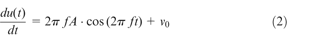
It can be seen from equation (2) that if v0 < 2πfA, the ultrasonic vibration tool would periodically separate from the skull bone; if v0 ≥ 2πfA, the tool is in continuous contact with bone. 34 In the hole forming process, intermittent tool–bone contact is desired. Otherwise, bone necrosis will be resulted from overheating generated due to the continuous contact between tool and bone.35,36 Thus, a feed rate smaller than 2πfA was used in this study.
In vitro experiment
Bone sample preparation
Skull bone harvested from the central part of the skull of 2-year-old dead cats was used in the experiment. Bone samples with a three-layer sandwiched structure were prepared to be 10 mm long and 4 mm wide. The thickness of the bone samples was about 1.5 mm. After sterilization using alcohol, bone samples were preserved in physiological saline solution (24 °C) to keep it hydrated. Before experiment, the bone sample was taken out of the saline solution, dried with paper tissues and secured onto a specially designed fixture. Experiment was carried out within 3 h after the death of the cat in an air-conditioned environment (about 24 °C).
Equipment
The 3D model of the ultrasonic device (supplied from Hangzhou Success Ultrasonic Equipment Co. Ltd., China) used in this study is shown in Figure 1(a). This device has a 300 µm diameter tungsten carbide ultrasonic tool with a taper shank (Figure 1(b)). According to the technical specifications provided by the manufacturer, this system has a resonant frequency of 29.7 kHz (with the micro-tool attached onto the system), and maximum amplitude measured at the tip of the micro-tool is 75 µm (peak–peak amplitude of 150 µm). The vibration amplitude can be changed by adjusting the output power of the ultrasonic driver. A larger amplitude can be acquired at a higher power level.
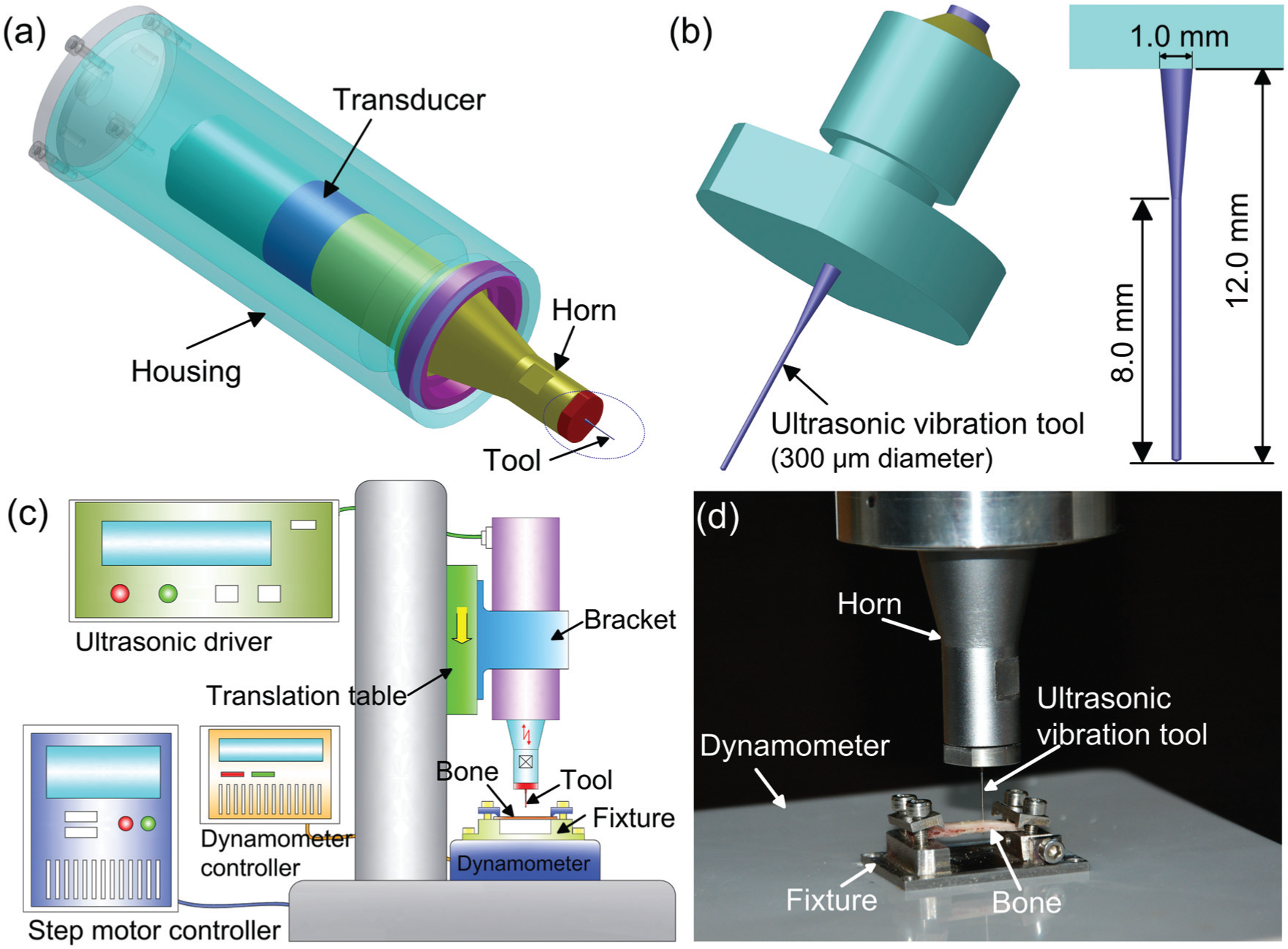
(a) Solid model of the ultrasonic vibration device, (b) the micro-ultrasonic vibration tool, (c) schematic diagram of the experimental setup and (d) tool–bone interaction during experiment.
A schematic diagram of the experimental setup is shown in Figure 1(c). The ultrasonic device was mounted onto a vertically placed translation table driven by a step motor. The bone sample was secured onto a fixture with its outer surface placed upward, and the fixture was fixed onto a dynamometer which was placed right below the ultrasonic vibration tool (Figure 1(d)). The dynamometer (1.0 mN resolution) was used to measure and record the thrust force in the hole forming process. Feed rate of the ultrasonic vibration tool toward the bone sample was 0.2 mm/s, smaller than 2πfA as calculated using equation (2).
Hole forming experiments
Experiment was carried out using a 300-µm-diameter 60° conically tipped tool (tip radius: about 50 µm) to verify the effectiveness of the proposed ultrasonic vibration-assisted micro-hole forming technique. Ultrasonic vibration’s effect on micro-hole forming was investigated by carrying out experiment under different vibration amplitudes. In the study, hole forming experiment was carried out at three different power levels 99%, 60% and 40%, which, respectively, corresponded to ultrasonic vibration of high, medium and low amplitude. The method for controlling vibration amplitude is similar to that used in the reference study. 13 Under each amplitude, 12 holes were generated. The thrust force exerted on the bone sample in the hole forming process was recorded by the strain gauge dynamometer for later analysis. Microstructure of the bone tissue around the formed micro-hole was observed using scanning electron microscopy (SEM) to investigate the mechanism of ultrasonic vibration-assisted micro-hole forming on skull.
Results and discussion
Ultrasonic vibration-assisted penetration
It is found in the experiments that if the micro-tool is fed into bone without ultrasonic vibration, the tool would break instead of advancing into the bone. However, with the assistance of ultrasonic vibration, a micro-hole can be successfully formed on the hard skull bone by the 300 µm diameter ultrasonic vibration tool. In order to uncover the mechanism of this phenomenon, micro-hole forming experiment was carried out under three different amplitudes. The maximum thrust forces in the hole forming process under different amplitudes were calculated. The averaged maximum thrust force for micro-hole forming under each amplitude is shown in Figure 2.
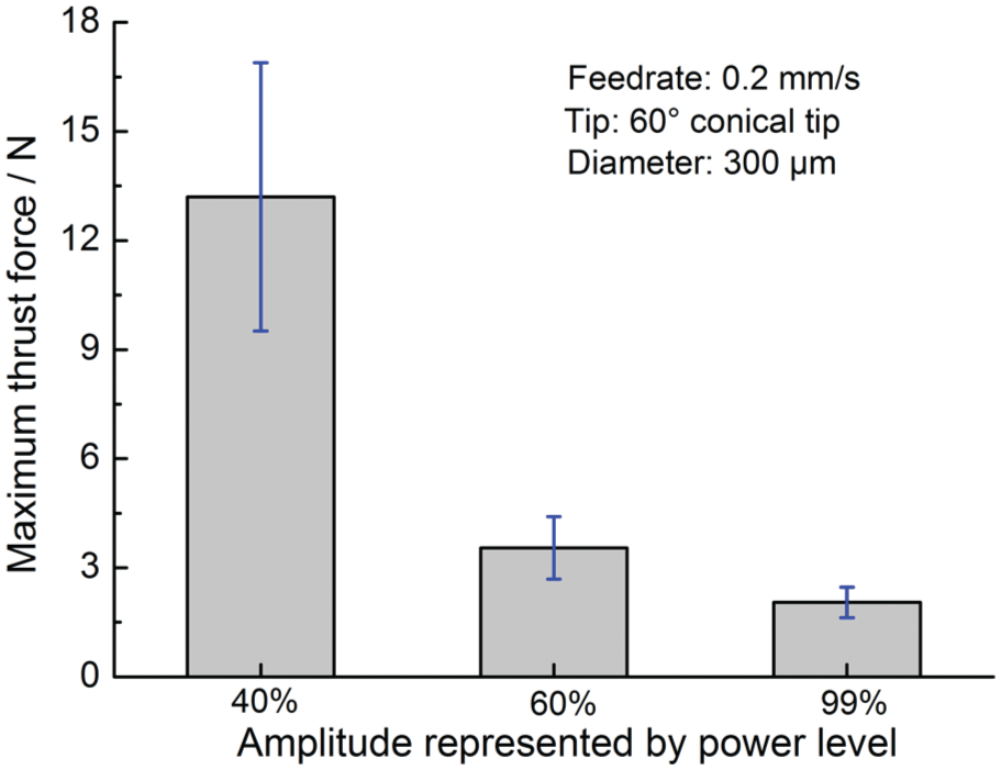
The effect of vibration amplitude on the maximum thrust force.
It is shown in Figure 2 that the maximum thrust force decreases with the increase in the vibration amplitude. This trend is consistent with that observed in ultrasonic vibration-assisted drilling of cortical bone. 37 Divide the maximum thrust force by the cross-sectional area of the 300 µm diameter tool. The apparent ultimate stress σap experienced by the bone tissue in the hole forming process can be acquired. The calculated average apparent ultimate stress σap at the 40%, 60% and 99% power level is, respectively, about 186.8, 49.5 and 28.0 MPa. Fitting these data by a linear equation using the method of least square, the relationship between vibration amplitude and bone’s apparent ultimate strength is shown in equation (3)

where σap (unit: MPa) is the apparent ultimate strength of the skull bone; σ0 (247.2 MPa) is the calculated nominal ultimate strength of cortical bone, which is of the same order of magnitude with that reported in other studies.25–27χ denotes the vibration amplitude, which is represented by the ultrasonic power level in percentage (from 0% to 100%), and a larger χ means a higher vibration amplitude.
Finite element analysis of the tool–bone interaction
In order to investigate the mechanism of ultrasonic vibration-assisted micro-hole forming, finite element analysis was carried out. Many finite element models have been developed to study the material removal processes such as turning or drilling.38,39 But, few studies were available on ultrasonic vibration-assisted hole penetration in bone. In this study, finite element analysis of tool–bone interaction was carried out with Abaqus/Explicit. Cortical bone’s Young’s modulus and Poisson ratio used in the simulation were, respectively, 15 GPa and 0.3.40,41 Density of cortical bone was 1650 kg/m. 42 Bone’s plastic behavior was represented using the Johnson–Cook (JC) model, which has been widely used in the simulation of bone cutting or drilling. The parameters for JC model were adopted from the reference study. 21 As for bone tissue’s failure strain/stress, it is affected by the strain rate.21,41 For the micro-tool vibrating with the amplitude of 75 µm and the frequency of 29.7 kHz, its peak speed can be up to 14 m/s, while its lowest speed is just 2.0 × 10⁻⁴ m/s. Thus, bone’s strain rate would experience dramatic fluctuations. To incorporate this effect, published data on cortical bone’s failure strain under different strain rates were adopted in the simulation. 21
The 3D model of the tool–bone interaction established in Abaqus/Explicit is shown in Figure 3. The 300-µm-diameter tool was modeled as a rigid body and constrained in all directions except the translation along the z-axis. Ultrasonic tool’s motion along the z-axis was defined by equation (1), in which f was 29.7 kHz and v0 was 0.2 mm/s. The 2.0-mm-diameter bone sample had a thickness of 0.5 mm. Perimeter of bone sample’s bottom surface was constrained in the x-, y-, and z-directions. The sidewall was not constrained, enabling the tissue move aside upon the penetration of the micro-tool, which is consistent with the real situation. In the central part, the bone sample was portioned into a part of 0.4 mm diameter. This central part was finely meshed and had 400,000 C3D8R elements. Outer part of the bone was meshed with 110,512 C3D4 elements for better computation efficiency. In the simulation, distortion control was adopted to prevent pre-mature termination of the computation which may be caused by extremely large element distortion. Tool–bone interaction was defined as general contact/explicit. Friction was not considered due to transient tool–bone contact under ultrasonic vibration. Simulation was then carried out to gain detailed understanding of bone’s deformation behavior.
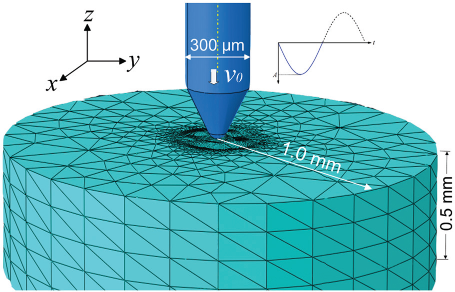
Three-dimensional finite element model of tool–bone interaction in Abaqus.
Development of the stress in bone tissue ahead of the conical tip in two successive cycles of ultrasonic vibration (75 µm amplitude) is shown in Figure 4. The penetration forces experienced by the micro-tool under different vibration amplitudes are compared in Figure 5. In a single cycle of tool–bone interaction, penetration depth of the micro-tool into bone depends on the vibration amplitude. At a higher amplitude, the indentation depth is larger and more tissue would be deformed. In order to compare the thrust force under different amplitudes, the volume of tissue deformed should be considered, and the thrust force is thus presented as force per volume of material deformed (Figure 5(a)).
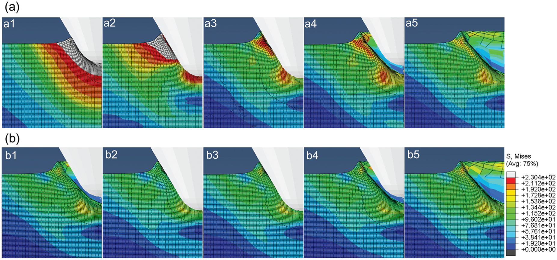
Distribution of equivalent stress (MPa) in bone at different depth of indentation under the amplitude of 75 µm (a) in the first cycle of tool–bone interaction and (b) in the second cycle of tool–bone interaction.
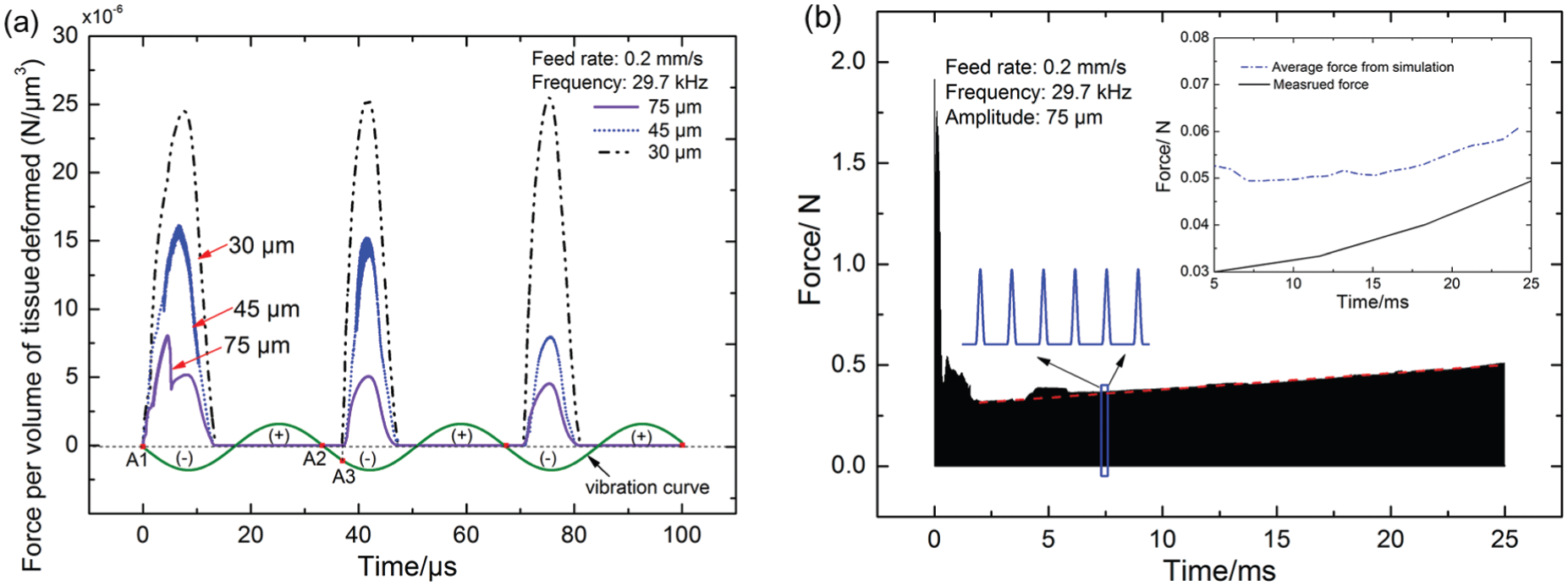
Penetration force acquired from simulation: (a) penetration forces exerted on the micro-tool under different vibration amplitudes and (b) evolution of the penetration force with the advancement of the micro-tool into bone.
It is shown in Figure 4(a) that as indentation depth increases, tissue deformation accumulates, bone tissue ahead of the tip would experience plastic deformation and a small pile-up develops around the conical tip (Figure 4(a1–a3)). At the same time, an increased penetration force is exerted on the micro-tool as shown in Figure 5(a). When the micro-tool retracts, the deformed tissue would experience elastic recovery, and the stress in bone tissue decreases (Figure 4(a4 and a5)), and a reduction in the penetration force is also observed (Figure 5(a)).
After tool retraction, residual stress exists in the sub-surface layer due to the plastic deformation as shown in Figure 4(a5). The residual plastic deformation also has a great influence on subsequent tool–bone interaction. In the second cycle of ultrasonic vibration, tool–bone contact occurs a little later than that in the first cycle, the stress in bone tissue at the same indentation depth is smaller than that in the first cycle of vibration as revealed by comparing Figure 4(a3) and (b3), and the penetration force is also smaller in the second round of the tool–bone interaction as shown in Figure 5(a). This may be caused by the tissue damage in the first cycle of vibration; thus, a smaller stress and penetration force are experienced in subsequent cycles of tool–bone interaction. However, under the amplitude of 30 µm, decrease in the penetration force is not evident (Figure 5(a)). This is likely because at a small indentation depth of 30 µm, no evident tissue damage is resulted from the first cycle of tool indentation. Thus, the thrust force in the second or third round of tool–bone interaction does not reduce evidently. In reality, micro-cracks would initiate and develop in bone tissue under ultrasonic vibration. This would promote tissue failure and reduce the penetration force in the second or third round of tool–bone interaction under a small amplitude of 30 µm. But, due to the lack of available constitution models, bone tissue’s brittle behavior was not incorporated in the simulation. This would be an important sphere for future study.
Besides, tool–bone interaction under the amplitude of 45 and 30 µm was also investigated. Penetration forces are compared in Figure 5. It can be seen that the thrust force decreases with the increase in vibration amplitude. This is consistent with the experimental findings shown in Figure 2. Amplitude’s effect on penetration force is thought to be related with cortical bone’s strain rate–dependent mechanical properties. As experimentally verified, cortical bone fails at a smaller strain under a higher strain rate. 21 A higher strain rate would be experienced by bone tissue at a larger amplitude, leading to fracture of bone tissue at a smaller strain/deformation. Thus, a smaller penetration force would be resulted. Besides, under a larger amplitude, intensity of tool–bone interaction is stronger, and more micro-cracks would be initiated. Crack propagation also promotes the failure of bone tissue and helps reduce the penetration force under a larger vibration amplitude.
Another important phenomenon observed is that the penetration force becomes larger with the increase in time or penetration depth as shown in Figure 5(b). This is because as the micro-tool is advanced into bone, more tissue is deformed in a single cycle of vibration, leading to a larger penetration force exerted on the micro-tool. The average force acquired from simulation is further compared with the measured force in the inset of Figure 5(b). A similar increasing trend is observed in both curves. But, the simulated force is larger than the measured force. This may be related with bone’s brittle behavior. Crack propagation in bone under ultrasonic impact could promote tissue failure. This contributes to the smaller penetration force observed in the experiment. Besides, as revealed in Figure 4, because of the high-intensity tool–bone impact, bone tissue ahead of the tool would undergo plastic deformation and be squeezed aside. In this process, microstructure of bone tissue around the hole would be altered. In order to investigate this effect, bone samples were observed under SEM.
Microstructure of bone tissue around the formed hole
The formed micro-holes were firstly cleaved perpendicular to its axis and observed with SEM. Acquired SEM images are shown in Figure 6. A layer of dense tissue can be observed around the hole and a dramatic change in the microstructure of bone tissue along the radial direction can be clearly detected in Figure 6(b). For the bone tissue far from the formed hole, layers of mineralized collagen lamellae can be observed and many voids can also be detected as seen in Figure 6(c). This structure is similar to that reported in other literatures. 23 However, for the bone tissue around the hole, it is densely compacted and layered structure of mineralized collagen lamellae and porosity could not be detected (Figure 6(b) and (d)).
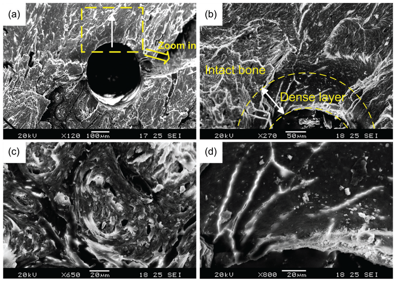
SEM images of the microstructure around the formed hole: (a) cross section of the micro-hole, (b) the dense layer around the hole, (c) microstructure of the intact bone and (d) microstructure of the dense layer.
The formed micro-hole was also cleaved longitudinally to observe its inner surface. Typical SEM images on the micro-texture of the formed hole are shown in Figure 7. The formed micro-hole is found to have a smooth inner wall (Figure 7(a)), and many micro-grooves can be observed on the inner surface along the feed direction (Figure 7(b)), which is thought to be caused by the friction between the tool and the inner wall. At a smaller scale, the inner wall is revealed to have a micro-texture different from that of the intact bone. 43 The intact bone is composed of layers of mineralized collagen lamellae (Figure 7(c)). However, there are numerous pits on the surface of the inner wall (Figure 7(d)), which is similar to the texture of the surface prepared by shot peening. 44 This phenomenon is thought to be related with the high-frequency “hammering” of the ultrasonic vibration tool on the bone tissue.
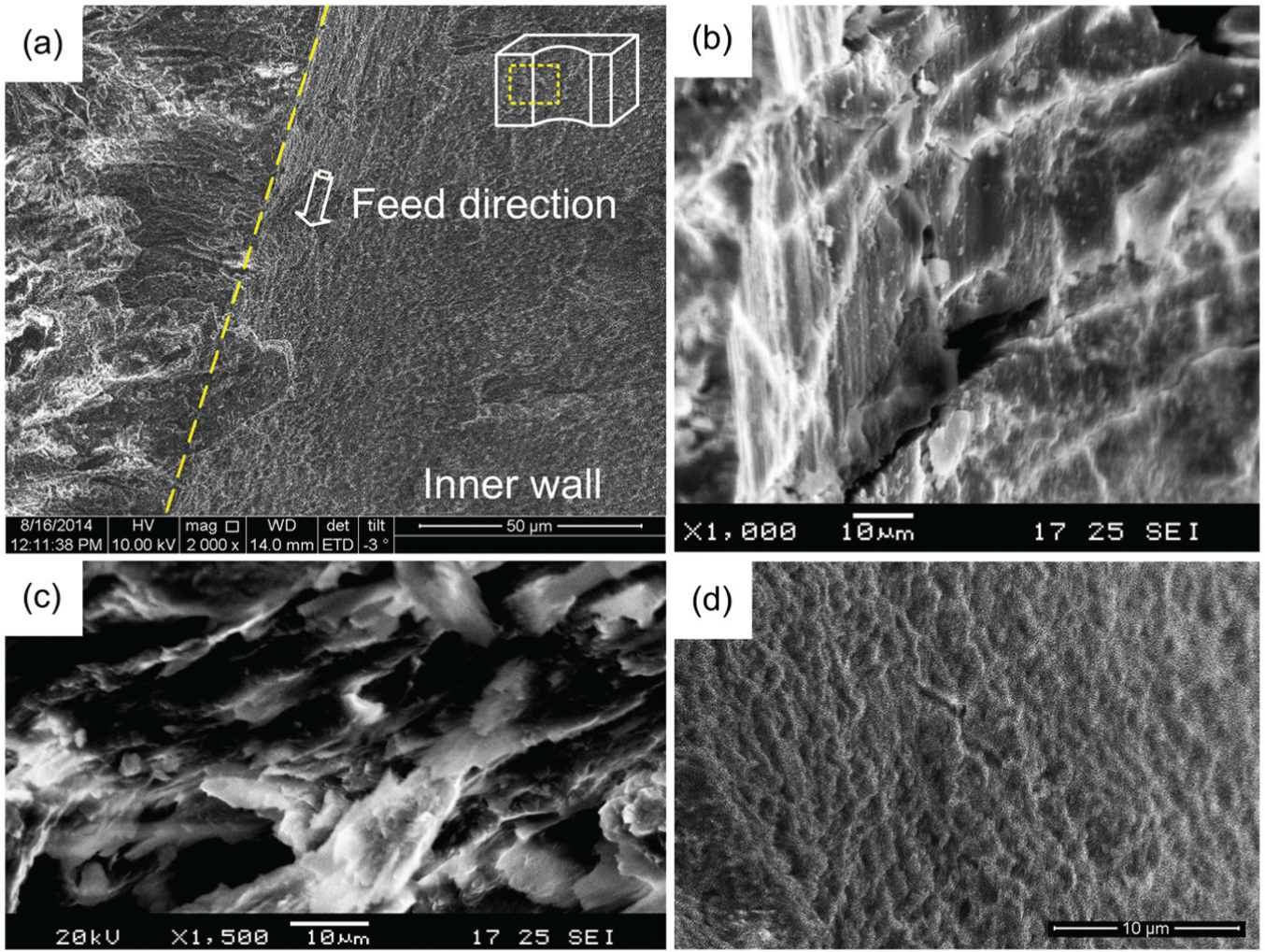
SEM images of micro-hole’s inner surface: (a) the overall view, (b) micro-grooves on the inner wall, (c) microstructure of intact bone and (d) micro-texture of the inner surface.
Exit burr generation
An exit burr was generated at the penetration of the bone by the ultrasonic vibration tool. When a conically tipped tool is used, a pyramid burr with multiple facets (usually between 3 and 5) would be generated. SEM images of a typical exit burr are shown in Figure 8. On the inner surface of the exit burr, a layer of dense tissue is found, and no lamellae or void can be detected in the attached dense material as shown in Figure 8(b). This dense layer is thought to be resulted from the collaborative effects of bone tissue’s elastic, plastic and brittle properties. Under high-frequency hammering of the ultrasonic vibration tool, bone tissue ahead of the tool would be plastically deformed and pushed forward. The plastically deformed tissue would be forced to attach onto the inner side of the exit burr when the bone is penetrated.
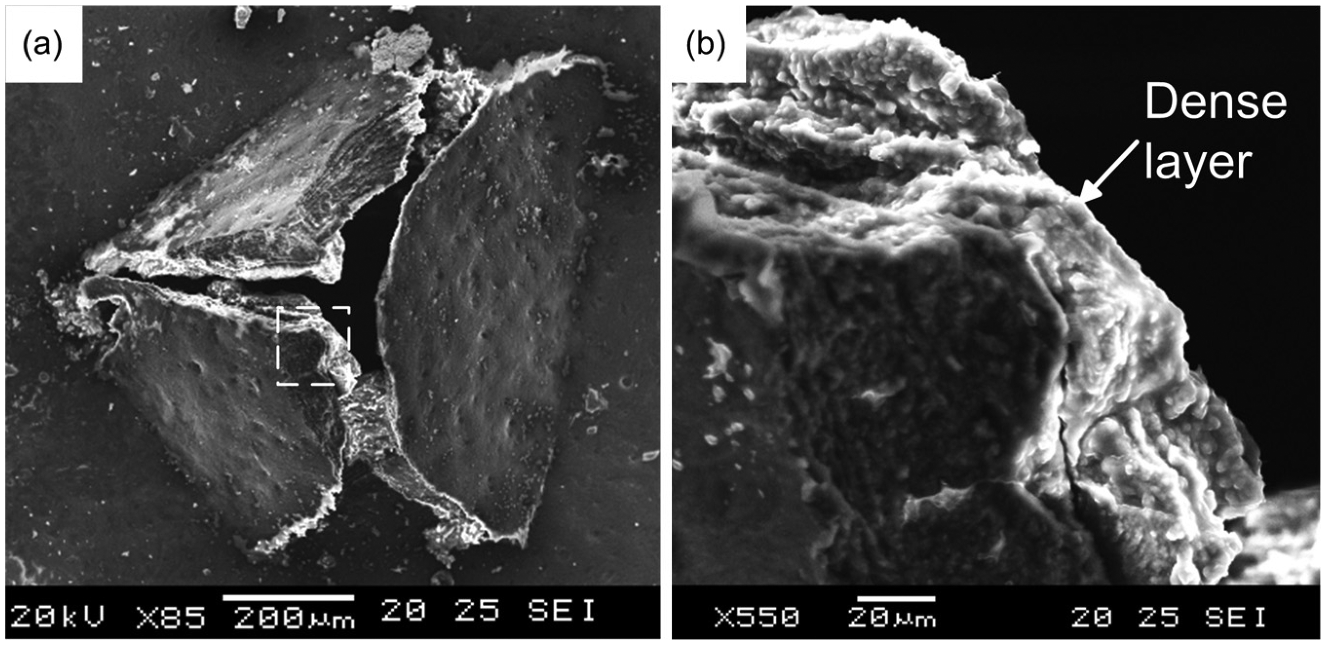
SEM images of the exit burr: (a) the exit burr and (b) the dense layer on exit burr’s inner surface.
As for the generation of the exit bur, it is thought to be related with crack propagation in the mineralized collagen lamellae (Figure 9). As the tool is advancing through the bone, the last few layers of bone lamella cannot withstand the thrust force and will bulge out (Figure 9(a) and (b)). Along with the bulging, cracks will initiate and propagate along the radial direction due to the tension stress in the bulged bone lamellae as illustrated in Figure 9(b) and (c). At the same time, crack also initiates around the corner of the tool (point A in Figure 9(a)). This kind of crack would propagate in an oblique plane toward the surface of the skull bone upon further advancement of the tool. The crack propagation plane can be observed after selective removal of one face of the pyramid burr, as shown in Figure 9(e) and (f). Besides, another important feature of the exit burr noticed in Figure 9(d)) is that unlike drilling or grinding, no chip is generated in the ultrasonic vibration-assisted micro-hole forming process. The generated burr is still attached onto the bone and does not fall off. This is mainly due to the existence of periosteum on the inner surface of skull bone. This layer of soft tissue would deter crack propagation and “glue” the exit burr onto bone’s surface. The chip-free burr hole forming process would be beneficial since it can reduce the chance of infection, which could be caused by the falling of bone debris deep into the burr hole.
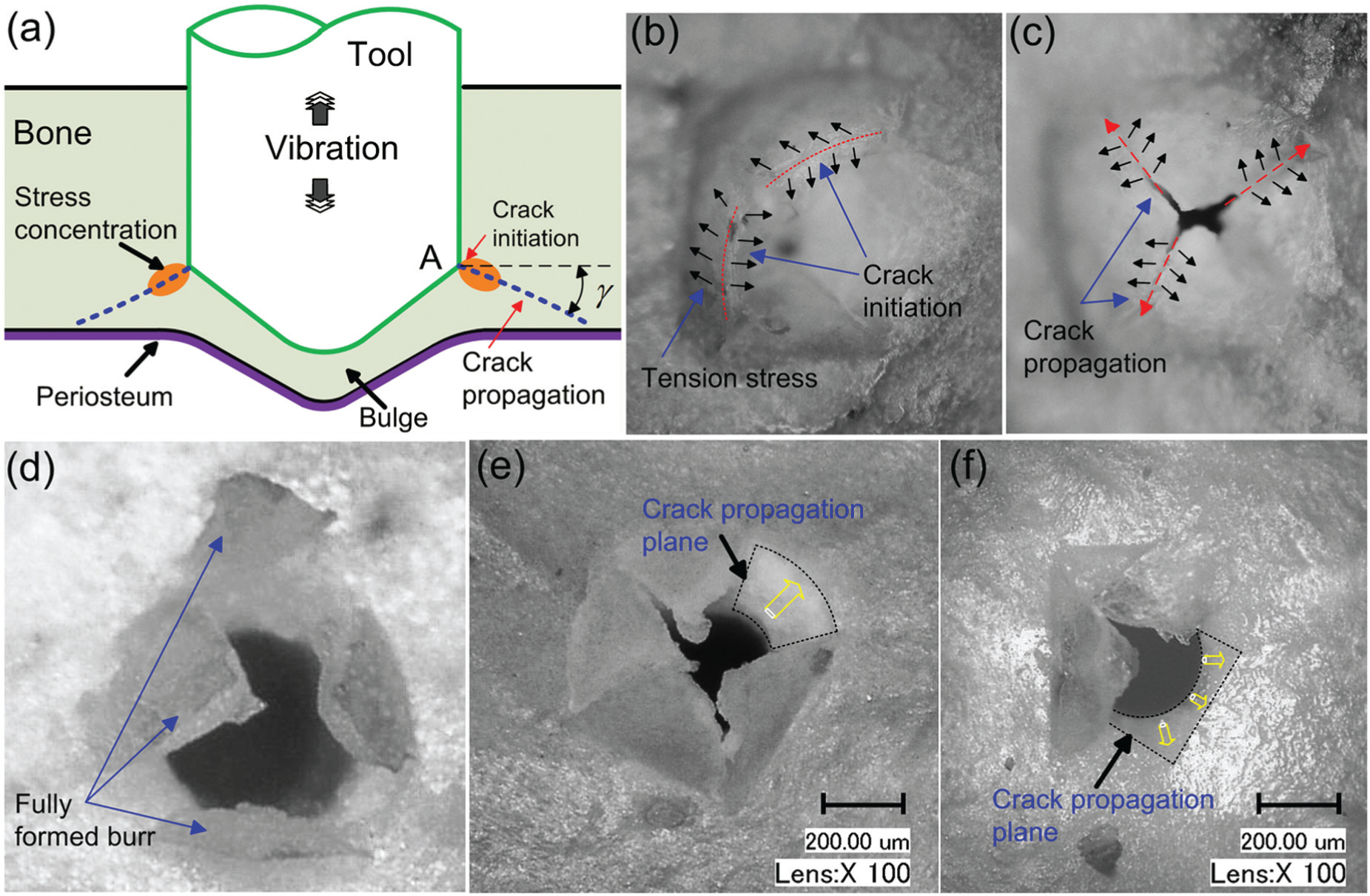
(a) Schematic diagram of the exit burr generation, (b) the bulged bone lamellae before burr generation, (c) crack propagation in the bulged bone lamellae, (d) the fully formed exit burr, and (e) and (f) the exposed crack propagation plane after selective removal of the exit burr.
Detection of the hole forming termination
A typical evolution of the thrust force in the hole forming process is shown in Figure 10. A few important features can be detected in this plot. Tool–bone contact occurs at point A and an abrupt increase in the thrust force is observed. At point B, the thrust force reaches a peak value and starts to reduce. This means that the outer layer of cortical bone has been penetrated and the tool starts to penetrate into the sandwiched spongy bone. Due to spongy bone’s high porosity and low mechanical strength, the thrust force decreases after point B. The tool gets into contact with the inner layer of cortical bone at point C, and the thrust force increases again. Penetration of the bone begins at point D and finishes at point E. After point E, a small force still exists. This is thought to be caused by the friction between the generated exit burr and the ultrasonic vibration tool. Thus, point E can be taken as the termination signal of the hole forming process.
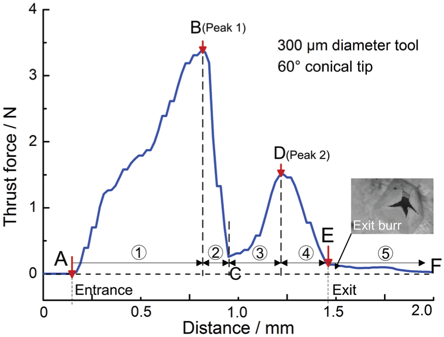
Typical evolution of the thrust force in the hole forming process observed in the experiment.
Based on the information discussed above, it is possible to control the hole forming process by monitoring the thrust force. Upon detection of the hole forming termination point E in the force curve, the skull bone would have been penetrated, and the ultrasonic tool can be retracted. Thus, no damage would be caused to the soft tissue like dura mater beneath the skull bone, and the cerebrospinal fluid (CSF) around the brain will not leak out. Thus, a micro-hole can be safely formed on the hard skull by detecting the termination point on the thrust force curve in the hole forming process. Besides, it has been verified in other studies that the accident contact between the ultrasonic vibration tool and the soft tissue would not cause damage to soft tissue.31,32 This finding would help eliminate the concern on the safety issue of the ultrasonic vibration-assisted micro-hole forming technique.
Conclusion
In this study, a pioneering micro-hole forming technique has been developed. With the assistance of ultrasonic vibration, a micro-hole can be formed on the hard skull bone.
The thrust force exerted on the micro-tool can be greatly reduced with the increase in vibration amplitude; thus, ultrasonic vibration of a high amplitude is preferable. Besides, the hole forming termination can be automatically detected by monitoring the thrust force. The ultrasonic vibration tool can be stopped at bone–dura interface, no damage will be caused to the soft dura mater beneath skull and no CSF leakage will be resulted. Moreover, no chip is generated in ultrasonic vibration-assisted hole forming process. This chip-free and CSF leakage-free burr hole generation has never been realized before. Compared with the conventional drilling method, the technique developed in this study has the following merits.
A micro-burr hole can be formed on the hard skull, enabling the insertion of a micro-surgery tool into brain in a truly minimally invasive manner.
The developed micro-hole forming technique is safer. Unlike the rotating drill bit which damages any tissue it encounters, the ultrasonic vibration tool used in this study can safely form a micro-hole on the skull bone without causing damage to the underlying soft tissues like the dura mater.
No chip is generated in the hole forming process, and this would reduce the chance of infection caused by falling of bone chips into the burr hole.
In ultrasonic vibration-assisted micro-hole forming, tool–bone interaction directly affected the tip geometry of the micro-tool. Tip geometry’s effect on the hole forming process should be investigated in the future. Besides, high-intensity tool–bone interaction may cause temperature rise in the bone tissue around the formed hole, which may lead to bone necrosis. Study on the heat effect during hole forming is also desired in order to clarify the safety issue of the micro-hole forming technique developed in this study.
Footnotes
Acknowledgements
The authors would like to present sincere acknowledgment to Mr Hou Haowen, Mr Zhu Binbin and Mr Lv Shunpeng for their kind help on sample measurement.
Declaration of conflicting interests
The author(s) declared no potential conflicts of interest with respect to the research, authorship and/or publication of this article.
Funding
The author(s) received no financial support for the research, authorship and/or publication of this article.