
Abstract
Determining the movement errors due to mechanical parts in computer numerical control devices is an important part of studying manufacturing and production. The propelling mechanical system of a computer numerical control device consists of engine, coupling, bearing, knot and leading rail. Each of these parts has an error value which causes manufacturing error in producing industrial parts. Although using closed-loop system has helped to solve this problem, still there are systems that use open loop. In this study, using Mooney–Rivlin model for flexible couplings, we calculated the errors due to the deformation of elastomeric medium, which is made of thermoplastic polyurethane. Using the ANSYS software, we simulated the three-dimensional model of medium to obtain elastic deformation. The loading type was chosen in terms of torque and stepper revolution of engine. At fixed 500 r/min, the effect of torque and engine stepper on the deformation was investigated, and the results obtained were compared with the simulations from experimental work on a computer numerical control desk with stepper 1.8 and 2.4 N m and ABBA coupling of model SRG-40C and ball screw of milled diameter 25 pitch 5 class C which showed a good confirmation.
Keywords
Introduction
Coordination in rotational systems is an important issue. The greatest statistics of damage in rotational mechanical equipment can be attributed to this issue.1,2 To install the equipment, accurate measurement watches with great precision at 0.02 mm/m are used. Required control of revolution is performed with interferometry. After the driving system is run and the suitable rotation with revolution and torque is obtained, there is a little delay and noise in the system. 2
In most cases, using flexible couplings made of polymer materials has solved the problem. 1 With this equipment, the axial errors up to 1 mm and angular errors up to 1° can be removed. The intermediary materials used as flexible elements in these couplings are made of specific materials. The most recent type widely used in very accurate systems, such as computer numerical control (CNC) and coordinate measuring machine (CMM) devices, is thermoplastic polyurethane (TPU). 3 These materials have properties between elastic and thermoplastic materials. Very good flexibility, resistance against erosion, oil and acid environment, and high mechanical strength are among their properties. 4
Figure 1 shows the internal structure of TPU, consisting of two soft chain parts connected with a hard chain. Using these materials in motion conveying systems has brought about a basic problem due to their polymer nature. These materials show different behaviors in different temperatures and loadings. The mechanical properties and characteristics of a flexible coupling are introduced and the mechanical behavior of its intermediary medium is modeled. After loading, according to real conditions, by ANSYS and introducing binomial constants of Mooney–Rivlin, the elastic deformations are calculated.
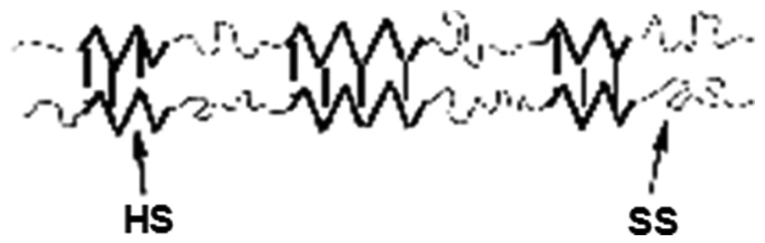
A schema of the structure of thermoplastic polyurethane materials.
Studying and modeling the nonlinear elasticity behavior of TPU
The reason that elastic materials show a very different behavior from metals is their microscopic characteristics. Metals are consisted of crystal grids which have remarkable order. In contrast, the molecules of rubbers are consisted of carbon atoms dependent on a long chain the same as a piece of strings. As the C–C binding rotates, there is a possibility for these interwoven long chains of polymer to rearrange themselves into numerous shapes. As long as an irregular chain acts as a spring, constant jump demands lateral connection to stop viscous flow. In rubber, chemical bound is established between rubber and sulfur, whereas physical dependencies have an effect like the performance in an elastomer thermoplastic materials. According to Figure 1, TPU is consisted of soft and hard segments to give some properties between rubber and thermoplastic.
In this case, lateral connection is used to control the toughness of rubber. Figure 2 compares the elasticity modulus of thermoplastic materials (TPU) with other common engineering materials. The rubber to polycarbonate range for TPU elasticity modulus is remarkable.
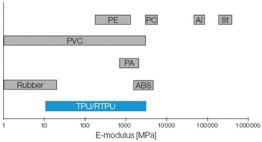
Comparison of TPU elasticity modulus with other engineering materials. 4
From the mechanics of continuum media, the elasticity modulus of rubber can be deduced from the molecular surface which expresses the material behavior macroscopically. 5 In this article, TPU elasticity is developed in terms of the first principle. Then, a traditional method in a continuum media is proposed regarding a form of strain energy density and use of the limitations governing the basic response by the second law of thermodynamics so that we get the tension–stress response. To model the response of TPU materials, the strain energy which is a function of deformation gradient in the form of left tensor of Bij = Fi,A Fj,A is used. This method is referred as Mooney–Rivlin based on which the initial isotropic material must obey specific symmetries regarding the strain energy function.
Rivlin (1948) supposed logically that strain energy must be expressed as a polynomial of I1 and I2 (equation (1))
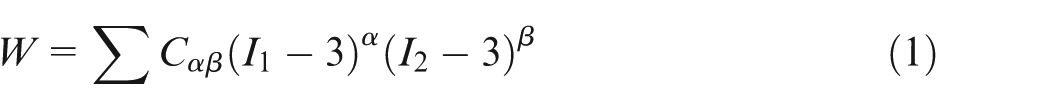
where I is the Mooney–Rivlin coefficient. Strain energy is written in terms of I1 − 3 and I2 − 3 versus I1 and I2, respectively, to guarantee the conformity between zero strain and zero strain energy.
Based on the type of material and deformation, that is, the input of experimental test, the number of the terms in the equation is chosen. For example, choosing
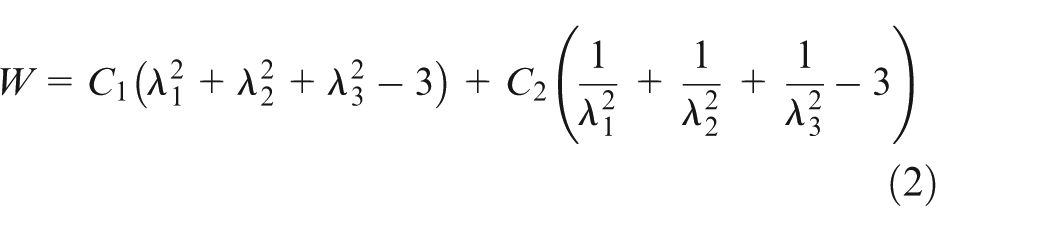
A simple model to determine the behavior of TPU materials with good approximation is the binomial expansion of Mooney–Rivlin used in this test. In this case, strain energy function is considered for the first and second constants of left deformation tensor. Supposing the material is isotropic and incompressible, the strain energy equation is written as the following (equation (2))
For uniaxial test, the tensions are
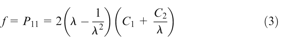
As the area in deformed shape can be obtained by scale and dimension measurement in directions x1 and x2 by
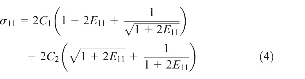
The expansion of the last three terms of equation (4) in series along with the assumption of negligible E11 results in equation (5)

Therefore, for small strain, the elasticity modulus is written as
Determining Mooney–Rivlin constants to simulation and solution
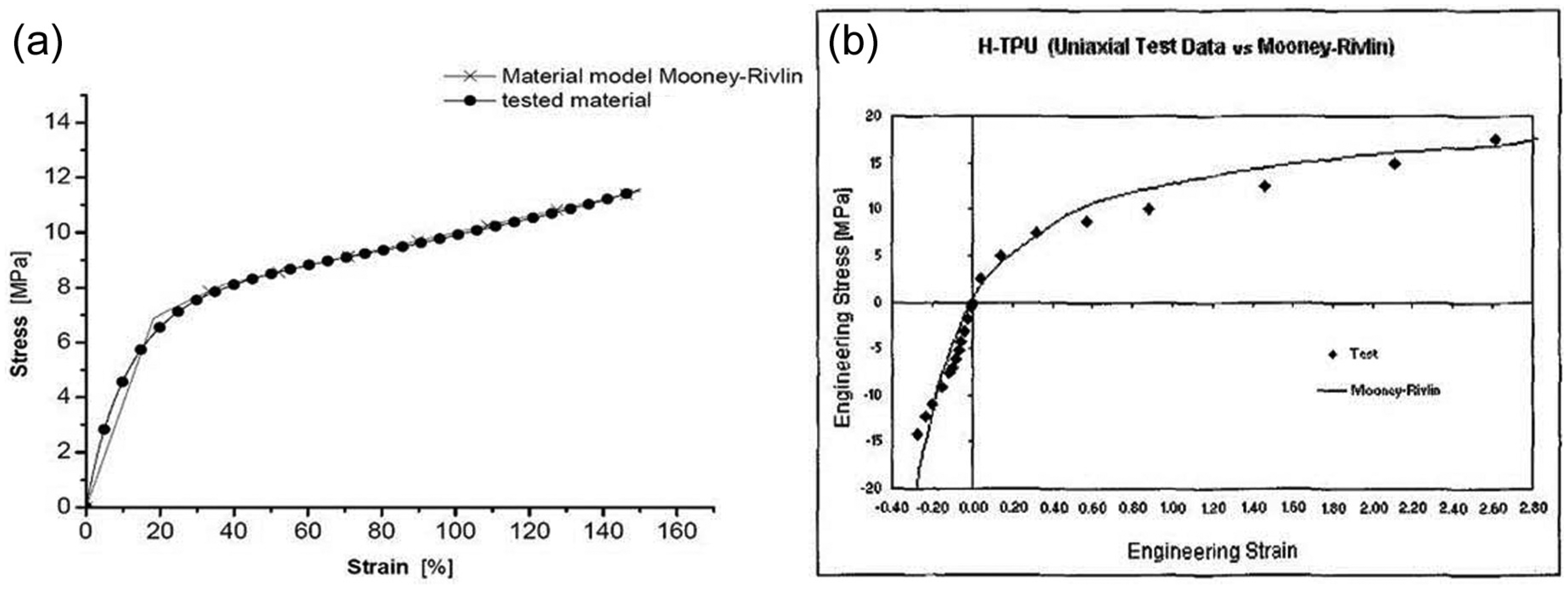
To predict the tension–strain curve, we should have used the tension test of CNC sample which became impossible due to financial limitations. Instead, the results of previous literature4,6,7 were used to obtain Mooney–Rivlin curve. In both cases, the curve results are almost similar. This case is shown in Chart 1. The constant coefficients of C1 and C2 obtained from the curves are (equation (6))

Real model of flexible coupling
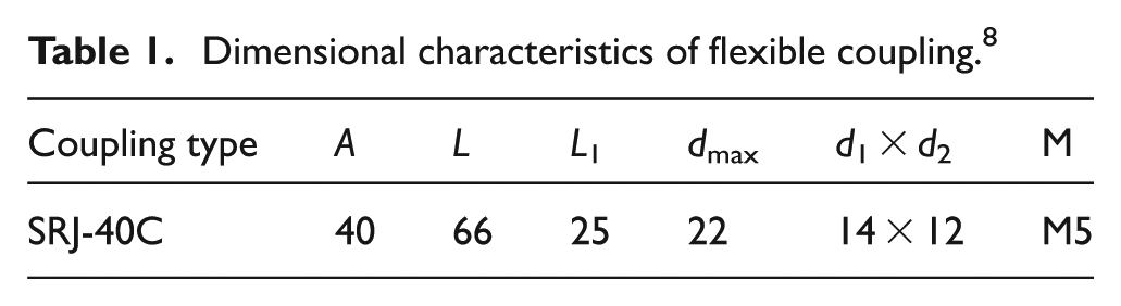
Dimensional characteristics of the coupling used are summarized in Table 1. The metal part of coupling is aluminum alloy.
Dimensional characteristics of flexible coupling. 8
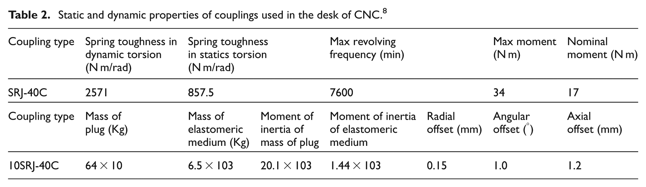
Permanent coupling is subjected to stopping conditions and frequent sudden rotations of desk driving system. Therefore, it is necessary to determine the static and dynamic properties of the couplings, as stated in Table 2.
Static and dynamic properties of couplings used in the desk of CNC. 8
The three-dimensional model is prepared with solid work software and shown with real model in Figure 3.
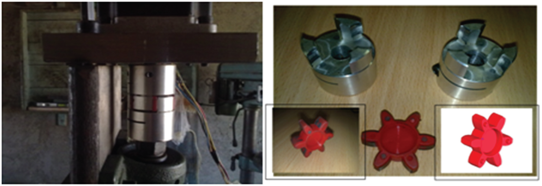
Flexible coupling of aluminum and elastomeric medium of TPU.
To consider the property of torque loss in high rotational speeds, the torque applied by stepper motor was extracted at 48 V from torque–speed curve (2) by stepper motor manufacturer. To prevent the extra loss of torque, the maximum speed was chosen to be 600 r/min. From Graph 1, the percentage of torque loss is 25%.
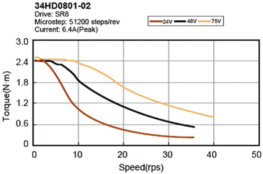
Torque–speed curve of stepper motor from the manufacturer catalog. 9
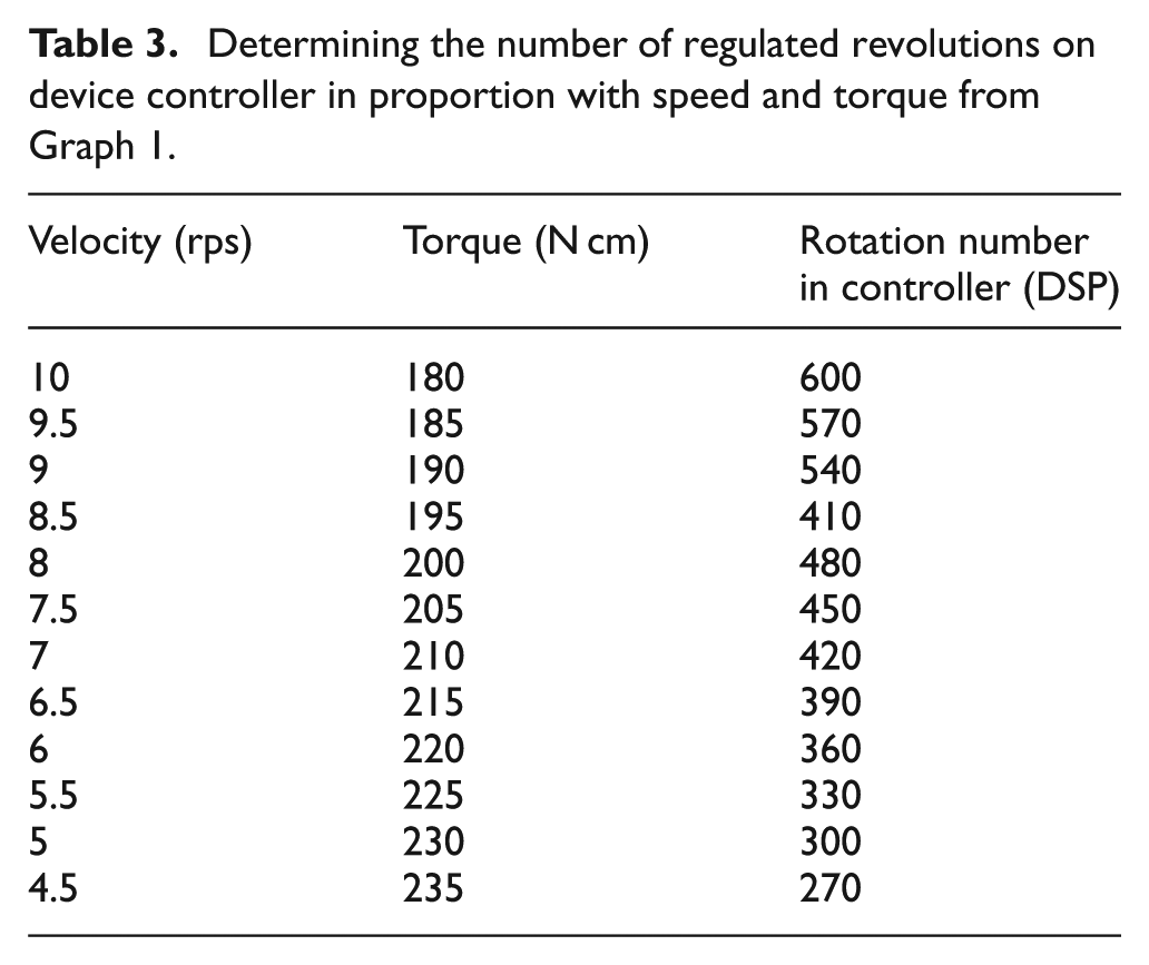
The revolution selection for the motion of step motor in accordance with the torque value is shown in Table 3. The maximum voltage is 48 with 300 W power.
Determining the number of regulated revolutions on device controller in proportion with speed and torque from Graph 1.
Results
The experimental conditions of test are shown in Figure 4. The controller used is a three-dimensional controller of Digital Sensor Processing (DSP). Ball screw is of 25 mm diameter, pitch of 5 mm and accuracy class C1 milled. 10
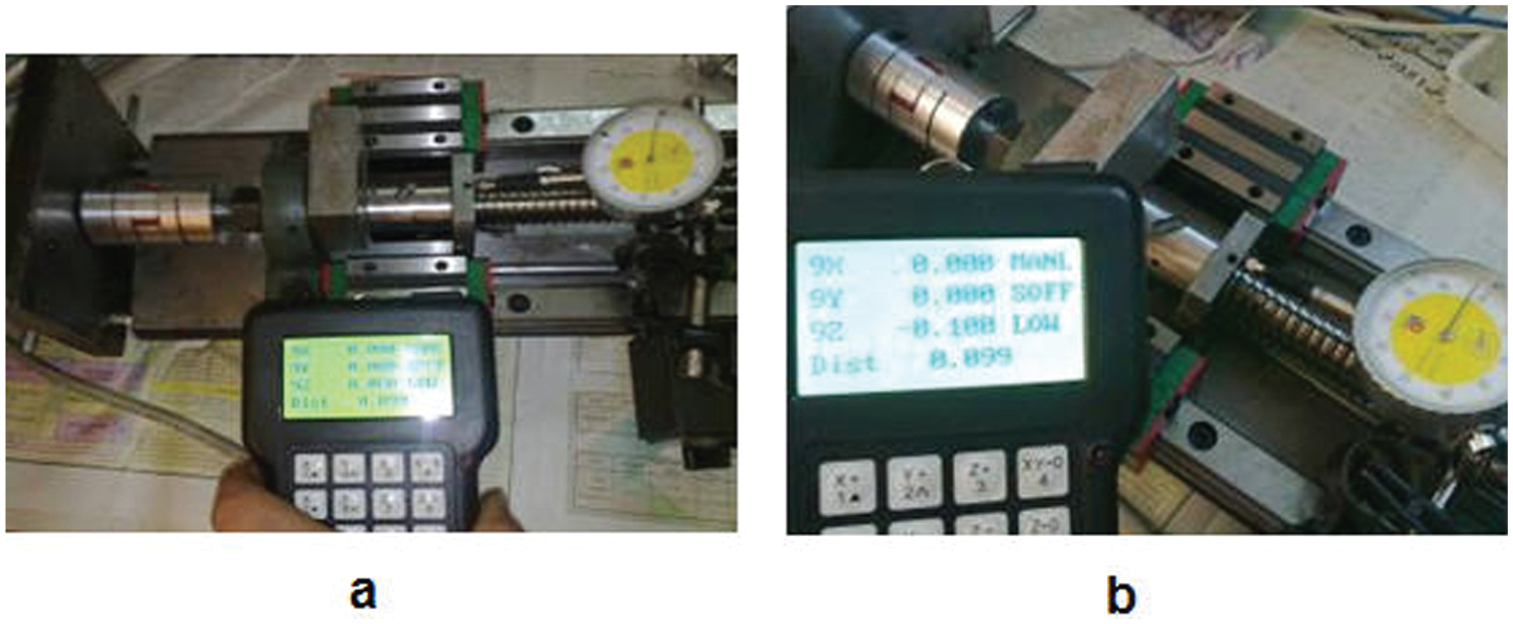
(a) Zero condition of the axle and (b) real value of elastic compression of elastomeric intermediate and the given value to the controller of the machine for movement.
In Figure 4, the setting to measure the elastic deformation of medium TPU is shown. Figure 4(a) shows the case where a steel block has prevented the ball screw knot from moving (knot locking) and is set by indicator watch in knot and blot axis as zero. This value is entered into controller as zero. Then, by distance mood, the value of 0.1 mm was given to controller, but as seen in Figure 4(b), indicator watch shows the value of 0.03 mm which returns immediately. Therefore, the elastic compression value is

This trend for stepper motors was performed to the speed of 600 r/min and nominal torque of 240 N cm at 12 times and the results are shown in Graph 2.
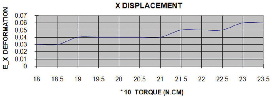
The results of experimental test for elastic deformation of coupling.
The three-dimensional model of elastomeric medium was created in ANSYS software and was elemented with element solid 185. The loadings were done on a part of medium compressively and total harness of the opposite side of medium. In Figure 5, the simplified model of finite element of elastomeric medium made of TPU is shown. The loading is shown in right bottom of the figure.
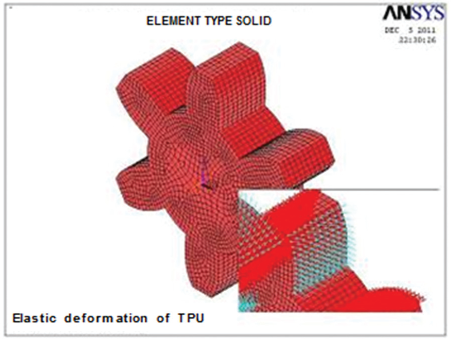
Element type and loaded model in ANSYS software.
Loading and solution were done statically, and the uniform distribution of the pressure from the torque conversion of stepper motors was applied on elastomeric medium teeth according to Graphs 2 and 3. For example, for a torque of 190 N cm, regarding the average diameter of medium at 3.1 cm, the compressive force of 20 N was applied on each tooth.
Medium deformation under the loading by ANSYS software.
In Figure 6, the elastic deformation of elastomeric medium for the torque of 220 N cm (20.9 N on each tooth) at 500 r/min of stepper motor is equal to 0.033 mm which has been shown in green.
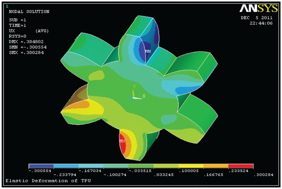
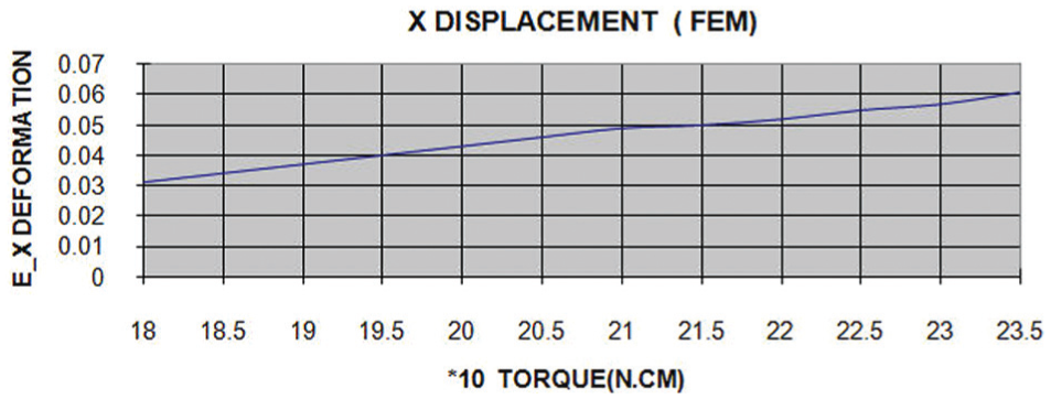
Elastic deformation of elastomeric intermediate along x-axle.
The elastic deformation value in X-axis versus stepper motor torque has been shown in Graph 3. According to the graph, at the torque of 190 N cm (equal to 20.9 N), the elastic deformation is 0.033 at X-axis

The important point is that external parts of medium teeth have become inclined, according to Figure 3; therefore, the sharp-edged parts are specified in blue. The green color in Figure 6, regarding the axial motion of ball screw, shows the deformation under the loading of 190 N cm in X–X direction to be 0.033 mm. This elastic compression is due to the given loading.
Conclusion
Using flexible couplings are considered common due to reduction and removal of nonlinearity in rotational axe. Mostly, accurate measuring devices undergo the locking situation exposed to tools or with barriers of knot and ball screw and the force from torque obtained by stepper motor which is harnessed by the base is transferred to bolt and coupling and due to elastomeric nature of medium, there is a possibility of elastic error.
To model and predict this error, simple Mooney–Rivlin binomial model was used. The experimental results with simulation of the case by a steel block to lock the knot showed that the instantaneous compression value of 0.03 mm is in consistence with 0.033 mm of simulated model by finite elements software. In addition, it was observed that, from the torque curve for two types of stepper motor, the elastic error increases with the increase in torque value in fixed revolution.
Footnotes
Declaration of conflicting interests
The author(s) declared no potential conflicts of interest with respect to the research, authorship and/or publication of this article.
Funding
The author(s) received no financial support for the research, authorship and/or publication of this article.