
Abstract
The use in motor vehicles of lightweight metals such as aluminium and titanium provides a high strength-to-weight ratio, thereby lowering overall weight and reducing energy consumption and CO2 emissions. Aluminium alloys have thus become an important structural material especially high strength and ultra-high strength alloys such as AW 7020. Many studies have shown that the presence of an aluminium oxide (Al2O3) thin film formed naturally on aluminium alloys is detrimental to welding. This article further investigates the specific effect of the Al2O3 thin film on welding AW 7020 alloy. An analytical experiment of welded AW 7020 alloy using a pulsed metal inert gas (MIG) robotic weld machine is carried out. Four specimens were cut, butt welded, and examined. The weld parameters included pre-weld cleaning of the Al2O3, pre-, and post-weld heat treatment. Al2O3 was removed by wire brushing; preheating was conducted at a temperature of 130 °C; and natural ageing was conducted by post-weld heating at 480 °C for 2 h, followed by quenching in water at 90 °C for 8 h, reheated, and sustained at 145 °C for 15 h. The result shows that the presence of Al2O3 layer appears not to be detrimental to the weld with new welding technologies, therefore suggesting that it is not necessary to grind off the Al2O3 layer before welding. This finding implies that welding costs can be lowered and weld quality improved when new welding technologies are applied in the welding of high-strength aluminium alloys.
Introduction
The use of lightweight metals in industrial applications has gained importance recently as a means of achieving a greener environment with low pollution. For example, studies1,2 show that the use of lightweight material in the construction of car bodies reduces weight, fuel consumption, and CO2 emissions. Welding of aluminium is considered challenging due to the inherent properties of aluminium alloys such as the high heat conductivity of aluminium alloys and the presence of an aluminium oxide (Al2O3) film that appears when the alloy is exposed to the atmosphere (which is detrimental to welding).3,4
Researches have shown that the presence of Al2O3 is detrimental to the welded piece and it also presents challenges for the welding process. The information gap of how detrimental is the Al2O3 to AW 7020 weld if new welding technologies that can prevent oxide inclusion are used exist.
This article discusses the Al2O3 layer formed on aluminium alloys exposed to air or moisture and its chemical properties. It describes the formation process and the composition of the two anodic layer films. Properties such as density, melting point, and thermal conductivity are presented. The advantages, disadvantages, and applications of Al2O3 are also presented. Its formation can be controlled to gain structural advantages and improved characteristics, for example, by adonisation.
The purpose or this research is to study the effect of Al2O3 on the mechanical properties of AW 7020. New welding technologies for aluminium welding are studied (because newer technologies are expected to provide faster weld speed, cheaper welding cost, and improved welding equipment efficiency), with focus on the effect of Al2O3 on the processes and how the welding process is used to produce acceptable welds despite the presence of Al2O3 film.
The experiments are carried out on an AW 7020 alloy using a robotised pulse MIG machine. The test pieces were cut across the weld, etched, and tested for hardness and tensile strength. As a contribution to the literature, this research provides facts on the effect of Al2O3 on AW 7020.
Al2O3 layer of exposed aluminium
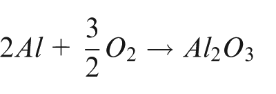
Aluminium is resistant to corrosion because aluminium, like all other passive metals, is covered with a continuous and uniform natural oxide film on exposure to an environment containing oxygen (as illustrated in Figure 1). The film is formed spontaneously in oxidising media according to the following reaction
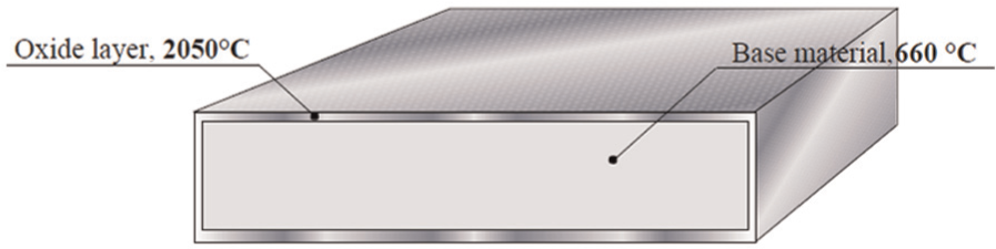
Schematic of aluminium (melting temperature of 660 °C) and its oxide layer (melting temperature of 2050 °C).
Formation process
Al2O3 layer forms immediately, within 1 ms or even less. 1 Al2O3 is a natural, non-uniform, thin, and non-coherent colourless oxide film made up of two superimposed layers of a thickness in the range of 4–10 nm. The oxidation reaction has a free energy of reaction 21,675 kJ. This is a very high oxidation reaction energy and explains why aluminium has high affinity towards oxygen. 1
The closest layer to the aluminium alloy is called the barrier layer and is illustrated in Figure 2. This layer has dielectric properties 2 and forms as soon as the aluminium alloy is exposed to an oxidising media. This layer consists of cells and pores that are generated due to reaction with the external environment. Attaining the final thickness can take several weeks or even months, depending on the physicochemical conditions of the environment. 3 This layer is less compacted than the barrier layer, and because of the presence of the pores, it reacts with the external environment during transformation.
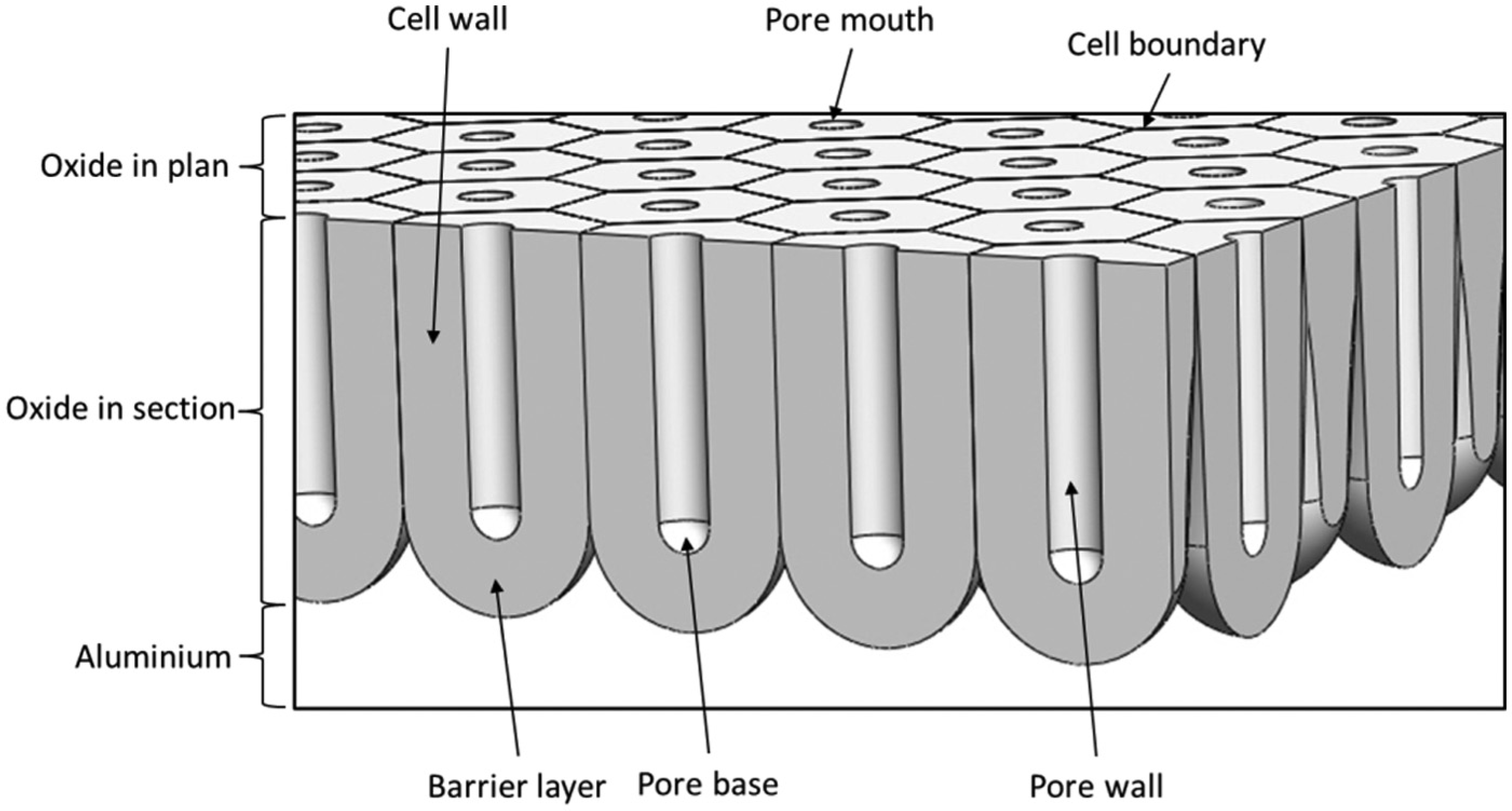
Schematic diagram of a cross section of a porous anodic film on aluminium showing the barrier, pore, and other principal morphological features.
Al2O3 characteristics and properties
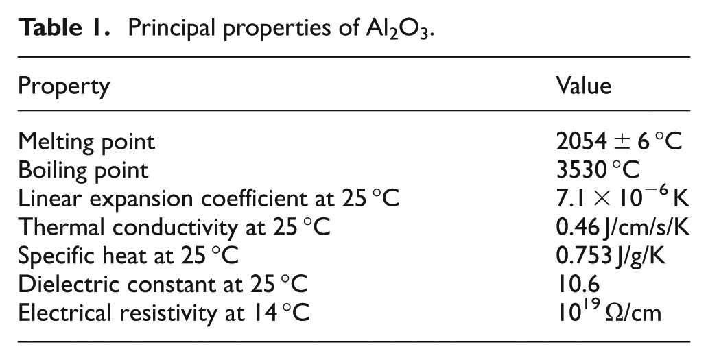
Amorphous alumina, chemically called Al2O3, forms at a temperature range of less than 50 °C to 60 °C and has a density of 3.40. Further principal properties are presented in Table 1. It is important to note that there is a difference in the density of the aluminium alloy and the Al2O3, so the Al2O3 film is under compression. This difference is responsible for the ability of the Al2O3 film to resist deformation without breaking and the excellent resistance during forming operations. 4 The mechanical and structural characteristics of Al2O3 layer are dependent on the oxygen partial pressure. 5 It is should be noted that the composition of the oxide film depends on the chemical composition of the aluminium alloy. Therefore, the thin film oxide layer is not the same for all classes of aluminium alloys. 6
Principal properties of Al2O3.
Al2O3 advantages, disadvantages, and applications
The Al2O3 layer brings both advantages and disadvantages to the use of aluminium in structures. It is advantageous as it is responsible for the corrosion resistance of aluminium alloys as presented in Table 2. Al2O3 allows for increased surface treatability of aluminium alloys using procedures such as anodising and painting. The presence of Al2O3 can cause weld defects such as incomplete weld fusion and weld porosity. Incomplete fusion describes a weld that does not completely merge or mix and porosity describes a weld in which gas bubbles are present in the weld.
Advantages, disadvantages, and applications of Al2O3.
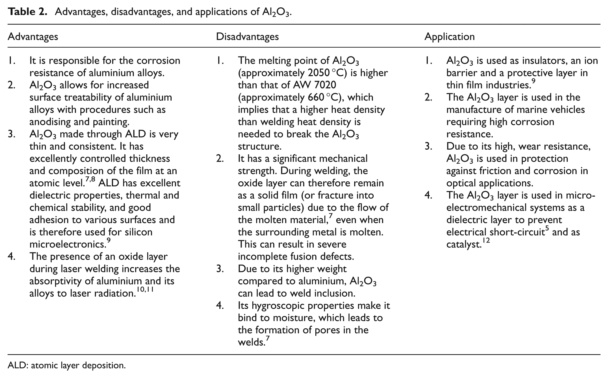
ALD: atomic layer deposition.
Al2O3 modification for structural advantage by anodising
The thickness of the Al2O3 layer can be varied to gain structural advantages by anodising. Anodising is a controlled corrosion process of aluminium alloys in alkaline and acidic electrolytes to attain a uniform continuous protective oxide film. 13 It employs the unique ability of amorphous alumina to build up an even porous morphology. It is important to mention that natural self-occurring Al2O3 is very thin (0.01 µm); anodising produces a higher thickness range (12–25 µm). 14 The advantages of anodising include fade resistance of structural aluminium alloys up to 50 years, 15 corrosion resistance, abrasion resistance, electrical insulation, unique decorative colours, adhesive bonding, decorative appearance, paint adhesion, improved lubricity, permission of subsequent plating, increased emissivity, surface flaws detection, and photographic and lithographic emulsions application possibility.16–18
The three main anodising processes are chromic anodising (in which the agent is chromic acid), sulphuric anodising and sometime referred to as mild adonisation (in which the active agent is sulphuric acid), and hard anodising (in which the agent is sulphuric acid, alone or in combination with additives). 19
New welding technology for aluminium alloys
Newer welding technologies are expected to provide better and cheaper welding processes, which make its important to be studied. Resistance welding (RW) can be used in the form of seam welds or spot welds. The fusion occurs due to the heat created by a flowing current through a resistance device for a given period of time while the materials to be welded are pressure pressed against each other. 20 The presence of Al2O3 on the pre-weld surface influences the total resistance across the weld electrodes. RW is thus a surface critical process; it is therefore recommended to remove the oxide before welding.
Friction stir welding (FSW) is a mechanical solid-state welding process that softens the material to be welded by the heat generated by friction between a rotating tool and the workpiece. There is no need to clean off the oxide layer prior to welding. However, flaws due to oxide inclusion can occur if the tool shoulder selected is oversize thereby sweeping surface oxide into the weld. The amount of oxide inclusion can be reduced by increasing the weld speed, resulting in low oxide layer disruption per millimetre. 21 Another new modification is laser-assisted FSW (in which the laser is mainly used for preheating) which has the additional advantage of using more simple and inexpensive machines, in addition to the reduction in tool wear and higher attainable welding speeds. 22
Low-energy arc (MIG) welding methods such as cold metal arc transfer (CMT) are a recent development of the MIG process. Low-energy arc welding uses the wire feed system to control the weld process. The wire is fed into the weld pool until the short circuit occurs, after which the feed direction is reversed and the feed wire is withdrawn. The wire feed is then fed forward again and the process begins anew. 23 The process utilises high-speed digital control systems to control the arc length, metal transfer, and thermal input on the workpiece. When integrated with pulsed MIG, it produces even better welds and the Al2O3 film is decomposed by the pulsed MIG process. 24
Laser welding employs the use of laser beams as a heat source for welding aluminium. Newer technological modifications involve the use of an active flux that improves the mechanical properties and appearance of the aluminium weld.23,25 In addition, dual beam lasers are used, producing better weld quality (deep penetration, surface smoothness, and high strength) compared to single beam laser welds. 26
Hybrid laser welding involves the use of a conventional arc welding process in combination with laser welding. The process utilises the advantages of both laser and arc [Metal inert gas (MIG) or Tungsten inert gas (TIG)] welding such as high process speed, low heat input, low thermal distortion, good gap bridging ability, and good process stability23,27 with high-precision welding. It is important to mention that in TIG welding process Al2O3 film decomposition occurs by cathode etching, however, it is still important with hybrid laser TIG welding processes to remove the Al2O3 layer just before welding.
Plasma arc welding (PAW) is a high-power-density weld method for aluminium that is advantageous for making deep welds. In addition to the general information in scientific and technical articles, aluminium welds are stabilised using direct current (DC) power and negative polarity; research has shown that stability can also be achieved using the alternating current (AC) power source. 23 Variable polarity plasma arc welding (VPPA) is a relatively new technology that uses advanced power supply to generate rapid switches from electrode positive (EP) to electrode negative (EN). With this technology, there is now the possibility of adjusting the EP and EN independently to enable good cleaning action (EP) and good penetration (EN). 28 Another modification to PAW is plasma MIG welding, which uses a coaxial MIG welding torch. Plasma MIG welding reduces spatter and fume formation and improves the weld bead appearance (the weld bead is flatter with deeper penetration in Al–Mg weld if the plasma current is increased). With plasma MIG welding, pre-weld Al2O3 layer removal is important. 29
Experimental procedure
The purpose of this experiment is to study the effect of the presence Al2O3 of layer on the mechanical properties of AW 7020. The experiment was carried out as butt welds of two samples each for the four weld experiment conditions (ECs) 1–4 with the weld parameters presented in Table 3. A robotised pulsed MIG machine was used to weld the specimen. The weld set-up is presented in Figure 3, respectively. A 4-mm AW 7020 plate was used as the workpiece. The air gap between the workpiece was 3 mm. A copper backing was used. Pure argon (99.5%) shielding gas supplied at a flow rate of 15 L/min was used. A 1.2-mm-diameter Elga AlMg5 filler material was supplied at 9 m/min. A nozzle distance of 15 mm and a welding speed of 7.5 mm/s were used. The weld torch was inclined at 15° to normal and the weld direction was such that the torch is pulling. An average current of 140 A and an average voltage of 22.7 V were used in all the experiments.
AW 7020 weld experiment parameters.
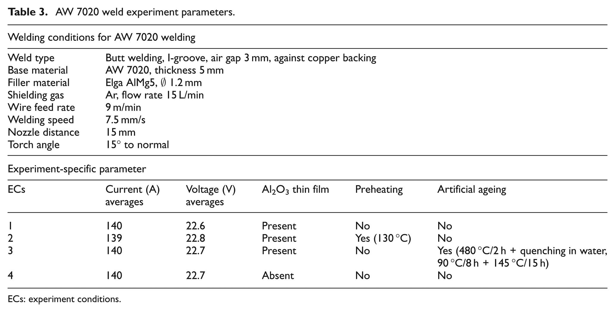
ECs: experiment conditions.
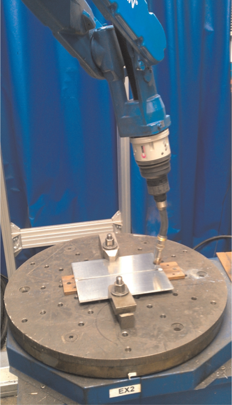
AW 7020 weld set-up.
The test was carried out in the welding workshop, in a well-controlled atmosphere and at room temperature. The samples for the four different EC were cut, welded, and examined. In EC 1, the weld was carried out without pre-weld cleaning of the Al2O3 in the absence of pre- and post-weld heat treatment. In EC 2, the weld was conducted without the removal of Al2O3. However, the workpiece was preheated at a temperature of 130 °C within the recommended preheating temperature and close to the upper limit. 30 The oxide layer in EC 3 was not removed before the welding. No preheating was carried out but natural ageing was conducted by post-weld heating at 480 °C for 2 h, followed by quenching in water at 90 °C for 8 h, and finally, reheating and maintaining the workpiece heat at 145 °C for 15 h. The Al2O3 layer in EC 4 was removed and no preheating or artificial ageing was carried out. In order to investigate the effect of Al2O3 on the mechanical properties, the samples were examined for ultimate yield strength (YS), tensile strength, elongation, and hardness values. Macrographs were taken to evaluate the degree of weld defects present, if any.
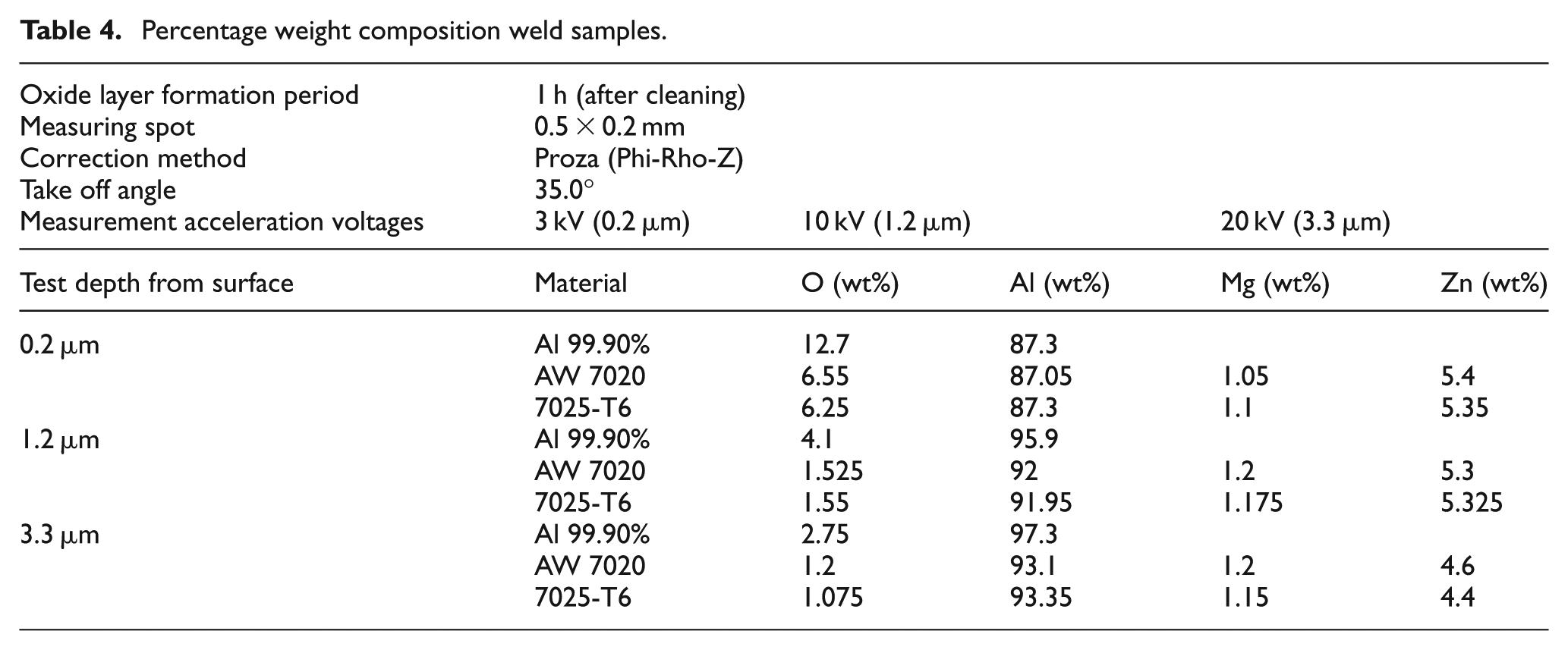
Further experiments were carried out on the welded sample to study the composition of Al2O3 layer at different distances from the alloy surfaces. A sample of over 99% pure aluminium alloy (1xxx series), AW 7020, and 7025-T6 were placed to a thermo scientific ultra dry Silicon Drift Detector (SDD) energy-dispersive X-ray spectroscopy (EDS). Three weld samples were pre-cleaned and then exposed to atmosphere for 1 h. The samples were then tested for the presence of Al2O3. Each sample was tested at a depth of 0.2, 1.2, and 3.3 µm. For each depth, four measurement spots of 0.2 × 0.5 mm were selected and each significant chemical content was analysed; the results presented in Table 4 are based on the averages.
Percentage weight composition weld samples.
Result
The mechanical properties of the welds were observed and the results are presented. The result consists of tensile test (that provides information on the YS, ultimate tensile strength (UTS), and elongation at fracture), hardness test, and macrograph examination.
Tensile tests
The tensile test bar graph in Figure 4 presents a comparison of the YS (Re/N/mm2), UTS (Rm/N/mm2), and elongation at fraction in A/%. The y-axis is measured in units and the x-axis represents the averages of the four different ECs and the control condition. The YS values represent the amount of force the welded AW 7020 can resist before plastic deformation. The UTS value shows the amount of force needed to break the weld, and the elongation shows how far the weld will stretch before breaking.
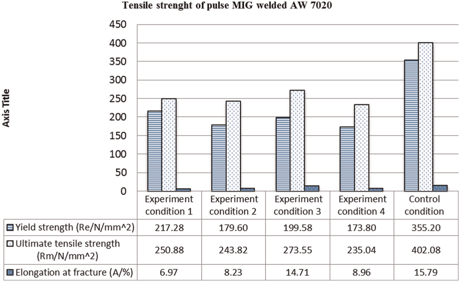
Tensile strength of welded AW 7020.
The tensile test measures the YS, which is the stress value at which welded specimen begins to deform plastically and cannot return to its original position. It is used in this experiment to express the load bearing capacity of the weld just before plastic deformation. The higher the YS, the more desirable is the weld. Based on the YS values, EC 1 is the best weld while EC 4 is the worst weld, which is due to the effect of removing the Al2O3 layer thereby increasing the amount of weld heat input. As seen in EC 2, preheating also seems to reduce the YS while artificial ageing appears to improve the YS in EC 3.
The UTS is used to present the maximum tensile loading the weld can be subjected to before failure. The higher the UTS, the better the weld is from the load bearing perspective. In these experiments, EC 3 produced the highest UTS value of 273.55 Rm/N/mm2. This seems to be due to the effect of artificial ageing. EC 1 has the next high, which seems to be due to the low heat input to the workpiece due to the presence of Al2O3. EC 2 has the next high value, which suggests that workpiece preheating reduces the UTS values. The least UTS value is in EC 4 which suggests that the removal of Al2O3 layer reduced the UTS.
Elongation at fracture expresses the ratio as a percentage of the final length to the original length to which the area of the specimen stretches just before failure. The elongation shows how brittle or ductile the weld specimen is. If the elongation is low, the weld piece will be brittle, and therefore, it can easily crack or break, for example, brittle ceramic cracks easily when subjected to tensile loading. On the other hand, if the elongation value is high, the specimen is ductile and can be plastically deformed. In many aluminium welds, it is desirable to have high elongation values. The best weld is usually case specific based on the mechanical or metallurgical properties of the weld demanded by the application. For example, aluminium welds that are designed to carry torsion loads such as shafts are supposed to be rigid with minimal elongation. On the other hand, structural aluminium beams are expected to have elongation so they do not break suddenly. EC 3 has the highest elongation values which suggest that artificial ageing increased the malleability of the workpiece. The next high elongation value is in EC 4 which suggests that the absence of Al2O3 increases elongation in comparison to EC 1.
Hardness test
The hardness profile graph (Figure 5) presents the hardness values of the profile across the weld interface (WI). The hardness profile shows how much the hardness deviated from the base material (BM) into the unmixed zone (UMZ) and vice versa. The y-axis represents the hardness value (HV3) while the x-axis represents the distance in millimetre from a common reference in the BM to the weld centre. It is important to mention that 0 in the x-axis is located in the BM and the scale increases towards the UMZ.
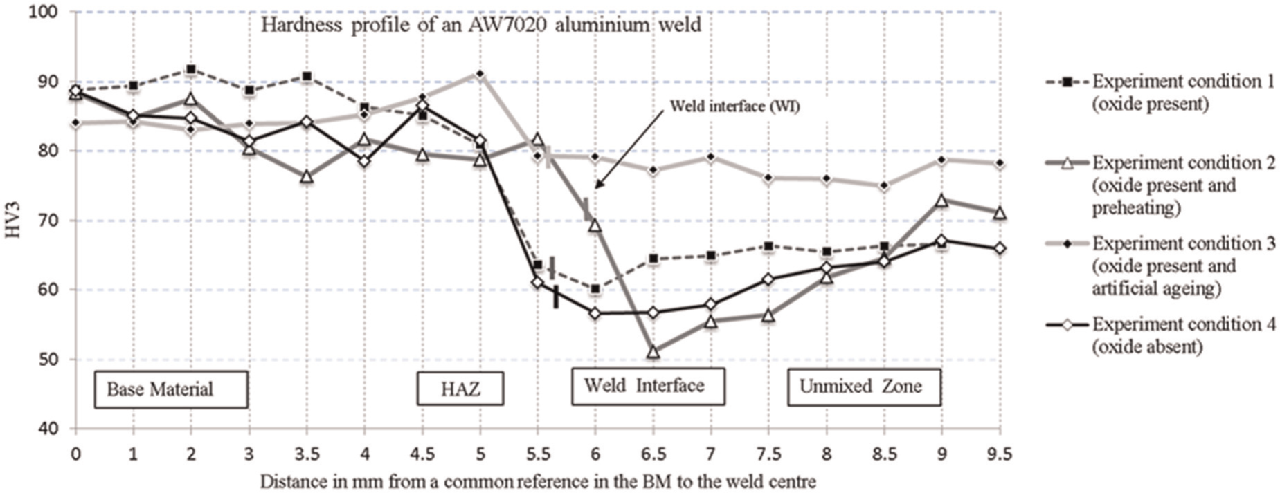
Hardness profile of welded AW 7020.
The hardness test is done using a diamond tip indenter to create indentations on the weld cross section. The indenter has two diagonals, which are measured and used to determine the hardness value on the HV3 scale. The indenter carries a load that is enough to create an indentation on the alloy. The hardness of the material determines the material resistance against the indenter. This implies that the softer the material (aluminium alloy), the deeper the indents and the longer the diagonals of the indents. The depression caused by an indenter can be seen in Figure 6.
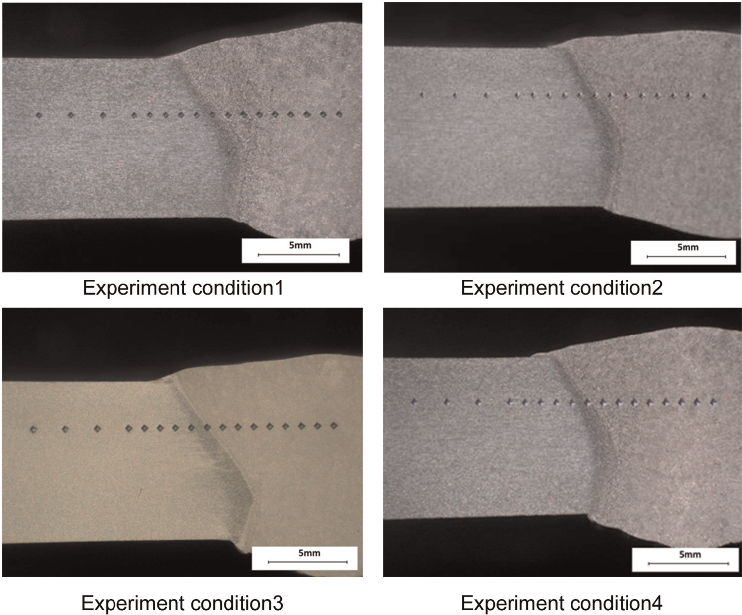
Macrographs of welded AW 7020.
In Figure 5, the average hardness values are denoted by the nodes on the line graph. The hardness from the BM to the weld centre line should have minimal fluctuation. The WI denotes the point at which the weld fusion line appears. It can be seen that the greatest hardness fluctuation is around the heat-affected zone (HAZ) and the WI, which are usually the areas more prone to structural failure. EC 3 (Figure 5) has the best hardness profile of the four ECs while EC 2 has the worst hardness profile, especially across the WI.
Macrograph analysis
The macrograph samples of each EC are presented in Figure 6 using 10× objective lens to present the interaction between the weld pool and the BM across the WI. These pictures are used to present weld defects such as porosity and cracks, if there are any. In addition, they also show the HAZ and the location of the WI from the weld centre line. The macrograph samples also present the bead profile. It is important to mention that the indentations in Figure 6 are made by the hardness testing machine and the position of the indents from the plate surface is approximately the same for all the experiments. In the four ECs, it appears that there are no cracks or porosity on the macro scale which suggest that the welds are acceptable.
EDS
The EDS result is presented in Table 4 showing the test parameters. The measurement acceleration voltages 3, 10, and 20 kV represent the calculated depths of 0.2, 1.2, and 3.3 µm. At 0.2 µm depth, the presence of oxygen is highest in all the samples and lowest at 3.3 µm. The oxygen content in addition to the other elements in AW 7020 and 7025-T6 are relatively close. This may be due to the same alloy series they belong to in the classification. The classification is based on the chemical composition of the alloy.
Discussion
The effect of Al2O3 on the AW 7020 weld is based on the hardness profile of EC 1 and EC 4, which are similar (Figure 5). However, the hardness values of EC 1 are higher than EC 4. The presence of Al2O3 layer in the weld process (EC 1) increased the YS by 20% and the UTS by 6% but reduced the elongation by 29% (compared to EC 4). This result shows that when Al2O3 layer is not removed before welding, improved hardness of AW 7020 weld was attained (it is important to note that there are no weld defects such as porosity due to oxide inclusion in the weld pool). The question therefore arises whether the higher strength could result from the reduced heat that gets into the weld pool due to the heat resistivity of the Al2O3 layer in addition to the suspected absence of chemical interaction of Al2O3 layer during the weld (due to the welding technology and weld parameters). This can be clarified by further multiple experiments. However, it is important to mention that if there is a chemical reaction in which Al2O3 layer is present in the weld (causing porosity), the mechanical properties will be lower.
The effect of pre-weld heat treatment on the AW 7020 weld is detrimental to the weld comparing EC 2 to the other three in Figure 5. The hardness profile across the weld in EC 2 is more uneven with sharp fluctuations in hardness values. For example, there is a sharp decrease in the hardness value from 81.7 to 51.1 HV across the WI. This is usually a crack failure point in the weld piece. In EC 2, the WI is closer to the UMZ (narrower HAZ) which is better when narrower weld seam is desired; however, it reduced the hardness values. Preheating reduced the YS by 17% and UTS by 3% but increased the elongation by 17% (Figure 4).
The effect of artificial ageing on the AW 7020 weld is that artificial ageing relatively smoothens the hardness profile, in addition to increasing the hardness values in the HAZ, WI, and UMZ. Comparing EC 1 and EC 3, the hardness value at the WI increased from 63.6 to79.3 HV (Figure 5). Artificial ageing reduced the YS by 8% but increased the UTS and elongation by 9% and 110%, respectively (Figure 4). It therefore suggests that artificial ageing improves the mechanical properties of welded AW 7020 provided there are no weld defects. Based on the macrographs, the welds in this study appear to exhibit no defects (Figure 6)
The necessity of pre-weld Al2O3 removal is examined in this study. Acceptable welds were achieved without pre-weld removal of the Al2O3 layer (Figure 6, EC 1-3) using a pulsed MIG welding process. This may be due to the low chemical interaction of Al2O3 with the weld pool as the EDS result shows that the oxygen content of Al2O3 in AW 7020 is about 50% lower than in pure aluminium. It therefore suggests that with new welding technologies such as pulsed MIG and FSW, it is not necessary to remove naturally formed Al2O3 layer before welding high-strength aluminium (HSA) alloys.
Good welds may have been attained due to the lower amount of oxygen present on the surface of AW 7020 compared to pure aluminium. This suggests why HSA alloys have lower corrosion resistance in comparison to pure aluminium. It is important to mention that based on the literature review, the effect of Al2O3 in aluminium welding seemed to have been active in the 1940s until 1960. There appears to be a break in the interest for this research, as it seems to have then picked up again from 1990 until date, which suggest that there was a lost in interest during the 1970s and 1980s.
Conclusion
This study was carried out to investigate the effect of the Al2O3 film on the mechanical properties of HSA alloys using pulsed MIG-welded AW 7020 as a case study. The structural formation of the Al2O3 layer was briefly explained; the structure varies depending on the class of aluminium alloy. The characteristics and properties of the Al2O3 layer were discussed, and the study presented how the Al2O3 structure can be modified for structural advantage. A brief description of new welding technologies used for aluminium alloys was presented. In addition, weld defects in aluminium welds associated with Al2O3 were also presented. Based on the literature review and experimental study, the following conclusions can be made:
The experiment indicates that pre-weld heat treatment of AW 7020 alloy is detrimental to the mechanical properties of the weld because it reduces the mechanical properties of the weld.
Artificial ageing of AW 7020 welds improves the mechanical properties, including the hardness, tensile strength, and ultimate YS. Therefore, it is suggested that post-weld heat treatment is advantageous in HSA alloys.
Acceptable welds are attainable without pre-weld cleaning of the Al2O3 film. It is therefore suggests that removal of the Al2O3 is not necessary when new welding technologies such as the pulsed MIG process are used on HSA alloys.
The presence of the Al2O3 film is not detrimental to the mechanical properties of HSA alloy welds if there is no chemical interaction. It suggests that new weld technology that prevents Al2O3 chemical interaction during weld that can cause weld porosity and other weld defects are advantageous.
The chemical composition of Al2O3 varies across the different classes of wrought aluminium alloys. This suggests that the structure is not the same in all the aluminium alloys but similar in each aluminium alloy classes. In addition, it suggests that the structure is also dependant on the chemical composition of the parent metal.
Footnotes
Declaration of conflicting interests
The author(s) declared no potential conflicts of interest with respect to the research, authorship, and/or publication of this article.
Funding
The author(s) received no financial support for the research, authorship, and/or publication of this article.