
Abstract
Recently, tubular-type coupled torsion beam axle, which is a component of the automotive rear suspension systems, has been developed by using ultra-high strength steel. It is manufactured by hot stamping process to enhance the strength and reduce springback. The hot stamping process is classified as a direct method and an indirect method according to forming sequence and quenching method, so-called die quenching or water quenching. Each of these methods has limitations in the aspect of dimensional accuracy and strength. Hybrid quenching is a new quenching method which sprays water to the tube directly in addition to die quenching. In this study, direct hot stamping with hybrid quenching was applied to produce an automotive tubular coupled torsion beam axle of ultra-high strength steel. This study proposes a simulation method of hybrid quenching for tubular beam and the hybrid quenching method was evaluated experimentally. Finally, the proposed hybrid quenching method has been found very effective in reducing the cooling time and thermal deformation.
Introduction
In accordance with vehicle safety and environmental regulations, numerous research activities have been performed for the structures, materials, and processes related to weight reduction, and the application of ultra-high strength steel (UHSS) has been regarded as one of the most effective weight reduction methods. However, it is not easy to apply the UHSS to the automotive components due to quality concerns such as cracking and springback that could happen after cold forming. Hot stamping process can solve these problems due to inherited low elongation and high yield strength features of the UHSS.1–4 As the ultra-high strength of steel plates is achieved through hot stamping, the UHSS plates are considered to be very effective for weight reduction and their application range has quickly and widely expanded to vehicle body parts as well as chassis parts.5,6
In the hot stamping process, a blank or a pre-formed part using boron steel with a tensile strength of 500–600 MPa is heated to approximately 1203 K (930 °C). To avoid significant heat loss, the heated blank or pre-formed part is quickly transferred to the press and subsequently strengthened above 1400 MPa through press hardening or rapid quenching.7,8 The hot stamping process is typically classified as direct and indirect hot stamping. In direct hot stamping, a blank is formed and cooled simultaneously after heating. In indirect hot stamping, the pre-formed part is then heated and cooled after forming a blank at room temperature.9–11 Additionally, depending on the cooling type, the quenching method can be classified as die (indirect) quenching and water (direct) quenching. Figure 1(a) shows die quenching where the heat transfer occurs between the heated part and the die with cooling channels. Figure 1(b) and (c) shows water quenching where the heated part is fixed by a jig and either cooling water is sprayed or the part is immersed in a water tank.
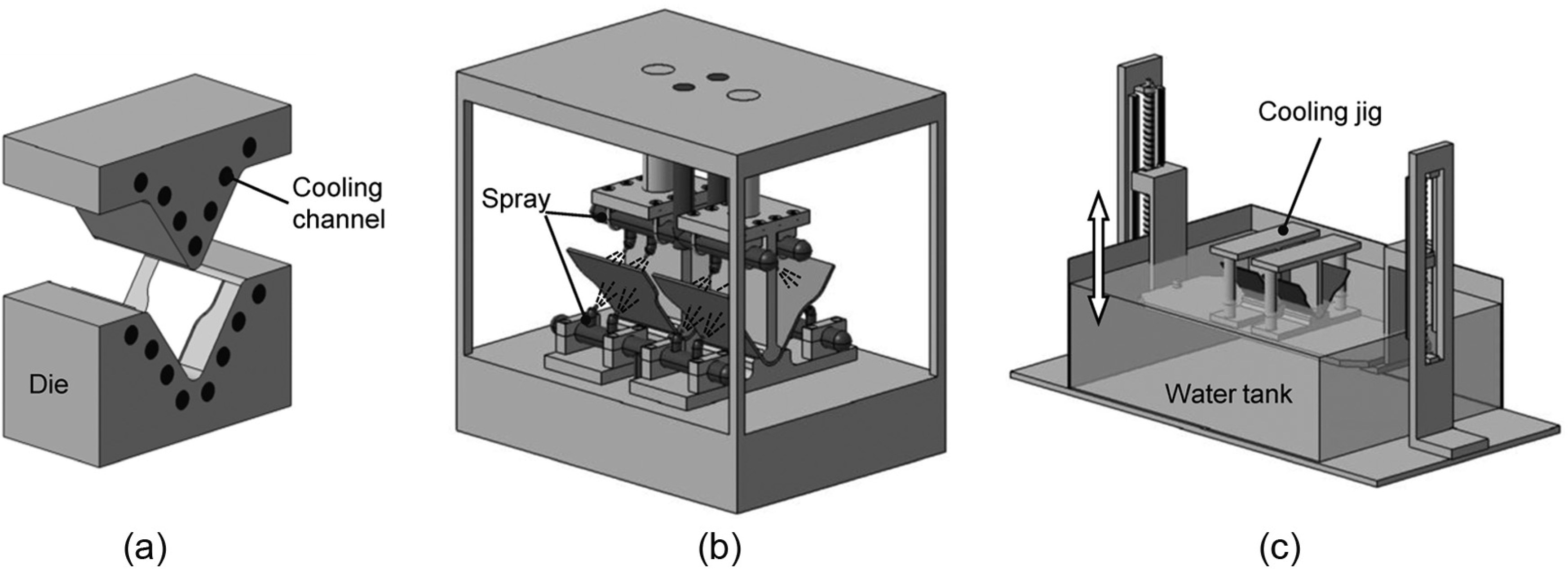
Comparison between die and water quenching: (a) die quenching, (b) water spray, and (c) water immersion.
Direct hot stamping with die quenching has simultaneous forming and cooling steps. For indirect hot stamping, water quenching is typically chosen to reduce the production cycle time. For automotive parts, direct hot stamping with die quenching is largely used for relatively thin parts that are less than 2.0 mm thick. Indirect hot stamping with water quenching is mainly applied for relatively thick chassis parts. This is because as the material becomes thicker, it is more difficult to quench it by indirect cooling through cooling channels inside the die. Meanwhile, different from die quenching, the cooling water in water quenching touches the product directly, and thus, the cooling effect is superior, but it is difficult to control the thermal deformation caused by phase transformation during water quenching. 12 These problems must be solved by selecting the appropriate methods considering not only the formability depending on the part shape but also the cooling effect depending on the material thickness.
As these hot stamping processes are widely used, various studies are in progress to solve problems such as thermal deformation and low productivity. Specifically, for tubular beams of the rear coupled torsion beam axle (CTBA) shown in Figure 2, 13 much research has been recently carried out on the weight reduction effect by improving the durability and component integration, and high strengthening through hot stamping of the tube material. 14
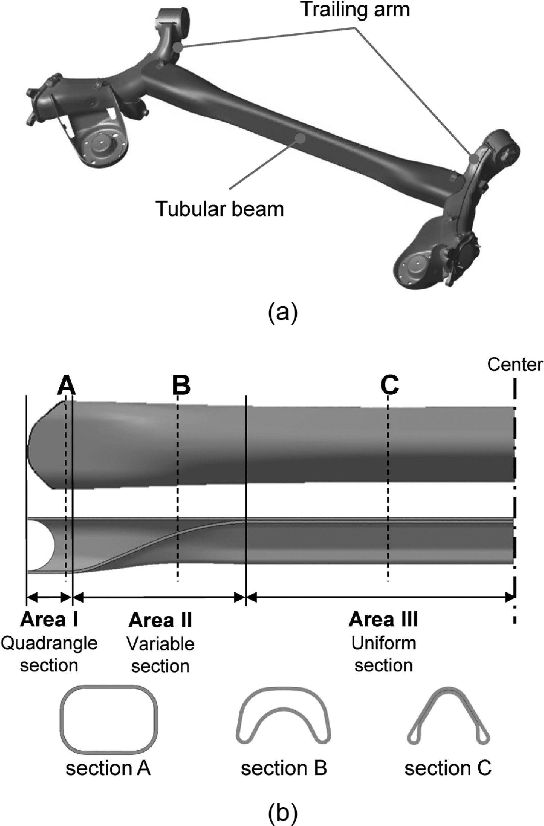
Rear coupled torsion beam axle (CTBA): (a) geometry of tubular torsion beam axle and (b) typical cross-sectional profile of tubular beam.
Lee et al. 15 designed a cooling jig to minimize shape changes caused by phase transformation during water quenching through finite element (FE) simulation, but the result was not experimentally verified. Park et al. 16 experimentally obtained the heat transfer coefficient for indirect hot stamping of a tubular beam and applied it for analytical verification. As a result, if a separate product fixing jig was used, it could decrease the deformation of the tubular beam. Kim et al. 17 researched the design of effective quenching channels depending on the material thickness for direct hot stamping, and Yoon et al. 18 researched thermal deformation of the product depending on the cooling duration time. Zhang et al. 19 proposed a new method using an extruded V-shaped tube that essentially eliminates the vertical pressing process in conventional hot stamping. Neubrand 20 applied indirect hot stamping using the tailor rolled tube (TRT) for weight reduction of a tubular beam.
As mentioned above, although it is difficult to solve thermal deformation problems in water quenching, research has been focused on indirect hot stamping with water quenching.
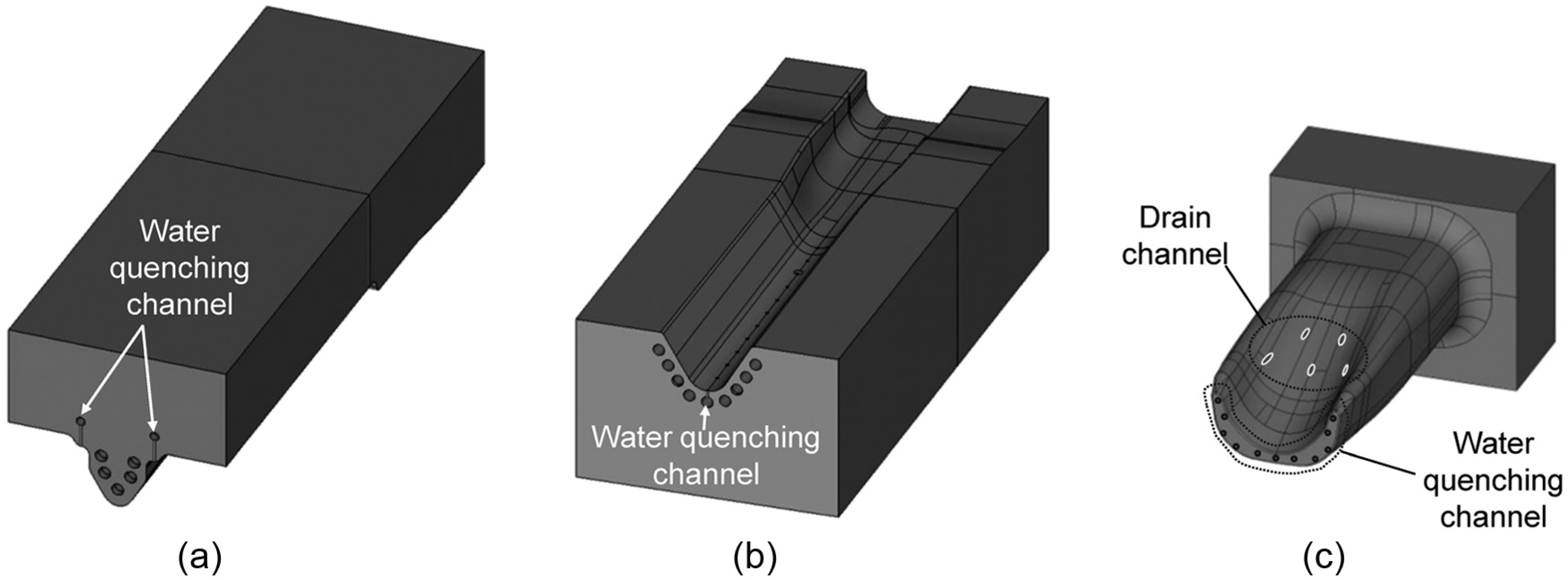
If the die quenching is applied to a tubular beam, it is difficult to get the full martensite phase and its corresponding high strength of 1500 MPa due to the limited cooling capacity21,22 and the contact conditions.23,24 Figure 3(a) shows a schematic drawing of a die quenching system. Figure 3(b) and (c) shows the horizontal and vertical sections of the die after forming a tube with 3.2 mm thickness, respectively. As shown in Figure 3(b), in the area of uniform cross section (Area III in Figure 2(b)), the thickness of the tubular beam becomes 6.4 mm between the upper and lower dies. Therefore, the cooling time must be prolonged because thick material should be cooled sufficiently after forming. Furthermore, it is difficult to make a die because to obtain sufficient cooling capacity, the number of cooling channels should be increased or the cooling channels should be close to the die surface in contact with the tubular beam. In addition, the desired mechanical properties cannot be obtained and thermal deformation can be larger due to the non-contact areas between the die and tubular beam, as shown in Figure 3(b) and (c).
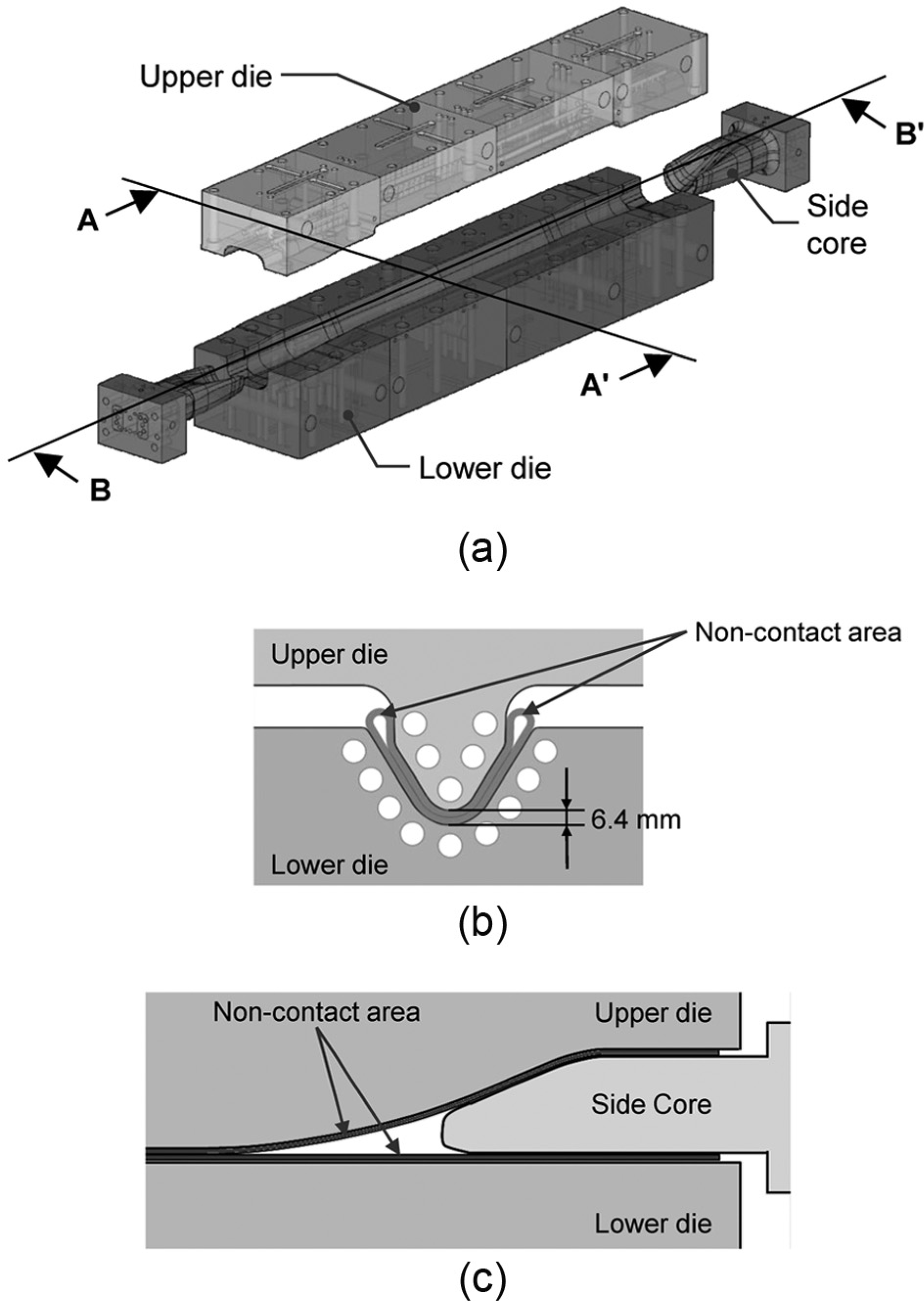
Typical die quenching system for tubular beam: (a) schematic drawing of die quenching system, (b) section AA′ after forming, and (c) section BB′ after forming.
In this article, a hybrid quenching method that allows simultaneous die and water quenching for a tubular beam is proposed. The effectiveness of this method is verified experimentally by comparison with die quenching based on the temperature distribution, phase transformation, mechanical properties, and thermal deformation. Additionally, FE simulation results were obtained by varying the temperature conditions of the die quenching area (DQA) and water quenching area (WQA) and were compared with the temperature distribution of the actual tubular beam depending on the variation in the cooling time.
Experiments and FE simulation
Experimental conditions
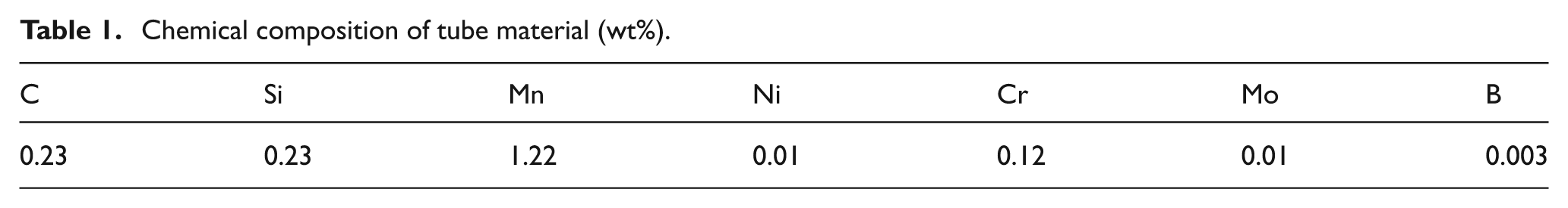
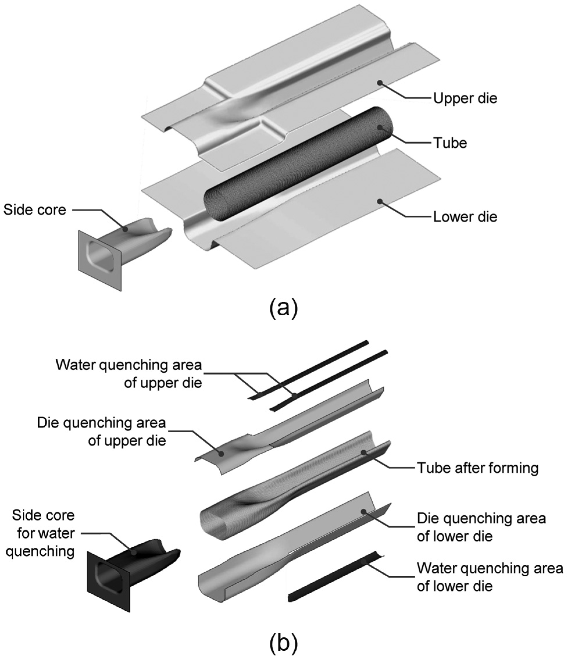
The tube material utilized in this study is boron steel PHT1470 (POSCO Inc., Korea) and its chemical composition is shown in Table 1. PHT1470 has almost the same chemical composition as the 22MnB5 most commonly used in hot stamping. The geometry of the tube has an outer diameter of 90 mm, length of 1150 mm, and thickness of 3.2 mm. The tube is washed and dried to eliminate any impurities such as oil or water and is heated to 1203 K (930 °C) in a furnace to transform it to a homogeneous austenitic phase. The heated tube is then transferred to the inside of the hybrid quenching die within 7 s using a high-speed feeder and is formed and quenched sequentially by a hybrid quenching die. A hydraulic servo press with hydraulic cylinders for controlling side cores is used for the experiment. The force applied during the forming by the press is 5500 kN, and the velocities of slider and side cores are 175 and 115 mm/s, respectively. The structure of the hybrid quenching die is shown in Figure 4. As shown in Figure 4(a), the upper die has five indirect die quenching channels with a diameter of 11 mm. It also contains two direct water quenching channels, which can directly spray cooling water at a regular interval to a non-contact area of the tubular beam (Figure 3(b)). The lower die in Figure 4(b) has eight die quenching channels and one water quenching channel. As shown in Figure 4(c), both side cores of the lower die have 11 water quenching channels for cooling a non-contact area in Figure 3(c). 25 Each side core has five drain channels for eliminating internal pressure. Once forming and quenching are completed, shot peening is executed to remove oxide scale 26 and provide residual compression stress to the surface. Finally, laser cutting is executed to match the trailing arms. In this study, actual tests were carried out for two samples per process, and they were performed four times to ensure reliability for each case of die quenching at 22 s and hybrid quenching at 13, 16, 19, and 22 s.
Chemical composition of tube material (wt%).
Design of cooling channel for hybrid quenching: (a) upper die, (b) lower die, and (c) side core.
FE model and conditions
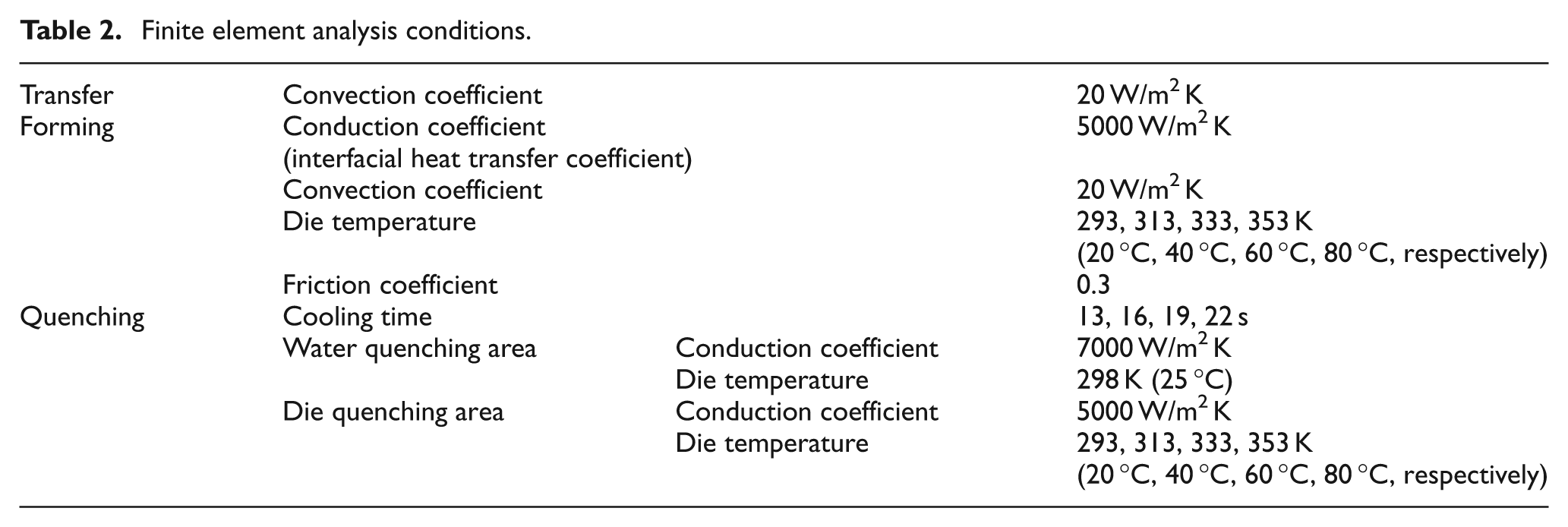
FE simulation was implemented to investigate the temperature and phase transformation of the tubular beam in accordance with the cooling time in the die. The commercial software PAM-STAMP 2G was used for the thermo-mechanical simulations, which are composed of three processes: the transfer step, the forming step, and the quenching step. The FE model is shown in Figure 5 and the simulation conditions are shown in Table 2. The material parameters of boron steel (22MnB5) such as Young’s modulus, Poisson’s ratio, specific heat, and flow stress were taken from PAM-STAMP material library. 27 The tubular beam was constructed with 26,544 shell elements and the upper die, lower die, and side cores were modeled as rigid bodies. The initial phase of the tube material was assumed to be 100% austenite and the initial temperature was 1203 K (930 °C) and room temperature was 293 K (20 °C). In the transfer step, heat transfer simulation was only performed. The transfer time was 7 s and convection was only considered during transfer. In the forming step, as shown in Figure 5(a), the forming simulation was performed to obtain the deformed shape and temperature distribution of the tubular beam. Both the convection and conduction were considered during the forming. In the quenching step, as shown in Figure 5(b), heat transfer simulation was performed. As shown in Figure 5(b), to consider the die and water quenching effect, elements of the quenching dies were reconstructed from the resulting shape of the tubular beam after the forming simulation. Specifically, the WQA and DQA contacted the tubular beam to allow thermal conduction. To determine the appropriate simulation conditions, different die temperatures of the WQA and DQA were chosen. The WQA temperature was fixed at 298 K (25 °C), and the DQA temperatures were 293, 313, 333, and 353 K (20 °C, 40 °C, 60 °C, and 80 °C, respectively).
FE model for hybrid quenching simulation: (a) forming step and (b) quenching step.
Finite element analysis conditions.
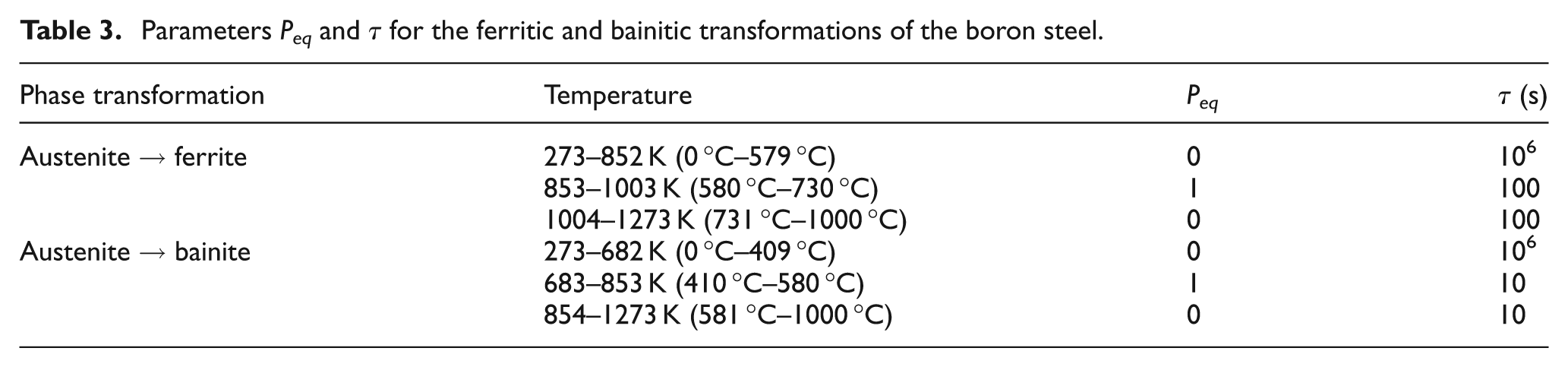
To consider the phase transformation effect, diffusion and martensitic transformation kinetics were applied. The volume fraction of pearlite, ferrite, and bainite transformed from austenite is separately defined by the diffusion transformation model proposed by Leblond and Devaux 28 (Leblond kinetics). This model can be extended to include the possibility of isothermal kinetics of the Johnson–Mehl–Avrami type, 29 as well as the influence of austenite grain size. 30 The Leblond model is expressed by the following equation
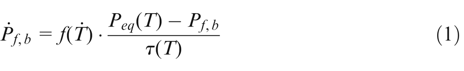
where the subscripts f and b refer to ferrite and bainite, respectively.
Parameters Peq and τ for the ferritic and bainitic transformations of the boron steel.
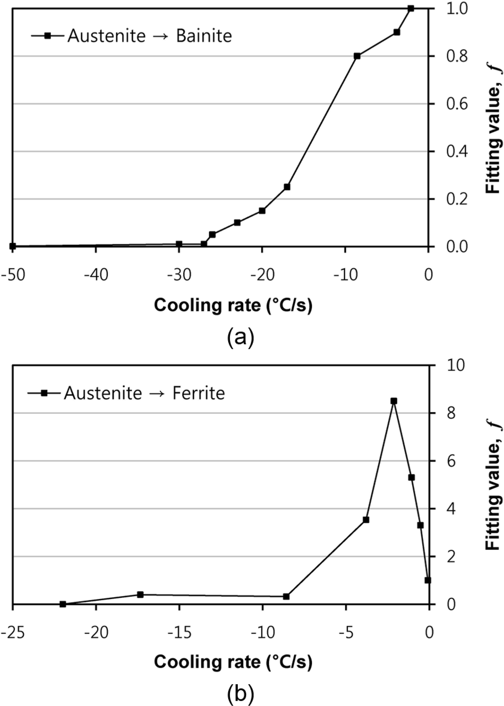
Fitting value according to cooling rate: (a) bainitic transformation and (b) ferritic transformation.
The martensitic volume fraction,
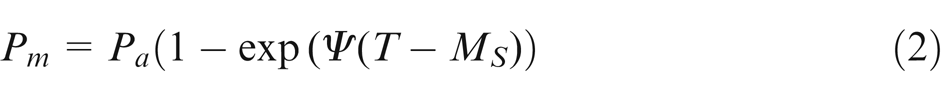
where
In the hot stamping simulation, the total strain increment,
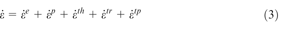
where
Results and discussion
Temperature distribution
The temperature of the initial tube was 1203 K (930 °C) and decreased to 1123 K (850 °C) during the transfer simulation. There were no fracture or wrinkle problems during forming simulation. Figure 7 shows the temperature distribution results of the tubular beam in accordance with the cooling time for hybrid quenching simulation. The minimum temperature area was inside the tubular beam, which was directly cooled by water spray from the side core. As the cooling time passed, the minimum temperature converged to the die temperature. Additionally, the results for Cases 2, 3, and 4 show that when the DQA temperature was higher than the WQA temperature, the minimum temperature of the tubular beam converged to the WQA temperature and the maximum temperature converged to the DQA temperature.
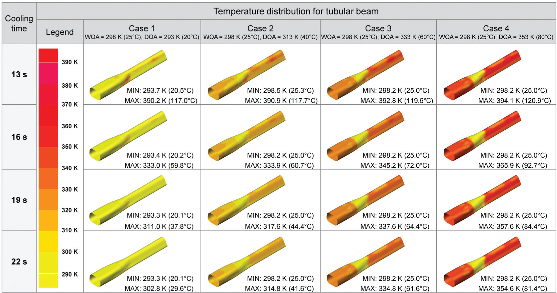
Analysis results of temperature distribution according to cooling time.
As shown in Figure 8, actual tests were carried out for two samples per process. Figure 8(a) shows the state after loading the heated tubes onto the die, and Figure 8(b) shows the state after completing forming and quenching. The temperatures of the tubes and tubular beams at the conditions of Figure 8(a) and (b) were measured using a thermal imaging camera, and the results are presented in Figure 9. In addition, for each condition, the temperature was measured from the upper center of the product in the horizontal direction, and the results are shown in Figure 10.
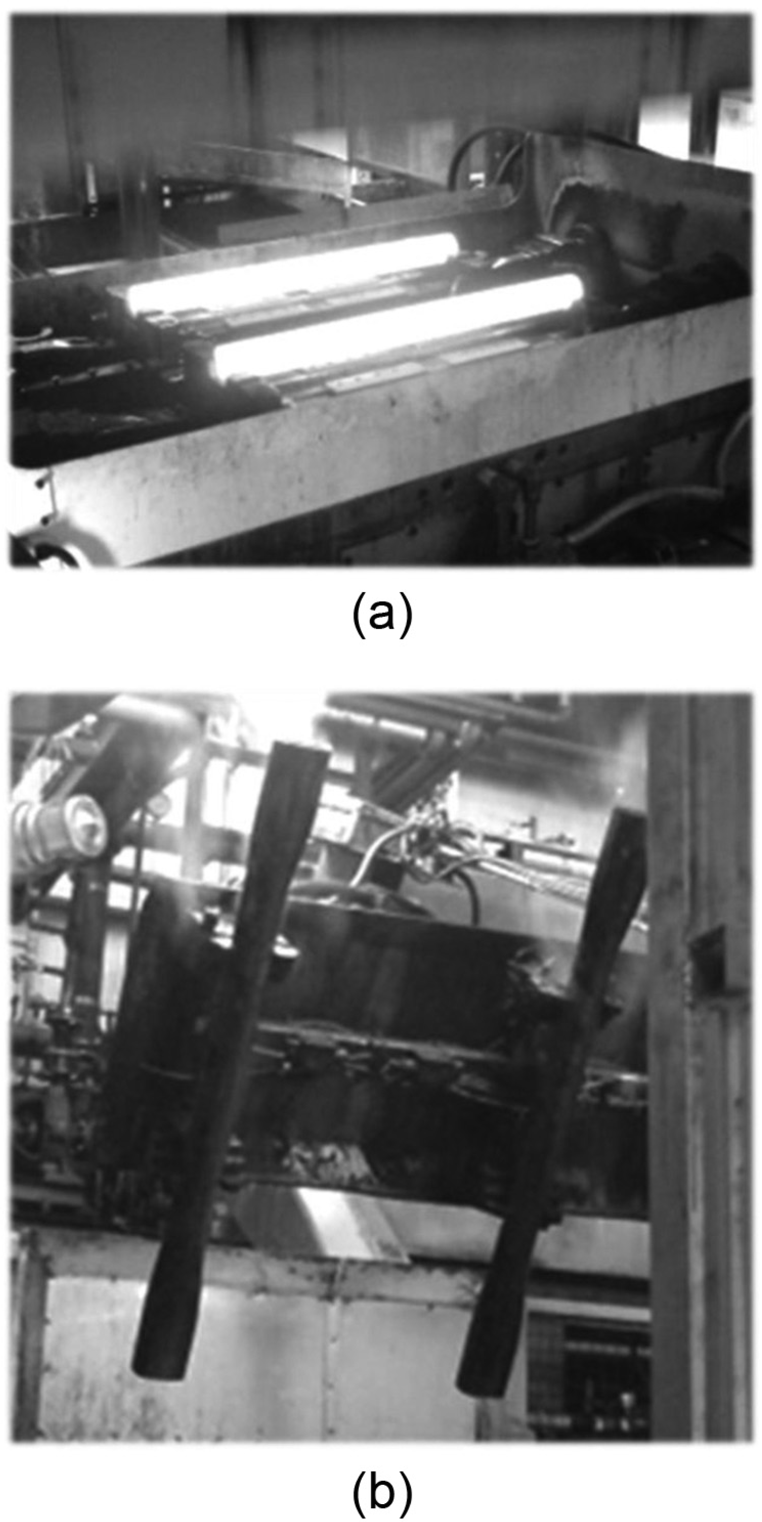
Part shape before and after hot stamping: (a) heated tubes before hot stamping and (b) tubular beams after hot stamping.
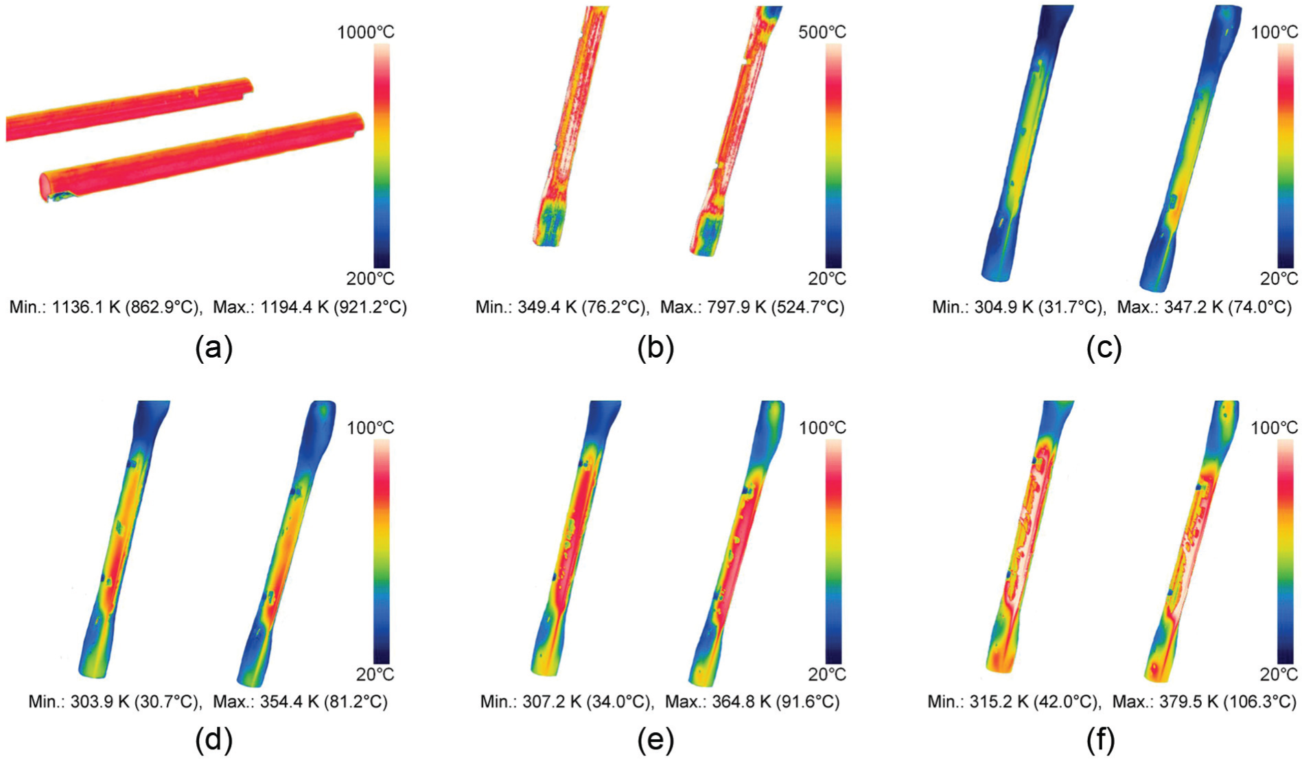
Thermal infrared images for each condition: (a) heated tubes; (b) DQ, cooling time: 22 s; (c) HQ, cooling time: 22 s; (d) HQ, cooling time: 19 s, (e) HQ, cooling time: 16 s, and (e) HQ, cooling time: 13 s.
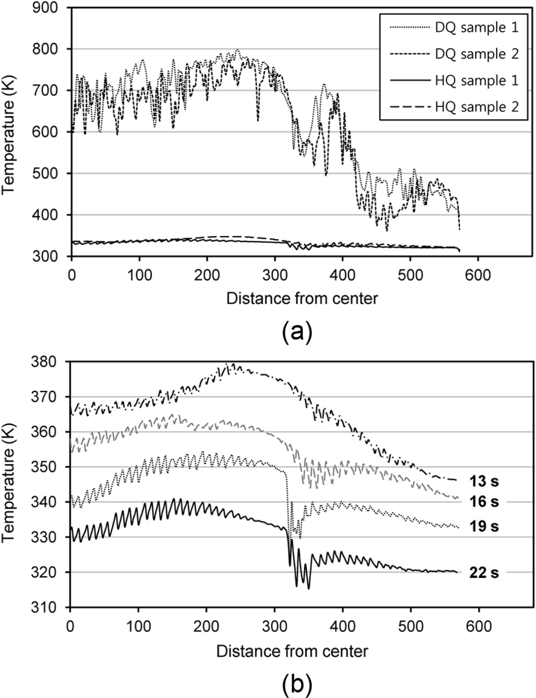
Temperature distribution in upper center of tubular beam for each condition: (a) comparison of temperature distribution between die quenching and hybrid quenching (cooling time: 22 s) and (b) experiment results of temperature distribution with different cooling times.
Figure 10(a) shows the temperature distributions after sustaining 22 s of cooling under die quenching and hybrid quenching. In die quenching, the area located 400–575 mm from the center of the tubular beam, which is contacted by the side core, had a temperature distribution between approximately 400 and 600 K (127 °C and 327 °C). However, in the area with a uniform V-shaped cross section (Figure 2(b), Area III), the temperature distribution was approximately 600–800 K (327 °C–527 °C). Applying cooling times of 22, 19, 16, and 13 s with hybrid quenching as shown in Figure 10(b), it was found that most areas had a temperature distribution under 380 K (107 °C). Specifically, in the area located 300–400 mm from the center of the tubular beam, the temperature dropped rapidly because the inside of the tubular beam was directly quenched by the cooling water sprayed from the side core.
Figure 11 is a comparison between the simulated and experimental results for the maximum temperature depending on the cooling time. In hybrid quenching, the experimental results were similar to that of Case 4 whose WQA and DQA temperatures were 298 and 353 K (25 °C and 80 °C), respectively. Therefore, the simulation condition for Case 4 was considered to be the best for the prediction of the temperature change during hybrid quenching. The simulation conditions proposed in this research are effective and predicted the temperature well.
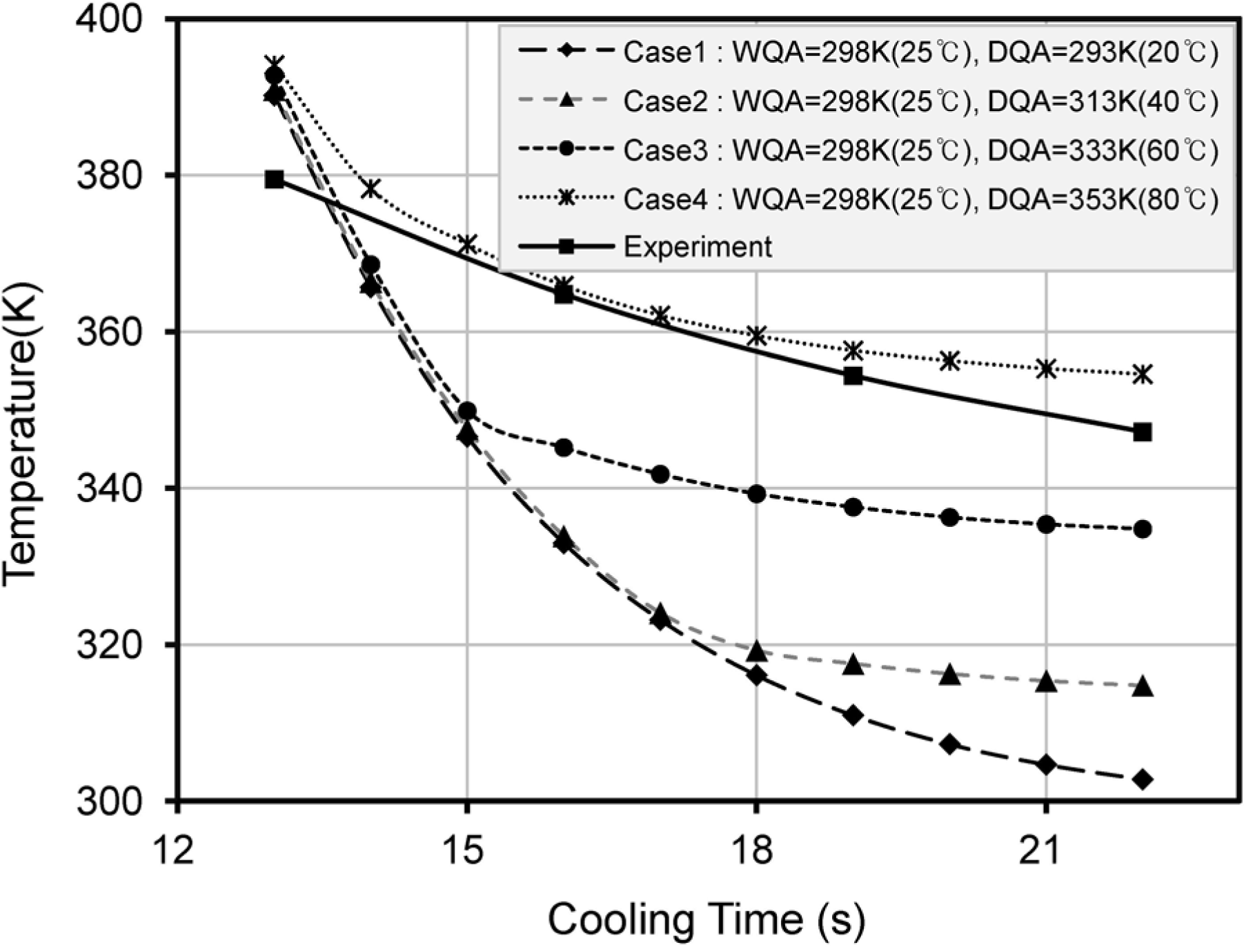
Comparison of simulated maximum temperature of tubular beam for each case with experiments.
Phase transformation
Figure 12 shows the simulation results for the martensite volume fraction for each case after hybrid quenching for 13 s of cooling. For Cases 1–4, there was no significant difference in the martensitic volume fraction; the minimum martensite volume fractions were from 89.6% to 90.7%, indicating that 13 s of cooling is enough for martensite formation in hybrid quenching.
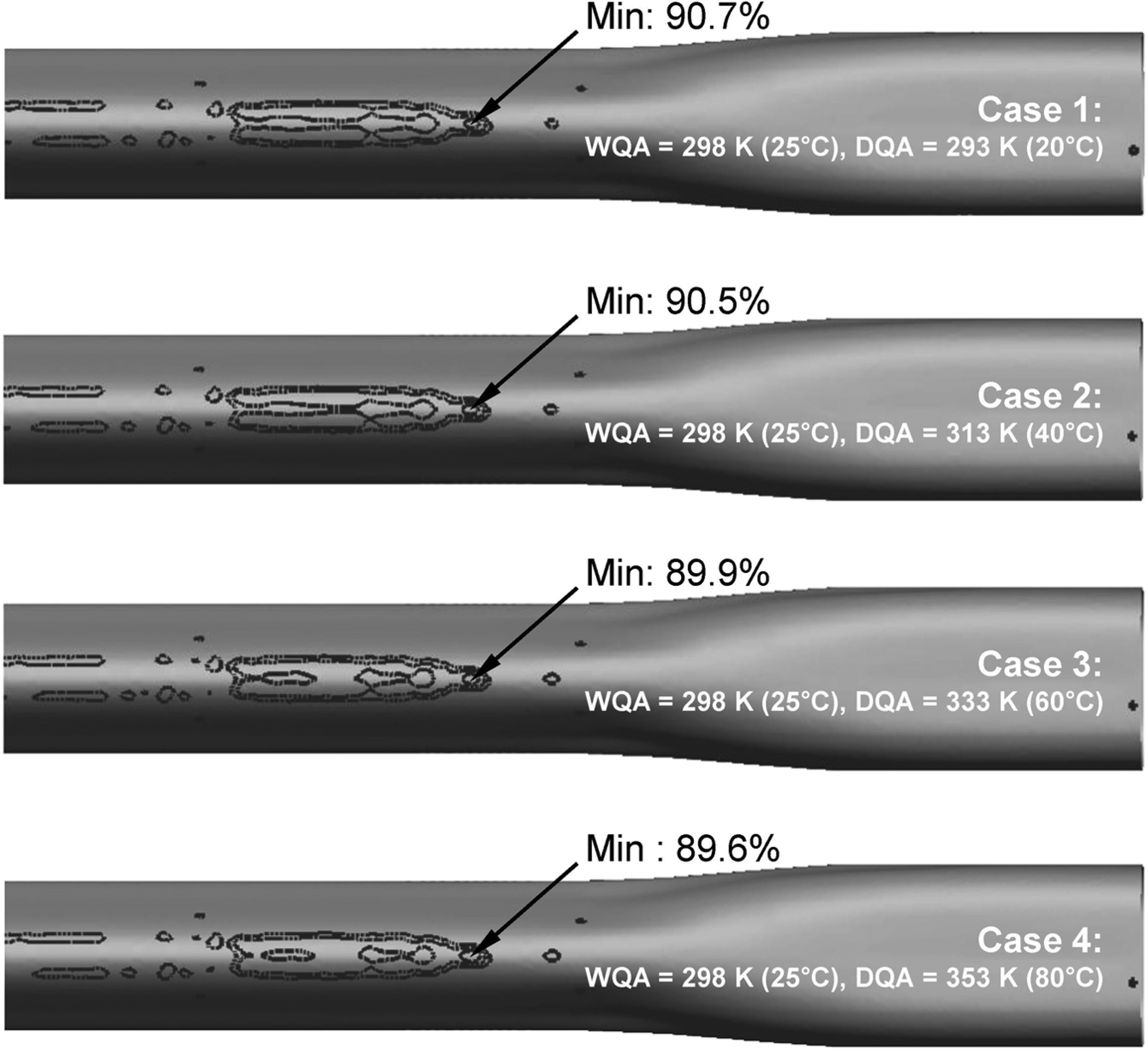
Analysis results for martensite volume fraction for each case.
Figure 13 shows the microstructures of the specimens collected at 200 mm from the center of the tubular beam. In die quenching (cooling for 22 s, Figure 13(a)), multiple phases of bainite and martensite were found. However, in hybrid quenching (cooling for 13 s, Figure 13(b)), most of the microstructure was martensite.
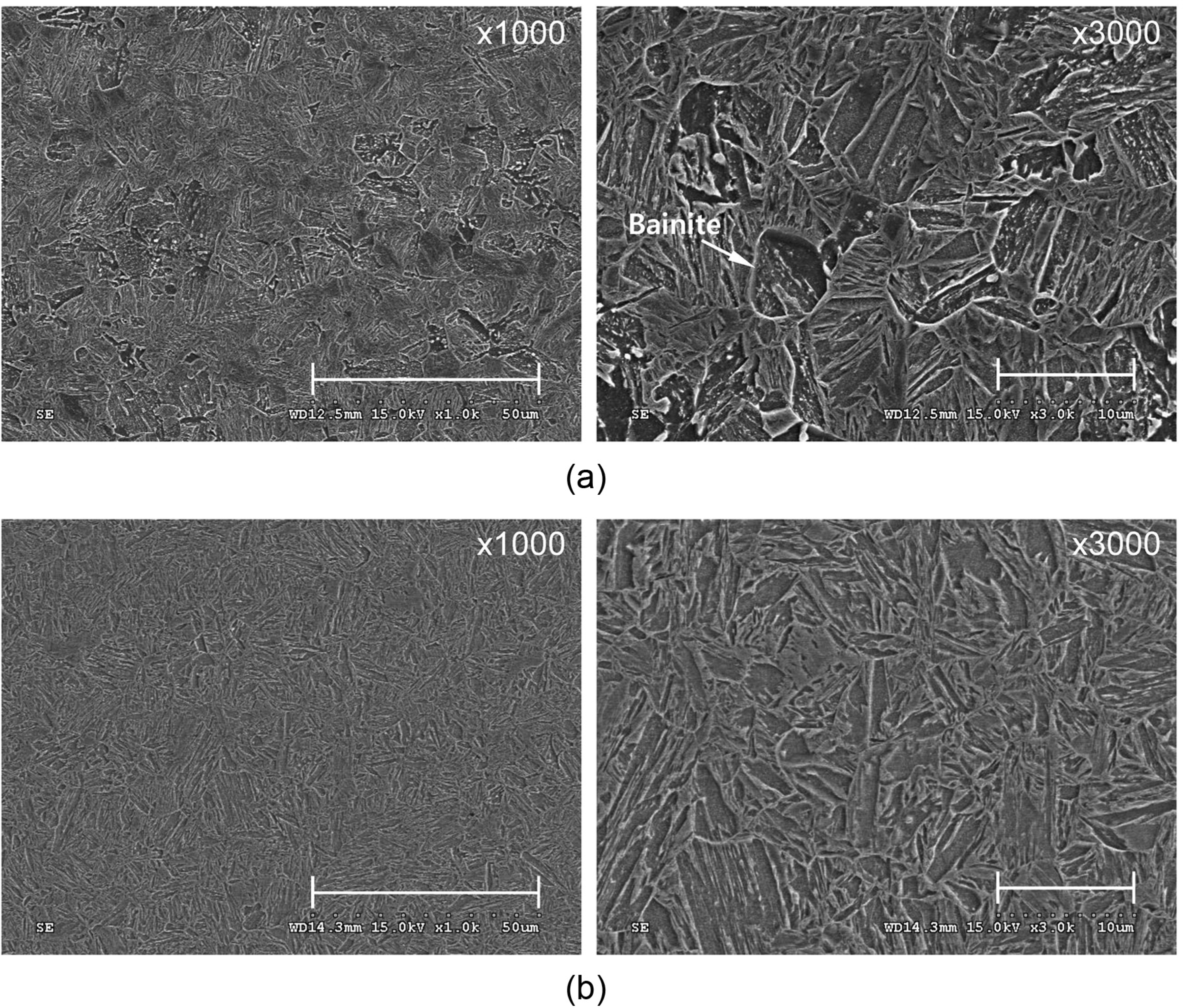
Comparison of microstructures between die and hybrid quenching: (a) die quenching (cooling time: 22 s) and (b) hybrid quenching (cooling time: 13 s).
Mechanical properties (tensile strength and hardness)
In this study, tensile and hardness tests of the tubular beam were carried out to verify the effectiveness of hybrid quenching. For the tensile test, four tensile specimens were taken from the center of the tubular beam where cooling is most likely to be insufficient. The tensile test specimen follows the KS B0801 13B (ISO6892) standard. For the areas where the tensile specimen is hard to be taken, the hardness was measured alternatively. 36 The hardness measurement points were located on each cross-sectional surface at 0, 400, and 500 mm from the center of the tubular beam. The hardness values were measured by Vickers hardness.
The tensile and hardness results for the tubular beam processed by die quenching at 22 s and hybrid quenching at four cooling times from 13 to 22 s at 3 s intervals are shown in Figure 14(a) and (b), respectively. For die quenching, the mechanical property results did not reach the target values (tensile strength of 1400 MPa and hardness of Hv 425) because the cooling rate was not fast enough to get the full martensite in the non-contact areas with the die and in the uniform cross section area (Area III in Figure 2(b)) where the thickness is doubled. However, for hybrid quenching, the tensile strength and hardness exceeded the target values even at a cooling time of 13 s. Therefore, 13 s of cooling is enough to obtain the target values for the mechanical properties, and hybrid quenching is very effective for reducing the process cycle time.
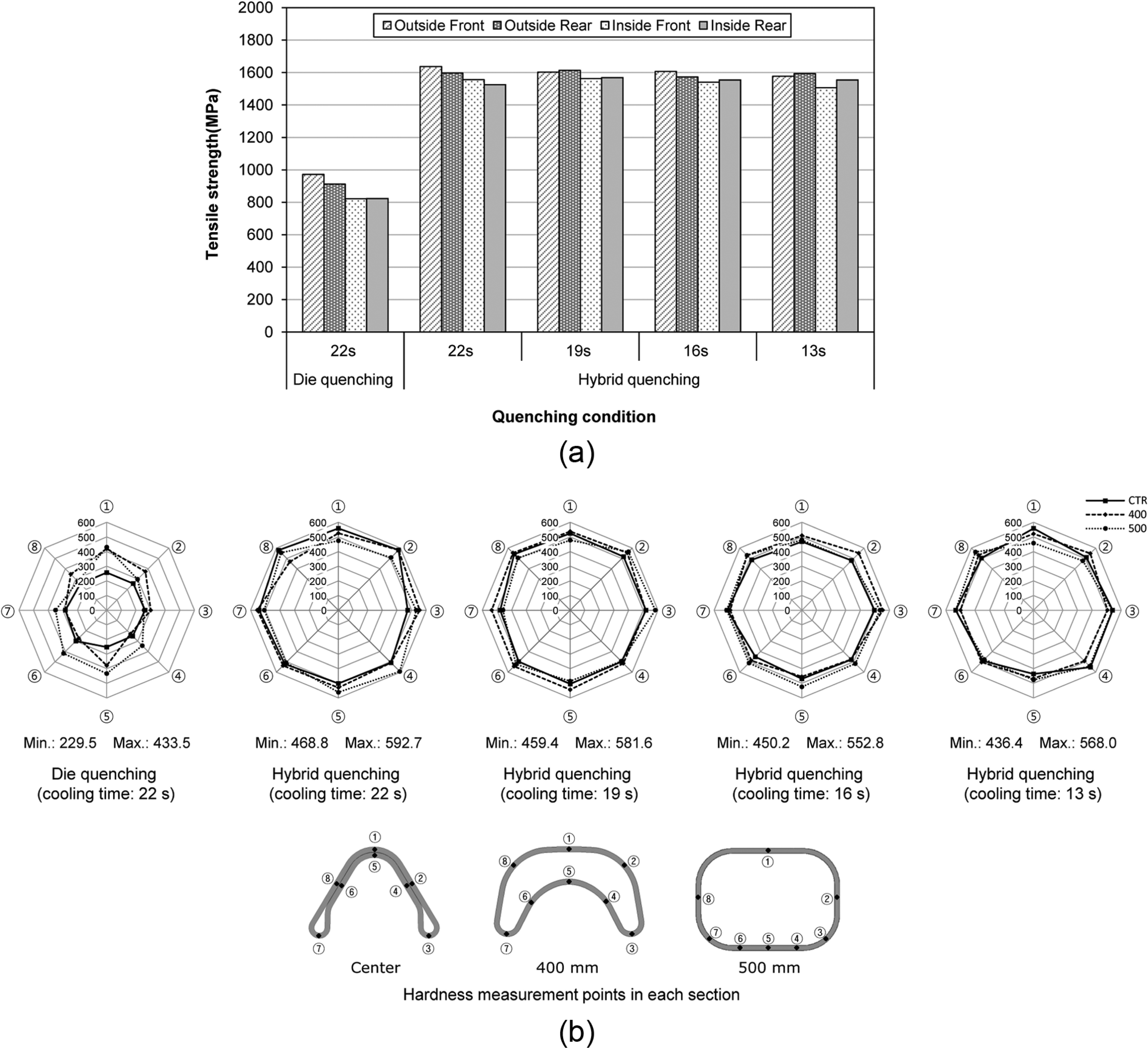
Comparison of mechanical properties between die and hybrid quenching: (a) tensile test results and (b) hardness measurement results (measurement location: 0, 400, and 500 mm).
Thermal deformation
Typically, hot stamping is an effective process to control springback. However, the short cooling time or the insufficient cooling capacity can cause thermal deformation rather than springback. To evaluate the thermal deformation of the tubular beam, the center height was measured with both ends of the beam supported. Four tubular beams for each condition were sampled to reduce the measurement error. In Figure 15, the results of the thermal deformation at each condition are compared.
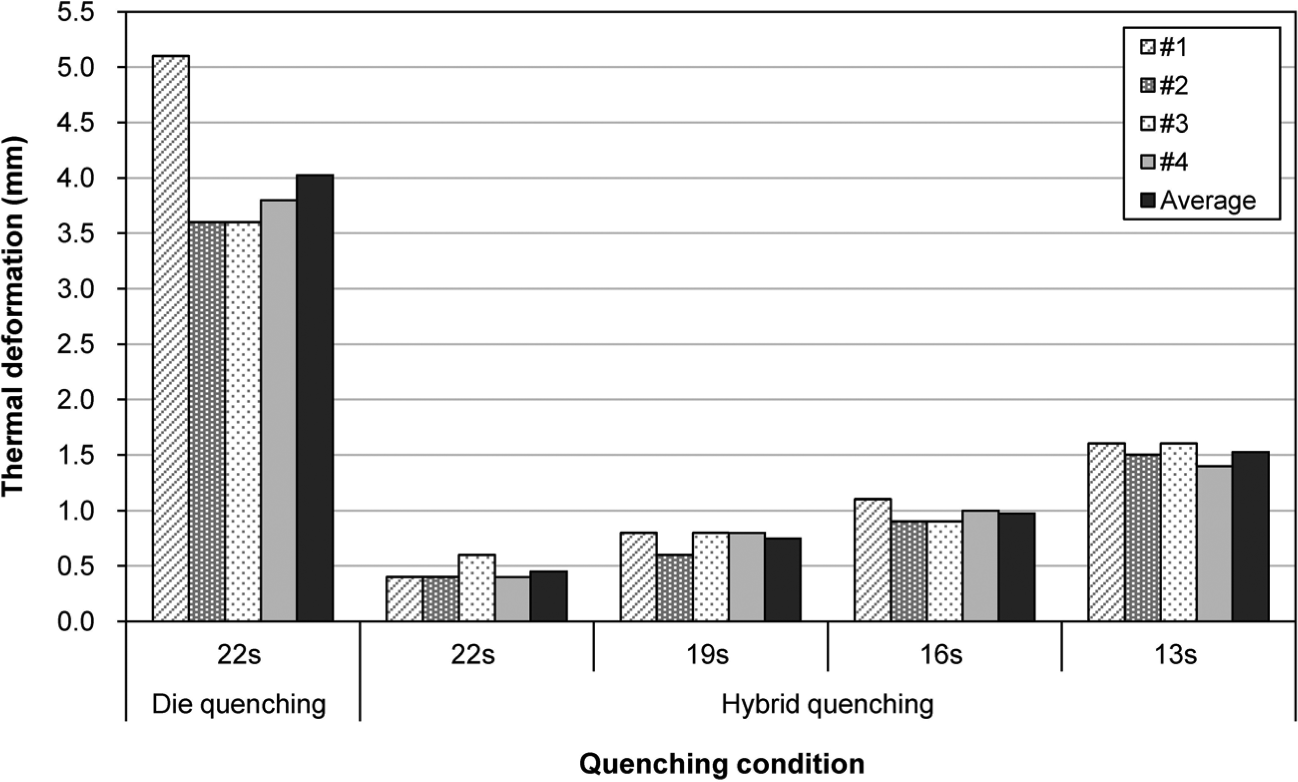
Comparison of thermal deformation between die and hybrid quenching.
In die quenching, the maximum and average thermal deformations were 5.1 and 4.0 mm, respectively. In hybrid quenching, the average thermal deformations for cooling of 22, 19, 16, and 13 s were 0.5, 0.8, 1.0, and 1.5 mm, respectively. These results show that a longer cooling time causes less thermal deformation, but the difference between 0.5 and 1.5 mm is insignificant considering the size of the tubular beam.
The small deformation in hybrid quenching is because uniform cooling occurs on the surface of the tubular beam during hybrid quenching, so thermal expansion and phase transformation are uniform. The small deformation for longer cooling times is because the die is constrained from deformation for a longer time. Uniform cooling and longer die cooling are very effective in reducing deformation during hot stamping.
Conclusion
The rear CTBA as a vehicle component has been developed with tubular-type beam using hot stamping process to enhance the strength and reduce the springback. However, this hot stamping process for the tubular beam has difficulties in cooling the tubular beam. The thickness of the tubular beam from edge to center has variation after forming. The thickness of the tubular beam on the center section is twice compared to the other sections because the upper surface contacts with the lower surface. Furthermore, even if indirect hot stamping with water quenching is applied to obtain the required mechanical properties, control of the thermal deformation is difficult because the product is long.
In this study, hybrid quenching was suggested to solve these problems, and the effectiveness of the suggested method was verified experimentally. To analyze hybrid quenching results, FE simulations were performed with different DQA and WQA temperatures. Suitable temperature conditions for hybrid quenching were obtained by comparing the simulation and experimental results. When the die quenching with cooling of 22 s was applied, the required tensile strength and hardness values could not be achieved for the tubular beam. The possible reasons for the insufficient mechanical properties are a slow cooling rate, the presence of non-contact areas between the die and the tubular beam, and the thickness of the tube. However, under hybrid quenching, even when the cooling was sustained for just 13 s, the measured mechanical properties exceeded the target values. It means that hybrid quenching is very effective for reducing the cooling rate. In addition, in terms of thermal deformation, hybrid quenching was very effective. If the hybrid quenching is applied to hot stamping items, it will improve the product quality and shorten the process cycle time.
Footnotes
Declaration of conflicting interests
The author(s) declared no potential conflicts of interest with respect to the research, authorship, and/or publication of this article.
Funding
This work was supported through the National Research Foundation of Korea (NRF) grant funded by the Korea Government (2014R1A2A2A01005903) and also Kyungpook National University Research Fund (2013).