
Abstract
This article presents a derivation of the stiffness matrix of a general redundantly actuated parallel mechanism based on the overall Jacobian. The Jacobian of the constraints and actuations is derived using reciprocal screw theory. Based on the mapping relationship between constraint, actuated and external forces combined with the principle of virtual work, a compatibility equation for the deformation of all of the limbs is achieved, and the stiffness model of the general redundantly actuated parallel mechanism is derived. The 5-UPS/PRPU redundantly actuated parallel machine tool is used to illustrate this method. The parallel machine tool comprehensively reveals the effect of the elastic deformation of active–passive joints and some basic transmission parts. The stiffness model is further validated by experimental data. Moreover, the global stiffness matrix of the general redundantly actuated parallel mechanism can be separated into two parts via matrix decomposition. The first part is the stiffness matrix of the corresponding non-redundant parallel mechanism, and the second part is the stiffness matrix of the redundantly actuated limbs (actuators). The redundantly actuated 5-UPS/PRPU parallel machine tool is also investigated for further analysis. The different stiffness characteristics of the machine tool and its corresponding non-redundant 5-UPS/PRPU parallel machine tool are compared. Actuation redundancy is found to improve the stiffness performance of the machine tool efficiently.
Introduction
In recent years, redundantly actuated parallel mechanisms have been investigated and developed out of the belief that they have many benefits compared with their non-redundant counterparts. These benefits include the following:
As one of the most important performance characteristics of parallel mechanisms, stiffness can be understood as the capacity of a mechanical system to maintain loads without any excessive change to the intrinsic geometry of the system. For high-precision mechanical systems such as machine tools 6 , a stiffer structure indicates higher accuracy and higher machining speeds in the end effector. Therefore, determining the stiffness model matrix and investigating its stiffness characteristics over its workspace are necessary and can help programmers direct tool motion planning. Some studies7–16 have examined the modelling methods and stiffness characteristics of parallel mechanisms. Bi 10 applied the kinetostatic method to develop a stiffness model. Wang et al. 11 analysed the stiffness characteristics of a Tricept robot while considering the bend deformation of the constrained passive limb. Joshi and Tsai 17 compared the stiffness characteristics of a Tricept robot with a 3-UPU manipulator while considering the bend deformation of the actuator Shin et al. 18 introduced a stiffness enhancement method by additional support rims. However, fewer efforts have been made to examine the stiffness of general redundantly actuated mechanisms while considering compliance in both actuators and links, and few studies have compared the stiffness performance of redundantly actuated parallel mechanisms with that of their non-redundant counterparts. Wu et al. 19 investigated the stiffness performance of a 3-degree of freedom (DOF) parallel manipulator while considering additional supporting limbs. Zhao et al. 5 investigated an 8-PSS parallel manipulator that added two extra limbs to the 6-PSS parallel manipulator.
Although some studies have compared redundant parallel manipulators with their non-redundant counterparts, the objects of research remain redundant parallel manipulators with one or more additional limbs. Few studies have compared the stiffness characteristics of redundant parallel manipulators with those of their non-redundant counterparts while replacing passive joints with active joints.
This article is structured as follows. In the ‘Stiffness matrix of a general redundantly actuated parallel mechanism’ section, the stiffness matrix of a general redundantly actuated mechanism is derived. In the ‘Stiffness evaluation of a 5-UPS/PRPU PMT’ section, the 5-UPS/PRPU redundantly actuated parallel machine tool (PMT) is used to illustrate the modelling method, the accuracy of which is verified via experiments. In the ‘Stiffness analysis of a 5-UPS/PRPU PMT’ section, the stiffness characteristics of the 5-UPS/PRPU redundantly actuated PMT are compared with those of its non-redundant counterpart, the 5-UPS/PRPU PMT. The notations of R, U, S and P denote revolute, universal, spherical and prismatic joints, respectively.
Stiffness matrix of a general redundantly actuated parallel mechanism
Description
A general n-DOF parallel mechanism is called a general n-DOF redundantly actuated parallel mechanism when the number of the active joints is m and m > n. In Figure 1,
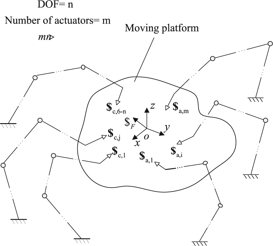
A general redundantly actuated parallel mechanism.
Jacobian analysis
In Figure 1, the reference coordinate system o-xyz is fixed at the centre o of the MP, and all of the following actuation/constraint wrenches are expressed in the frame o-xyz. The external wrench applied on the MP is denoted as
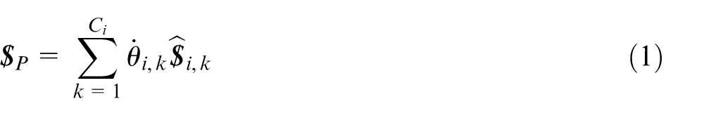
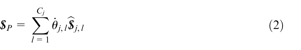
Here, the actuated/constraint limb is considered as a serial chain. The MP is connected to the fixed base by Ci
/Cj
number of 1-DOF joints.
Based on reciprocal screw theory, the screws that are reciprocal to all of the twists of the jth constraint wrench can form a (6 − Cj
) reciprocal screw set. Let
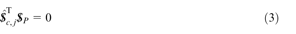
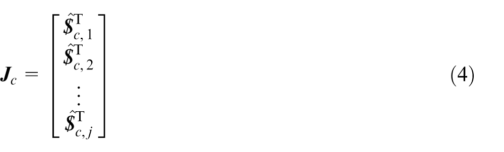
Thus, according to the definition of the Jacobian of constraints, 9 the Jacobian of constraints of the general redundantly actuated parallel mechanism can be obtained by assembling each product
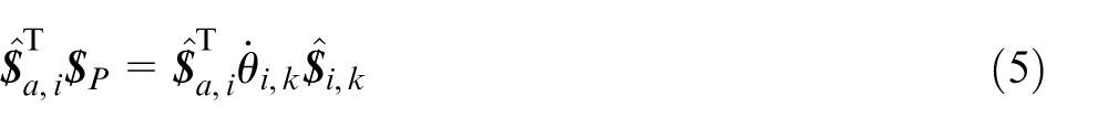
By locking the active joint of each limb, the screws that are reciprocal to all of the unit screws of the twists, apart from the screws of the actuated joints, that is, the actuation wrenches, form an m reciprocal screw set. Given the orthogonal product of both sides of equation (1), the following equation can be obtained
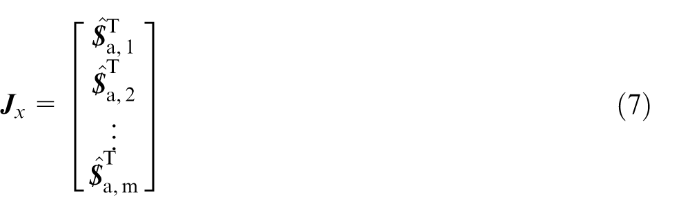
By assembling the m reciprocal screws, the following equation can be obtained

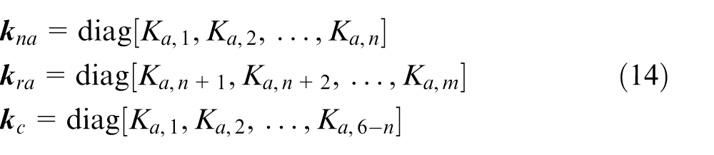
where the matrix
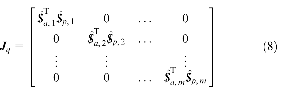

where

where

The Jacobian of non-redundant actuations
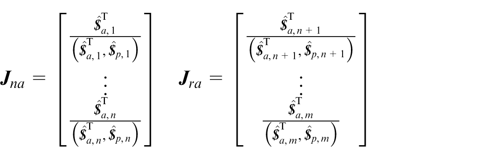
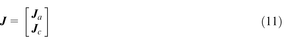
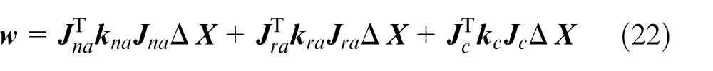
Combining equation (4) with equation (10), we obtain the overall Jacobian of the redundantly actuated parallel mechanism
Stiffness matrix
In this section, the stiffness matrix of the general redundantly actuated parallel mechanism is obtained using the previously derived Jacobian matrix. The axial deformation of the supporting limbs is considered to determine the actual elastic displacement of the MP. In addition, the fixed base and MP are significantly stiffer mechanical structures and are thus assumed rigid, and the coupling deformation is neglected.
Determination of deformation compatibility equation
It is assumed that the external wrench applied on the MP can be expressed as
The reaction forces/moments can be represented as
where
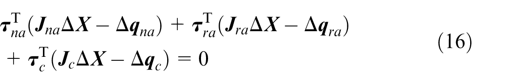
Moreover, let

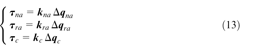
Substituting equations (12) and (13) into equation (15) yields
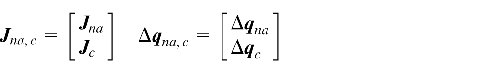
Based on equation (16), the following equations can be obtained


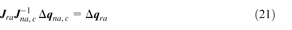
Combining equations (17) and (19) into one equation yields

where
Based on the assumption made at the beginning of this section, each row of
Determination of stiffness matrix
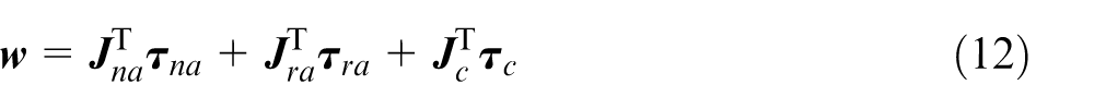
Substituting equations (13) and (17)–(19) into equation (12) yields
where
Via linear transformation, the stiffness matrix
where
There are three types of redundancy. The first is in-branch redundancy, which replaces some of the normally passive joints with the active joints of a parallel manipulator. The second type is actuation redundancy, in which the manipulators are actuated via additional actuated branches that go beyond the minimum necessary. The third type is a hybrid of the first two types. The three types of redundancy are continually modified by corresponding non-redundant mechanisms. Therefore, comparing the stiffness matrix of the redundant mechanism with its corresponding non-redundant mechanism is important when investigating the improvements that result from actuation redundancy. In the next section, a 5-UPS/PRPU redundantly actuated PMT is used as an example and compared with its corresponding non-redundant counterpart.
Stiffness evaluation of a 5-UPS/PRPU PMT
Description
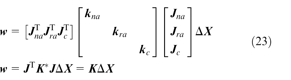
As shown in Figure 2(a), the 5-UPS/PRPU PMT can perform two rotational DOFs and three translational DOFs. The MP and fixed base are connected by five UPS limbs and a PRPU limb. The five UPS limbs are driving limbs that are able to change their length to transform the pose of the MP. The PRPU limb is a passive limb that constrains the rotational DOF of the MP around its normal axis.
Virtual prototypes of a 5-UPS/PRPU redundant PMT and its non-redundant counterpart. (a) Virtual prototype of the 5-UPS/PRPU PMT: 1. P Joint, 2. R Joint, 3. P Joint, 4. U Joint, 5. S Joint, 6. Spindle, 7. MP, 8. U Joint, 9. Fixed base and 10. Motor. (b) Virtual prototype of the 5-UPS/PRPU redundant PMT.
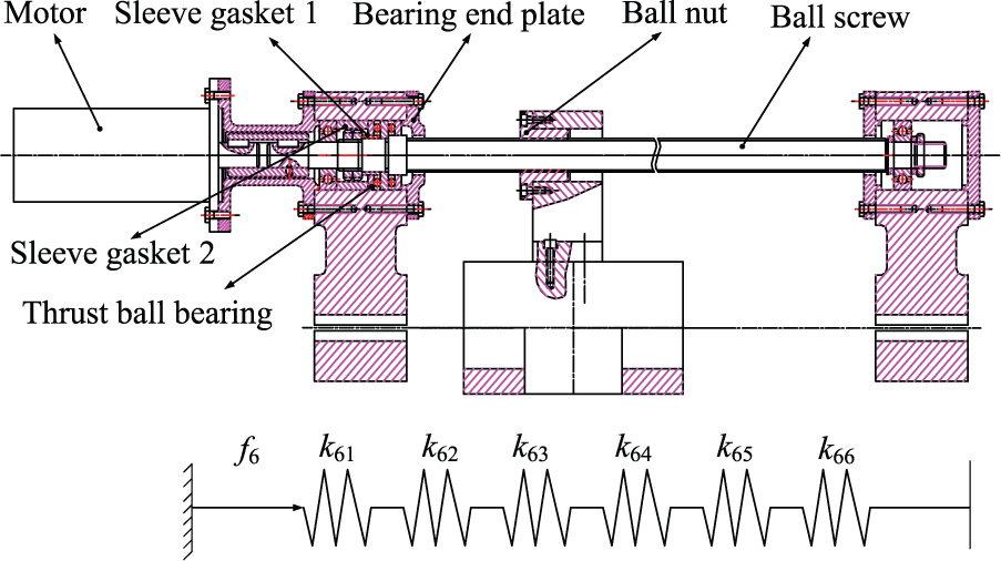
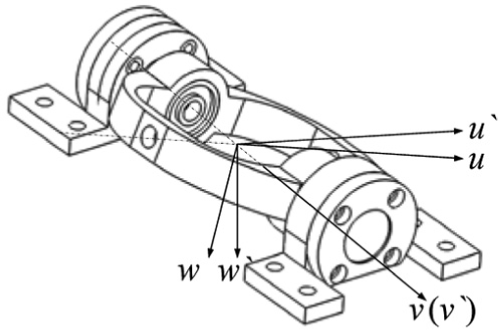
The outstanding feature of the PMT is that the expression of the forward/inverse dynamic solutions of the constraint limb (PRPU limb) is very concise. Each joint variable of the PRPU limb can be measured by installing sensors on the joint connection, which can be used to calculate the pose of the MP in real time via a direct analytical formula expression of the joint variables. To avoid singularity, improve dynamic performance and realise the closed-loop control of the PMT, a redundant actuator is installed on the PRPU limb (Figure 2(b)). Thus, the PMT can be described as a 5-UPS/PRPU redundantly actuated PMT and a 5-UPS/PRPU non-redundant actuated PMT. Figure 3 shows the improved structure of the 5-DOF redundant PMT and PRPU limb.
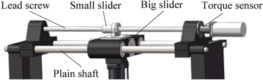
Virtual prototype of the redundantly actuated joint.
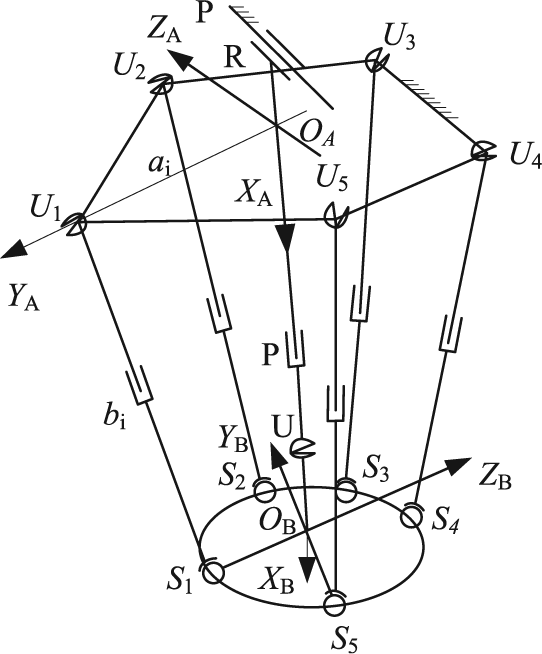
Figure 4 presents a schematic diagram of the 5-UPS/PRPU PMT. A base Cartesian coordinate frame designated as the OA-XAYAZA frame is fixed at the centre of the fixed base with the x-axis pointing vertically downwards and the y-axis pointing at the universal joint U 1. A coordinate frame OB-XBYBZB is similarly assigned to the centre of the MP, with the x-axis normal to the platform and the z-axis pointing in the opposite direction to the spherical joint S 1. Following analysis is based on this coordinate system.
Schematic diagram of the redundant PMT.
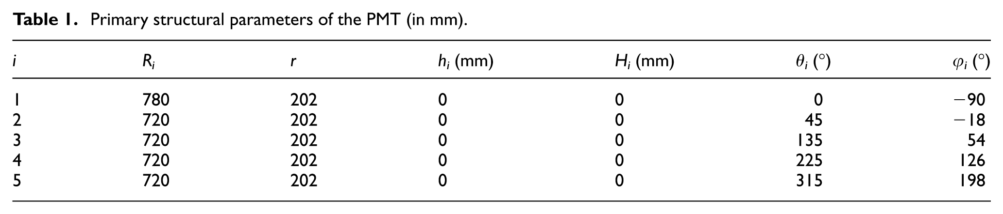
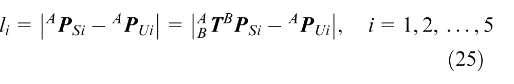
Ui (i = 1, 2, red) is the centre of the universal joint distributed on the fixed base (on a circle with a radius of 720 mm). Si (i = 1, 2, us) is the centre of the spherical joint distributed on the MP (on a circle with a radius r of 200 mm). S 1 is located on the ZB -axis. The position coordinate of the universal joint Ui in frame {A} can be expressed as
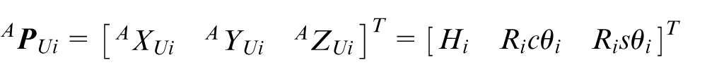
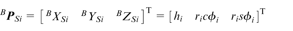
where Ri denotes the distance from OA to Ui, θi denotes the angle between YA and Ri and Hi denotes the x coordinate of Ui in the base coordinate system {A}. The position coordinate of the universal joint Bi in frame {B} can be expressed as
where Ri
denotes the distance from OA
to Ui
,
Primary structural parameters of the PMT (in mm).
If
where
Jacobian matrix derivation
The twist of the MP can be defined as
where
For the purpose of analysing the kinematic characteristics of the 5-UPS/PRPU PMT, the screw system of the PRPU limb is established and shown in Figure 5.
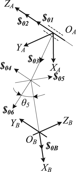
Kinematic screw of the PRPU limb.
In Figure 5,
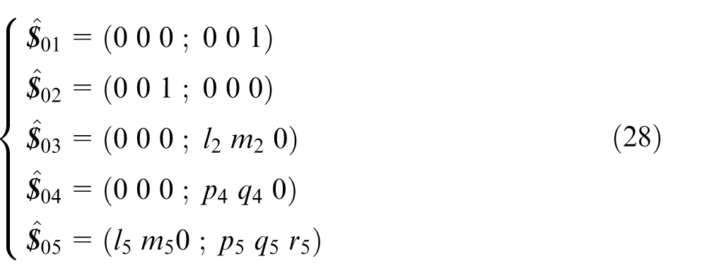
According to reciprocal screw theory, 20 the structure restraint screw of the PRPU limb can be expressed as

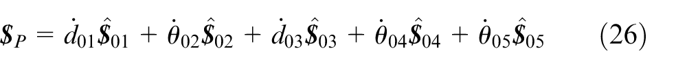
Equation (29) shows that the motion around the normal axis of the MP is constrained. Given the reciprocal product of both sides of equations (26) and (29), the following can be obtained

where
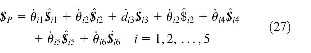
Moreover, by locking the actuators of each UPS limb, the new constraint forces reciprocal to all of the passive joints can be expressed as
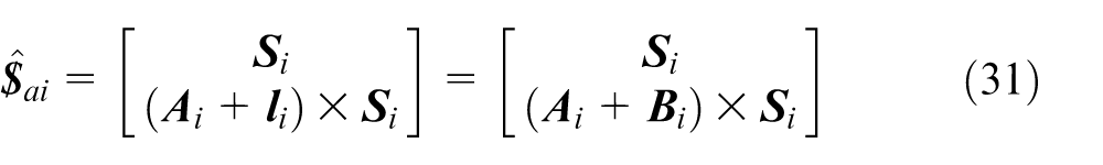
which points along the axial direction of each limb. In equation (31),
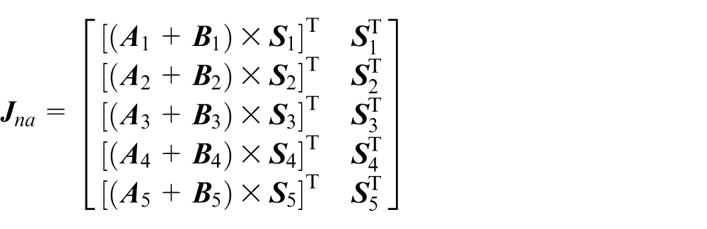
In the same way, taking the reciprocal product of both sides of equations (27) and (31), the following equations can be derived in matrix form

where
Likewise, by locking the first prismatic joint of the PRPU limb, the constraint force exerted on the universal joint, which is parallel to the axis of the first prismatic joint, can be obtained
where
Stiffness modelling
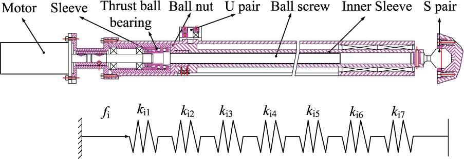
In this section, the stiffness models of each driving limb of the 5-UPS/PRPU PMT are investigated based on the following assumptions. First, according to the mechanical behaviour of each driving limb, the UPS limbs and parts of the PRPU limb are equivalent to two-force bars. Therefore, only the deformation along its axis direction is considered. Second, the MP, fixed base and small/big slider are significantly stiffer mechanical structures and are thus assumed rigid. As the swing bar (RPU6 in Figure 5) is not subjected to tension and compression, its axial stiffness is neglected. Third, as shown in Figures 6 and 7, analysis of the actual structure of each limb reveals that the stiffness of each limb is equivalent to a series spring.
Structure of UPS limb.
Partial structure of the PRPU limb.
The linear stiffness of the UPS limb can be expressed as
where
The linear stiffness of the first prismatic joint of the PRPU limb can be expressed as
where
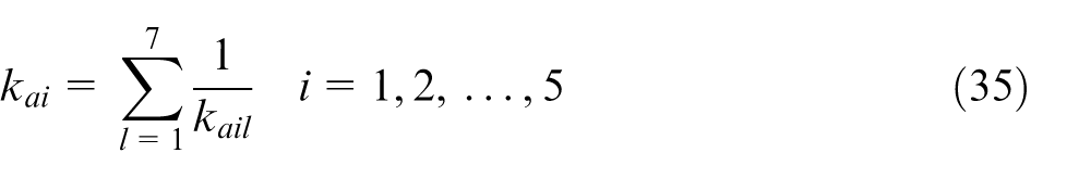
Stiffness of the active joint
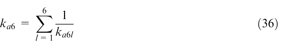
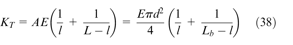
The axial stiffness of the general ball screw is correlated with its installation method. There are three methods: one end anti-thrust with the other end free, one end anti-thrust with the other end hinged and both ends anti-thrust. For the first two methods, the axial stiffness can be expressed as
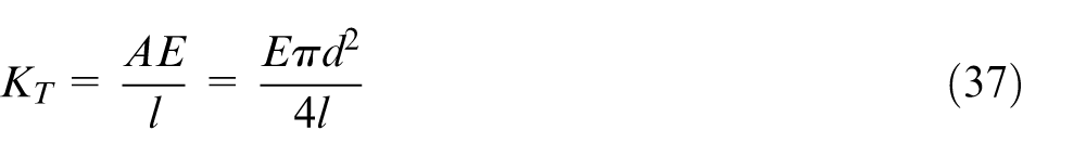
where A is the minimum cross-sectional area of the ball screw, E is the modulus of elasticity, l is the distance between the load acting point and support.
For the third method, the axial stiffness can be expressed as
Stiffness of passive joint
According to the mechanical behaviour of the UPS limb, the linear stiffness of the U joint along the axis direction of each limb should be considered.
Structure diagram of U joint.
Let
Stiffness of the ball bearing
According to Hertz contact theory, the relationship between the contact load and elastic approach of the two contact bodies can be expressed as
where
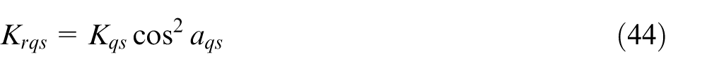
With the contact angle and load of the ball and bearing raceway as the known quantity, the contact stiffness of each ball and bearing raceway can be expressed as
where the subscripts q, e and s represent inner race, outer race and the sth ball, respectively (Figure 9).
Contact stiffness between balls and raceways.
The radial and axial stiffness component of the inner/outer race can be expressed as


where
Based on the series and parallel connection relationships between the stiffness of the Z balls in a ball bearing, the axial stiffness
Here, the contact angle is 15° and the pre-tightening force is 60 N according to the manufacturer recommendation.
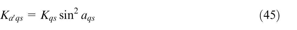
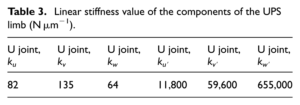
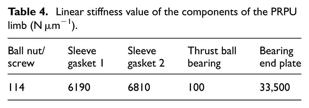
Stiffness value of the components
The specific stiffness value of the related components can be achieved via finite element method (FEM) simulation or experimental test (see Tables 2–4). The derivation process is not discussed here.
Linear stiffness value of the components of the UPS limb (N µm−1).
Linear stiffness value of the components of the UPS limb (N µm−1).
Linear stiffness value of the components of the PRPU limb (N µm−1).
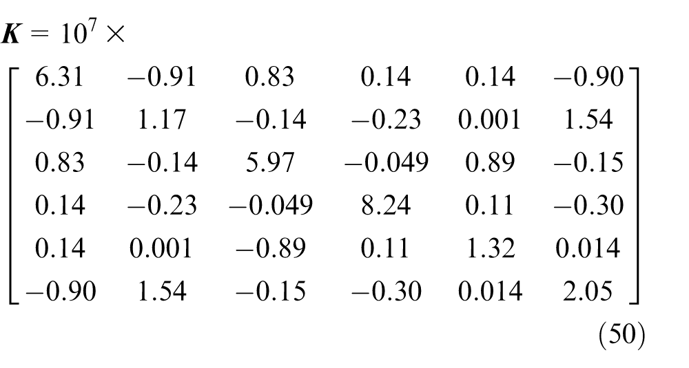
Stiffness matrix description
The stiffness matrix of the 5-UPS/PRPU PMT can be obtained by substituting all of the parameters into equation (23). It can be decomposed into the following form

For the redundantly actuated PMT,
Experimental verification
Figure 10 shows the initial configuration of the PMT. The coordinates of the central point of the MP in this position is
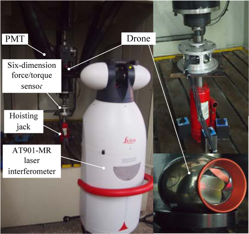
Stiffness measurement experiment of the PMT.
A hoisting jack is used as an output load to verify the accuracy of the stiffness model. The acting force imposed on the MP can be detected by a six-dimension force/torque sensor, and the micro-displacement of the MP can be measured via AT901-MR laser interferometer. In addition, according to
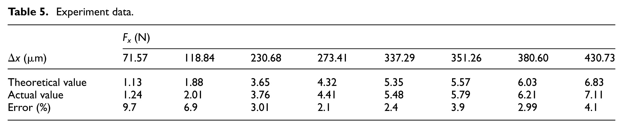
To avoid the influence of the deformation caused by gravity, the initial coordinate of the MP is measured without a hoisting jack. Thus, when the hoisting jack imposes a load on the MP, the micro-displacement can be obtained by subtracting the two measured values. Moreover, as the laser interferometer is very sensitive to external disturbance (e.g. noise and vibration), the relative standard deviation of 10 measurements is calculated to guarantee the accuracy of the experiment, which is shown in Table 5.
Table 5 compares the theoretical and actual values of the micro-displacement under different loads. The micro-displacement under a larger load exhibits a more significant difference. When the load is increased to 200 N or higher, the error range is 2%−5%, which is accepted when man-made measurement errors and outside environmental factors are considered. The other five micro-displacements can be obtained in the same way. However, due to space limitations, the experimental process is not discussed here.
Experiment data.
Stiffness analysis of a 5-UPS/PRPU PMT
To investigate the influence of actuation redundancy on the stiffness performance of the PMT, the stiffness distribution of the redundantly actuated 5-UPS/PRPU PMT and its non-redundantly actuated counterpart are compared as shown in Figure 11. Equation (20) notes that entries of the stiffness matrix consist of information about the structural attributes and configuration of the PMT. Therefore, it is of the utmost importance to study the stiffness distribution of the 5-DOF PMT in correspondence with different positions and orientations. The minimum and maximum linear/angle stiffness are calculated and compared under different swing angles (α and β) as follows.
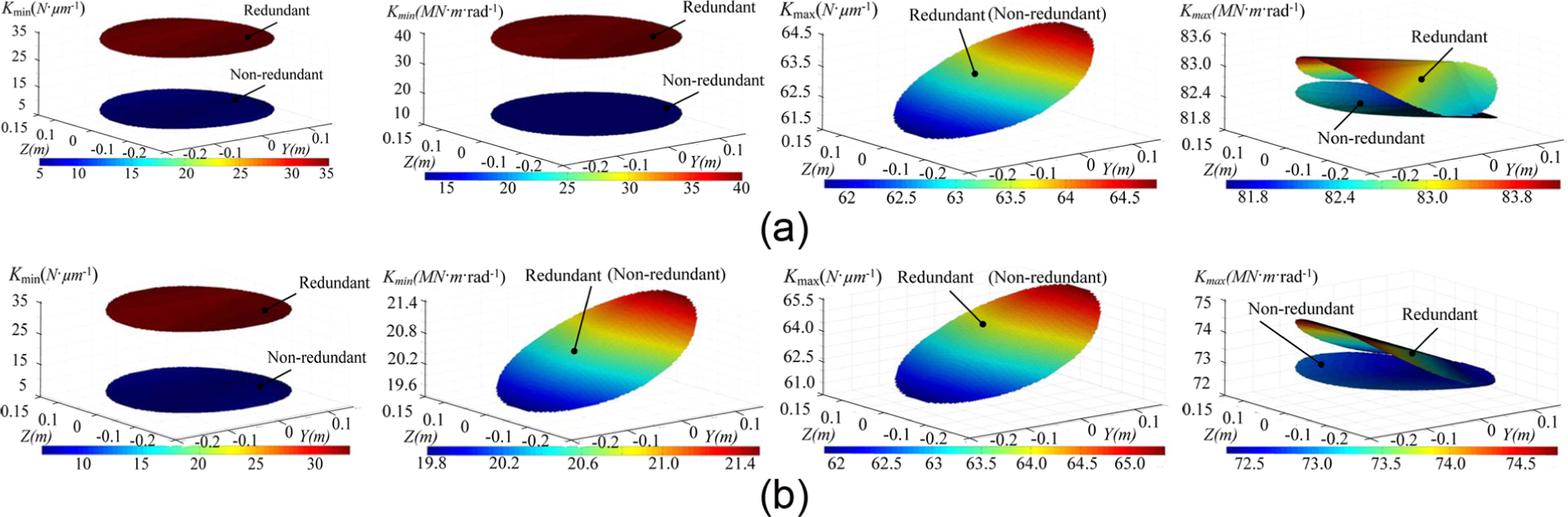
Stiffness distribution of the redundantly actuated PMT and its corresponding non-redundantly actuated PMT in a plane of x = 1.1 m. (a) Minimum/maximum linear/angular stiffness of the PMT corresponding to the attitude angle α = 0°, β = 0°: (a-1) minimum linear stiffness, (a-2) minimum angular stiffness, (a-3) maximum linear stiffness and (a-4) maximum angular stiffness. (b) Minimum/maximum linear/angular stiffness of the PMT corresponding to the attitude angle α = 10°, β = 0°: (b-1) minimum linear stiffness, (b-2) minimum angular stiffness, (b-3) maximum linear stiffness and (b-4) maximum angular stiffness.
Comparison indicates that the minimum of the linear/angle stiffness are symmetric to the y-axis, which complements the symmetric architecture of the PMT. Moreover, the minimum value of the linear/angle stiffness is distributed on the edge of the workspace, the area in which singularity always appears. In addition, the linear/angle stiffness tends to be the nearby minimum value (z = 0 m, y = −0.13 m). The programmer should try to avoid this area when planning the trajectory of the PMT.
Both linear and angle stiffness are symmetric about the y-axis. Figure 11(a) and (b) compares the influence of actuation redundancy on the stiffness distribution of the 5-UPS/PRPU PMT. In Figure 11(a-1) and (a-2), the minimum stiffness of the redundant PMT is higher than that of the non-redundant PMT. However, actuation redundancy has almost no influence on the maximum stiffness of the PMT when α = 0° and β = 0°. When the angle α is changed, the minimum angular stiffness is not affected by actuation redundancy. Thus, to investigate the relationship between the different attitude angle and the corresponding stiffness distribution of the PMT, the isotropic values of the linear/angular stiffness are calculated as a stiffness performance index that corresponds to different swing angles.
Figure 12(a)–(d) shows that although the variation of attitude angle α can affect the stiffness performance of the PMT, the attitude angle β cannot. In addition, the swing angle β does not affect the isotropy index of the linear stiffness
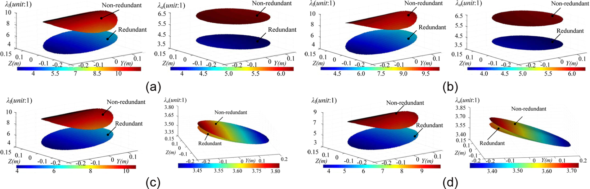
Isotropy index distribution of the redundantly actuated PMT and its corresponding non-redundantly actuated PMT in a plane of x = 1.1 m. (a) Linear/angle stiffness isotropy index distribution corresponding to the attitude angle α = 0°, β = 0° (where
Conclusion
The following four conclusions can be drawn:
The stiffness matrix of a general redundantly actuated parallel mechanism is derived based on the Jacobian of actuations and constraints. The stiffness modelling method is validated via a test of the stiffness performance of the 5-UPS/PRPU PMT.
The global stiffness matrix can be separated into two parts: the stiffness matrices of the corresponding non-redundant parallel mechanism and redundant actuators (or limbs). This is significant when comparing the stiffness performance of the redundantly actuated mechanism with that of its corresponding non-redundant mechanism, which can be used to study the influence of actuation redundancy.
The 5-UPS/PRPU redundantly actuated PMT and 5-UPS/PRPU non-redundantly actuated PMT are used to illustrate the influence of actuation redundancy. The redundant actuator can improve the stiffness isotropy of the PMT, which indicates that the load-carrying capacity of the PMT along each direction can be improved.
In addition, this modelling method reveals the stiffness behaviour of the PMT, providing a theoretical reference for the programmer to plan the trajectory. Furthermore, the modelling method is valuable in predicting the stiffness performance of a mechanism over its workspace, assessing whether the stiffness requirement can be satisfied and achieving an optimal design during the design stage. The stiffness modelling method presented in this study is very important for stiffness performance evaluation, static analysis and mechanism design.
Footnotes
Appendix 1
Declaration of conflicting interests
The author(s) declared no potential conflicts of interest with respect to the research, authorship and/or publication of this article.
Funding
The author(s) disclosed receipt of the following financial support for the research, authorship, and/or publication of this article: This research is financially supported by the National Natural Science Foundation of China (Grant No. 51275439).