
Abstract
Investment casting process is known to its capability of producing clear net shape, high-dimensional accuracy and intricate design. Consistent research effort has been made by various researchers with an objective to explore the world of investment casting. Literature review revealed the effect of processing parameters on output parameters of cast specimen. This article highlights the advancements made and proposed at each step of investment casting and its hybridization with other process. Besides, investment casting has always been known to manufacture parts such as weapons, jewellery item, idols and statues of god and goddess since 3000 BC; this article reviews the present applications and trends in combination of rapid prototyping technique as integrated investment casting to serve in medical science. Advancements in shell moulding with incorporation of fibre and polymer, development of alternative feedstock filament to fused deposition modelling are duly discussed. The aim of this review article is to present state of art review of investment casting since 3200 BC. This article is organized as follows: in section ‘Introduction’, introduction to investment casting steps is given along with researches undertaken at each step; in section ‘Rapid prototyping technique’, background is given on the concept of rapid prototyping technique by examining the various approaches taken in the literature for defining rapid prototyping technique; section ‘Biomedical applications of RPT’ presents the medicine or biomedical applications of investment casting and rapid prototyping technique; section ‘Future trends’ provides some perspectives on future research and section ‘Conclusion’ closes the article by offering conclusions.
Introduction
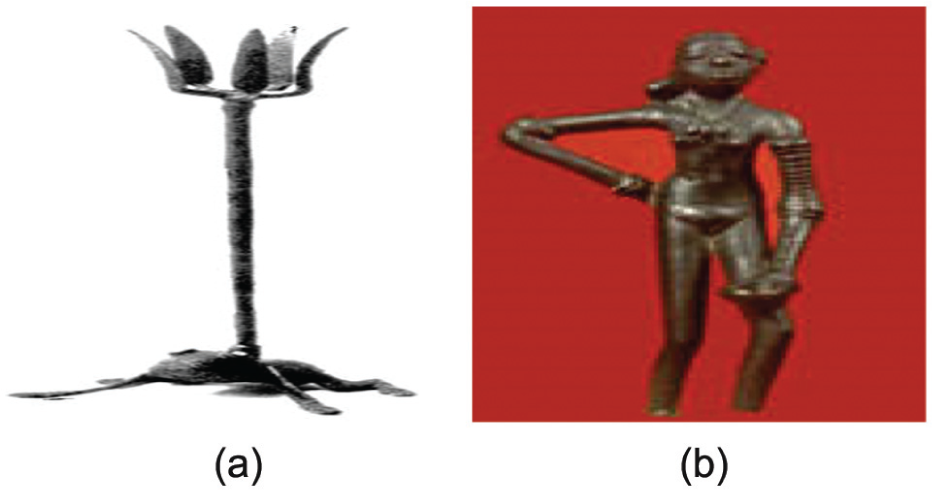
The investment casting (IC) process, often known as lost-wax or precision casting process, is one of the oldest manufacturing processes. In the time of Pharaohs, this technique was used by Egyptians to make gold jewellery of copper and bronze. IC has the capability to produce high-accuracy intricate shapes and fine impression with tight geometrical tolerance. This is an alternative approach to produce parts that are hard to machine, and there is no evidence to its origin; it is mentioned that there is no certainty of date of first step made in metallurgy and nor its location of origin, but in Iran, Syria, Palestine and even in Thailand, sharp evidence has been found. 1 Principles of IC back in 5000 BC when early men produced rudimentary items that are shown in Figure 1(a). 2 Jewellery, idols (refer Figure 1(b)) and art castings were made by IC for several centuries and various examples of such castings are still present in China, India and Harappan civilization. 3 Wax model used is coated with refractory sand to make moulds, which is de-waxed, to increase thermal strength, and afterwards, molten metal is poured. 4 Complex shapes such as turbine blades, airplane parts and modern weapons are easy to produce with this route. Furthermore, the route offers benefits such as reliability, amortization lower tooling, safe for environment and design, and casting versatility. IC reemerged in the late 19th century when the dentists begun using IC technique to make crowns, and inlays led to the invention of investment material and the invention of an air-pressure casting machine.
IC technique contributed a lot in changing and modernization of culture of people of ancient civilization (refer Figure 1(b)). IC process, as a technology, brought evolution during the Second World War in the United States as traditional tooling process was unable to meet the increased demand of war equipments, IC was used to manufacture turbine blades, aircraft engines and so on. 5
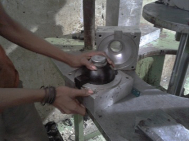
The excellent surface finish achieved with negligible metallurgical limitations extended the applications of IC to turbocharger, golf club heads, electronic part, hip joint implants and so on.6,7 Various researchers have studied that IC has come to occupy a key position in the range of modern metal casting techniques.8–12 Wax pattern is widely used in the IC but there exist some problems and technical difficulties in using it such as wax pattern expanding and ceramic shell cracking. Furthermore, with this technology, there are number of limitations where this technique lacks, such as large manual labour, precise control, size constraints and long production cycle involved. 6 A new IC technology, named freeze cast process (FCP), was suggested by researchers which demonstrated the possibility and advantage of IC with ice patterns. 13 Water drops were placed layer by layer on a platform, and temperature of platform was kept lower than freezing point of water so those water molecules condense rapidly when placed on platform. Principle steps involved in IC (refer Figure 2) that are followed in the development of spherical disc of ball valve are shown in Figure 3.14,15 Casting process in this case study started with injection of molten wax into metal die with the help of wax injection machine (step-a). Wax pattern was carried out of die (step-b) and assembled to riser (step-c), and stucco coating is preceded thereafter (step-d). Ceramic shell was then formed (step-e) and de-waxed (step-f) and baked thereafter (step-g) to increase hot strength. Molten metal was poured into the cavity (step-h), and after solidification, gate and riser were separated by manual grinding (step-j) after shakeout (step-i).
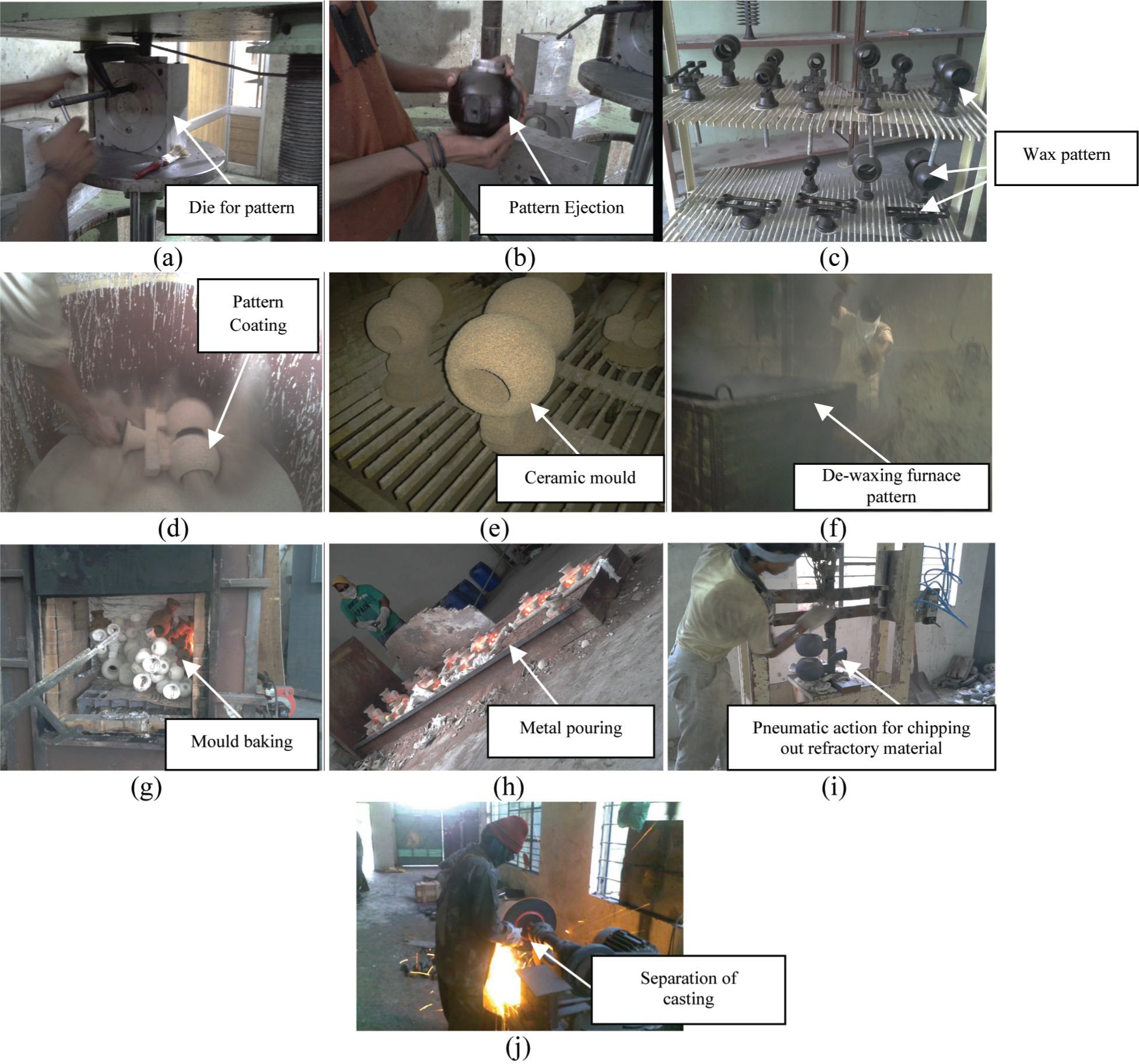
Steps involved in IC process. 14
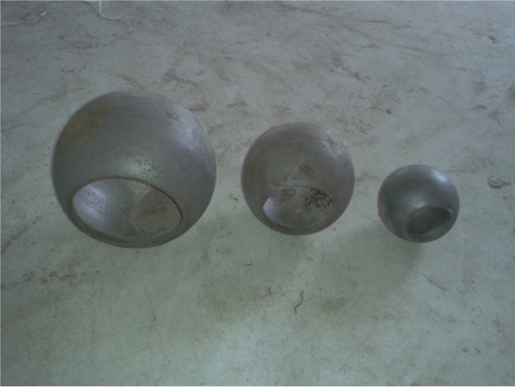
Spherical disc of ball valve. 14
Wax injection into die
Wax pattern represents the replica shape of actual part being produced by IC. Generally, molten wax at about 55 °C is injected into die by moving plunger under pressure to occupy die cavity as in step-a of Figure 2. Illustration of major properties of natural waxes by examining the presence of crystallinity through time-temperature plot discontinuities during heat transfer rate highlighted its existence. 16 Accuracy of wax patterns processed by hard and soft tooling is investigated by various researchers by varying the levels of process parameters such as injection pressure, injection temperature and holding time.17–21
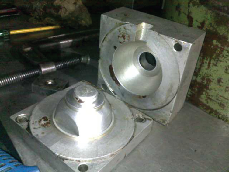
It has been found that shorter holding time resulted into more accurate pattern but difficulties emerged in removing the pattern and led to distortion. There were chances of occurrence of dimensional errors in long holding time but the span of time must be sufficient to set the wax inside die cavity accurately. 20 Accuracy of wax pattern is an important factor in precision IC as it directly affects the accuracy of cast part.22,23 Besides all factors related to pattern material, factors relating pattern die must be considered and made precisely with smooth and clear geometrical shapes as shown in Figure 4. 24
Internal machined surface of die. 24
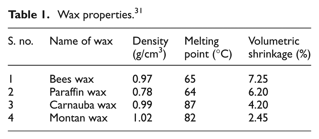
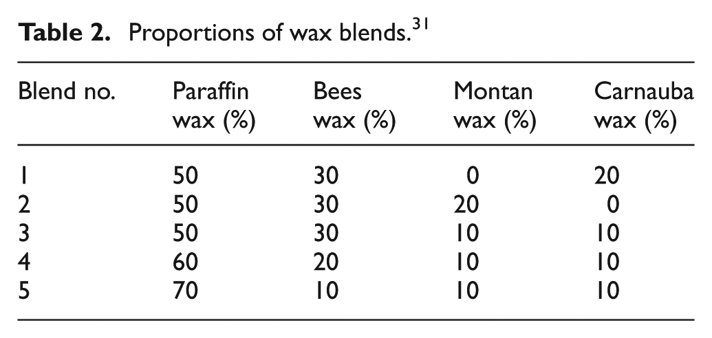
The complex mixture of wax is made of natural and synthetic compounds such as synthetic wax, solid fillers and water in small amount. Contraction/shrinkage trends for this type of wax can only be examined through thermophysical properties. 25 A new methodology to predict wax injection factors as well as shrinkage was proposed and involved the use of computer-aided heat transfer simulation. 26 Figure 5 shows the pattern thickness-temperature distribution by numerical simulation in which the threshold of the starting of contraction of a particular shape was estimated by simulation approach, and heat transfer during injection as well as contraction of wax pattern (ideal) was predicted by heat transfer simulation. Wax made of different types of blend, that is, paraffin, bees, carnauba and montan wax, was subjected to an experimental investigation to determine surface roughness and dimensional accuracy of replicas. Parameters such as wax injection temperature, holding time, die temperature and injection time were found to influence the mechanical properties of replicas. 27 But the shrinkage of blends was inconsistent in most of experimental runs; blend made of paraffin, bees, montan in the proportion of 50:30:20 showed less contraction than other proportions. 28 Wax blends with high tolerances through mixing different blends into certain proportion to improve surface finish and to reduce shrinkage.29–31 The properties of the wax (refer Table 1) in different wt% proportions of wax blends (refer Table 2) were optimized using Taguchi’s technique and MINITAB software. Use of selective laser sintering (SLS) of eucalyptus/poly(ether sulphone) (PES) blend and IC for helical gear production has been studied by various researchers. 32 SLS pattern formed with good mechanical strength was used as replica in IC to reduce production cost and production cycle. Eucalyptus/PES blend was burnt off at high-temperature roasting or low-temperature de-waxing before casting, and thermo-gravimetric analysis of SLS part was analysed through temperature graphs of wood, PES and wax in-filtered prototype; high-grade castings were produced using Wood Plastic Composite (WPC).
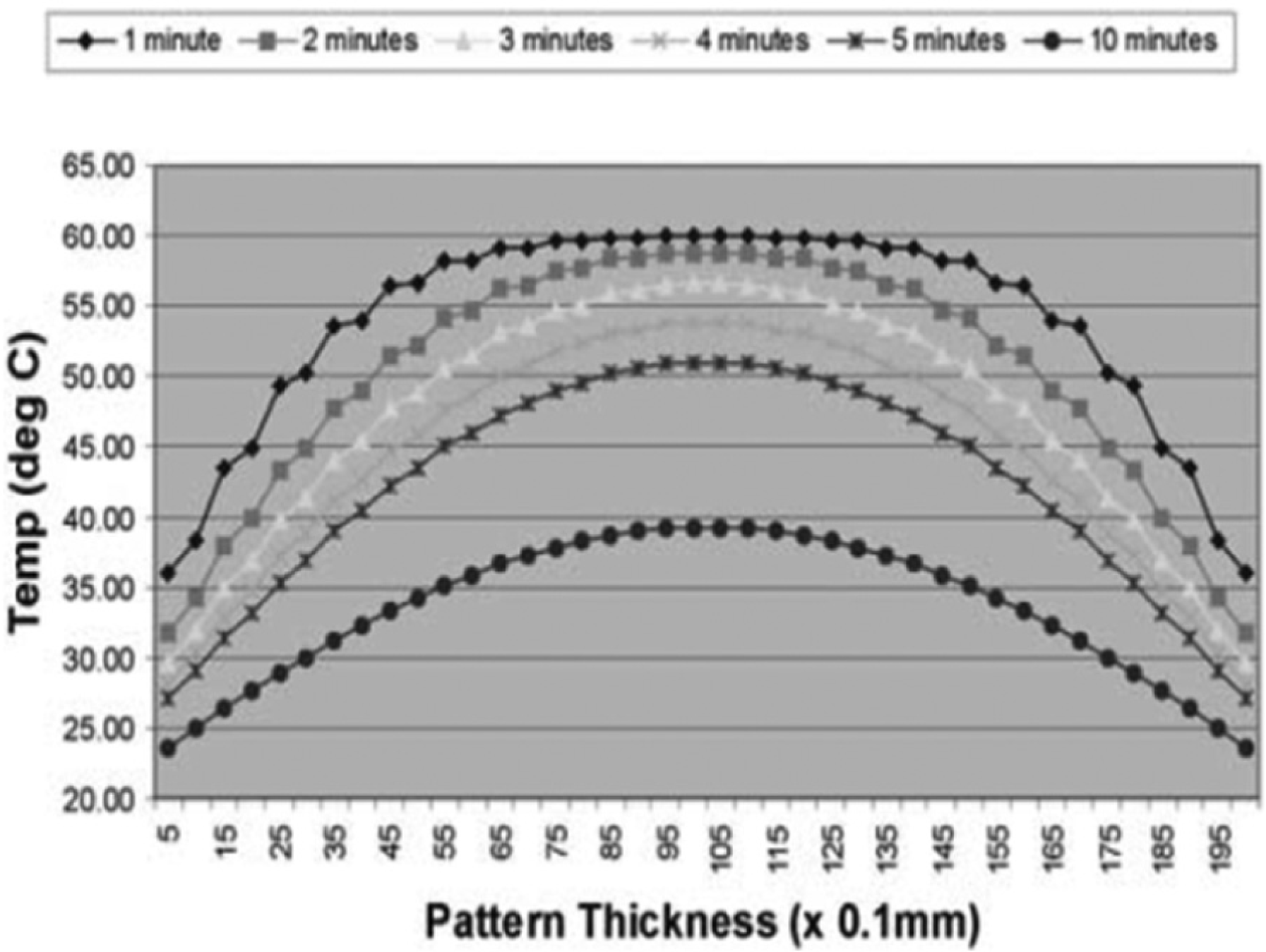
Pattern thickness-temperature distribution by numerical simulation. 26
Wax properties. 31
Proportions of wax blends. 31
Pattern ejection
Next to wax injection is the ejection of pattern out of die (as shown in Figure 6) using ejection pin provided in the die itself. Materials like stainless steel (SS) and aluminium (Al) were used most for die making due to high thermal conductivity. After injection stroke, wax pattern was carried out from die and dipped into water until it becomes harder.
Pattern ejection. 24
Tree assembly
Generally, it is not always necessary to produce complete wax pattern or pattern tree in one as the presence of die design liabilities. Usually, parts of wax replica produced separately were attached together, with a common pouring sprue and riser, individual gates, to form an IC tree. During tree assembly, minor surface fracture produced on pattern face during manual handling, and thus fractured surfaces as well as joints made should be repaired using special type of repairing wax as shown in Figure 7.
Fracture and joint repairing. 24
Shell building
Shell building often known as shell moulding or ceramic shell moulding is one of the elementary steps in IC. It involved building ceramic shell of specified thickness which is decided from the size, weight and density of the metal to be poured. Strength of ceramic shell is a critical requirement, 33 and at the same time, other properties of refractory to be considered before selection of moulding material are as follows: (1) adequate green strength, (2) sufficient baked strength, (3) refractory permeability, (4) light in weight, (5) collapsible after casting, (6) good surface finish of shell, (7) adequate tensile strength, (8) flow ability, (9) collapse ability and (10) reusability. Design of stucco coating plays an important role in IC as numerous output properties of casting depend upon the characteristics of ceramic shell. The process of shell building starts with slurry coating which acts as a binder consisting of zircon flour, colloidal silica, ethanol, triton and distilled water rotated in a drum. It was investigated by some of the researchers that use of more than one binder during moulding has significantly improved the mould properties. 34 The very first coating on pattern is made of zircon flour of finest grain size and allowed drying under controlled environment conditions for sufficient time before next coating. Coating and drying is repeated over and over until desired mould thickness has been attained. 35 Ceramic slurry and other moulding ingredients affect the output properties of casting, and optimization of such process variables should be made to satisfy industrial demand, globally. A good slurry composition will not be guaranteed to produce defect-free and smooth casting. 36 Many researchers explored the role of refractory primary slurry in ceramic shell IC process.37–39 Material used in ceramic shell consists of binder, refractory fillers and additives, and ethyl-silicate-based slurries have short life and are time-dependent, while colloidal silica is a water-based binder in an aqueous suspension of silica. 40 A hydrolyzed ethyl silicate was introduced in IC, 41 and using exclusion chromatography, the lower and upper limits on the molecular weight of ethyl silicate hydrolysis products were determined at which no flaws were formed in complex geometric planes and surfaces of investment shell moulds. Although zircon flour is costly, it has been used as primary slurry layer. Parameters like viscosity and plate weight of slurries were discussed, and scanning electron microscopy (SEM) technique was used to study the surface morphology of shell prepared using different levels of zircon flour, fused silica, filler/sol ratio and catalyst. 42 Physical properties of primary slurry were crucial to the surface quality of the finished castings, and binder influenced the physical properties of primary slurry for titanium casting. Parameters such as viscosity, bulk density, plate weight, suspensibility, gel velocity and strength were compared for different zirconia-based binders whose physical properties are shown in Table 3, and 2.5:1 powder/binder ratio was found promising to superior surface quality. 43
Physical properties of binders. 43
Slurry layer combination was found to affect the output properties of final casting. 44 IC process parameters such as shape factor, slurry layers (mould thickness) and pouring temperature were studied to identify the main factors controlling surface hardness, dimensional accuracy (Δd) and surface roughness (Ra) of castings produced using aluminium, mild steel and SS.45,46 Analysis showed 0.70%, 16.80% and 47% of surface hardness, surface roughness and dimensional accuracy contribution of slurry layers, respectively. Taguchi’s L9 orthogonal array (OA) was used to optimize properties such as surface roughness, hardness and dimensional accuracy of spherical disc. Slurry coatings were made on wax pattern (refer Figure 8) by varying the tertiary and quarter layers, and signal-to-noise ratio was used to represent response characteristics (given in Figure 9) and concluded that layer combination contributes 0.43% in hardness, 34.06% in surface roughness and 6.57% in dimensional accuracy of spherical disc of ball valve.
Slurry coating on spherical disc. 24
Variation of S/N ratio and (a) micro-hardness, (b) surface roughness and (c) dimensional accuracy with respect to layer combination. 24
Various chemical reactions occurred during casting process, and researchers investigated in one of the studies that interfacial reactions occurred during casting between Ti-46Al and ceramic shell mould made of ZrO2 and Al2O3 resulted into a reaction layer of 230 µm in the case of the zirconia mould, whereas there was no visible reaction layer for the alumina mould. Electron probe microanalysis indicated that elements of the two kinds of shell moulds diffused into the alloy melt during casting but to different extents. 47
Advancements in shell moulding
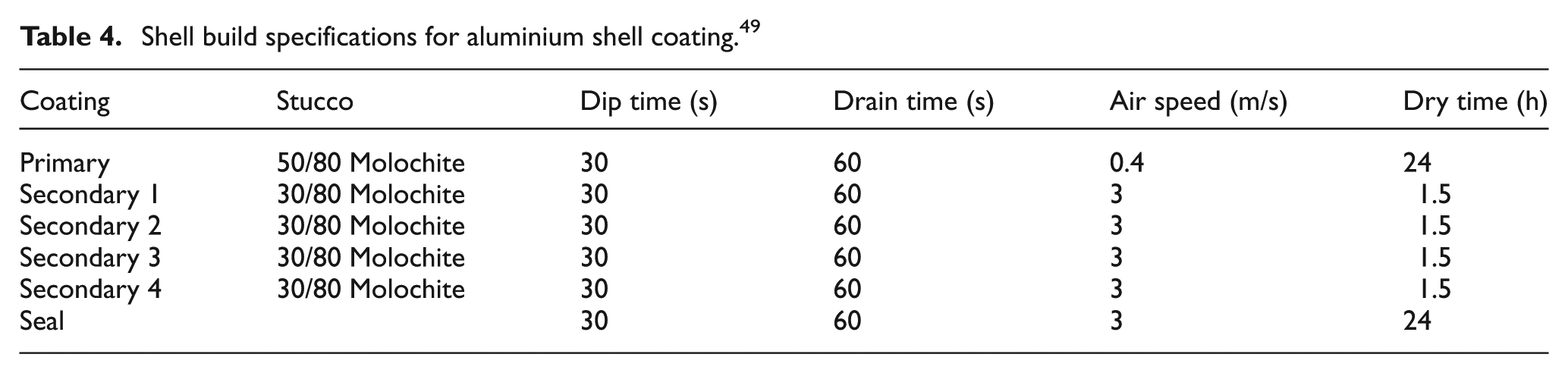
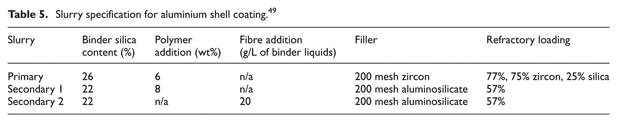
Although IC process serves global needs by producing parts with variety of metals and alloys, yet certain limitation needs immediate attention of researcher. Problems associated with shell cracking and permeability of the ceramic mould while metal pouring lead to surface defects (blow holes) and porosity always present during casting of high-temperature metal. Furthermore, problems associated with ceramic shell ingredients have been exacerbated preceded in the Environment Protection Act, 1992, and limited the degree of emission and increased the use of water-based shells especially in the UK industry. These water-based shells are not all set and seek for the need of gellation by moisture removal. The range of alloy’s cast, size and complexity and requirements of cast component lead to the use of special materials as an ingredient to shell moulding material. 48 Ceramic shell using polyvinyl alcohol (PVA) and nylon fibre has been developed (refer Figure 10) for primary slurry layer and compared green and baked strength of two.49,50 Good surface finish and shell strength during Al casting were achieved with specifications shown in Table 4 using filler materials of 200 mesh or combination of 200 and 325 meshes for slurries (refer Table 5).
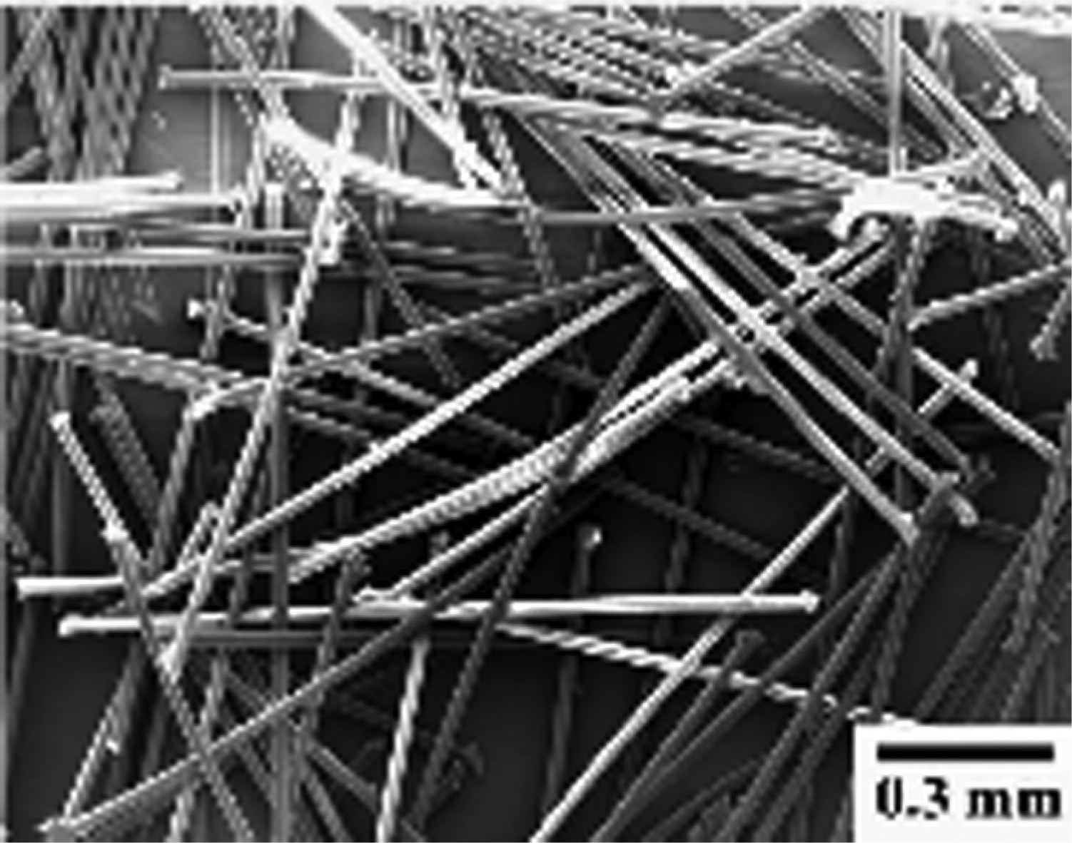
Scanning electron microscopic image of nylon fibre. 49
Shell build specifications for aluminium shell coating. 49
Slurry specification for aluminium shell coating. 49
Green and baked strength (shown in Table 6) of shells was also improved and using nylon fibre shell, thickness increased by a factor of 15% compared to polymer shell, and permeability increased by a factor of 3. Yttria is an important primary coat material in investment shells for casting extremely reactive Ti-Al alloys, and polymer is usually added to slurry to improve the strength of the shell. In this investigation, polymer content varied through 0%, 6% and 30% and samples were sintered at 1000 °C, 1200 °C and 1400 °C. Silica from the backing coat was seen to travel through the primary coat and diffused into the alloy regardless of the shell system. Higher mould permeability was observed in the mould containing higher polymer level, and this was found to be advantageous for complete mould filling.51,52 Crack resistance of ceramic shell by introducing Al silicate fibre having diameter ranging 5–25 µm and length of 1 mm (SEM image of silicate fibre is shown in Figure 11) can be improved by dispersing it uniformly in ceramic shell. 53 It was observed from Figure 12 that when the sintering temperature was set at 100 °C, tensile strength was shown by ceramic mould and increased as the temperature rises. Whereas tensile strength increased linearly as vol.% of fibre increased. Generally, the addition of such fibres results into increase in the brittleness at the expense of elongation and ductility of the mould. So, there are chances that the mould may fail or crack due to thermal shock. Furthermore, the effect of addition of short fibre and polymer in moulding slurry on mechanical properties of ceramic moulds both at green and baked conditions resulted into improvement in casting qualities. With an addition of silicate fibre (in increasing order, that is, 0–0.24 vol.%), the tensile strength increased from 0.175 to 0.236 MPa and shrinkage rate decreased from 1.75% to 1.68% (at sintering temperature 400 °C). Influence of the use of binder hydrolysis to prepare moulds sintered from 100 °C to 800 °C on tensile strength and shrinkage rate was investigated. 54
Strength results for shell sample. 49
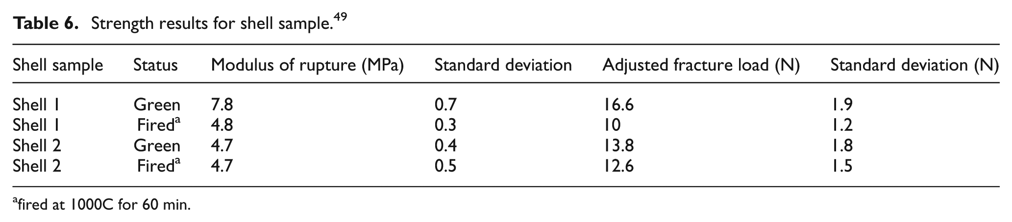
fired at 1000C for 60 min.
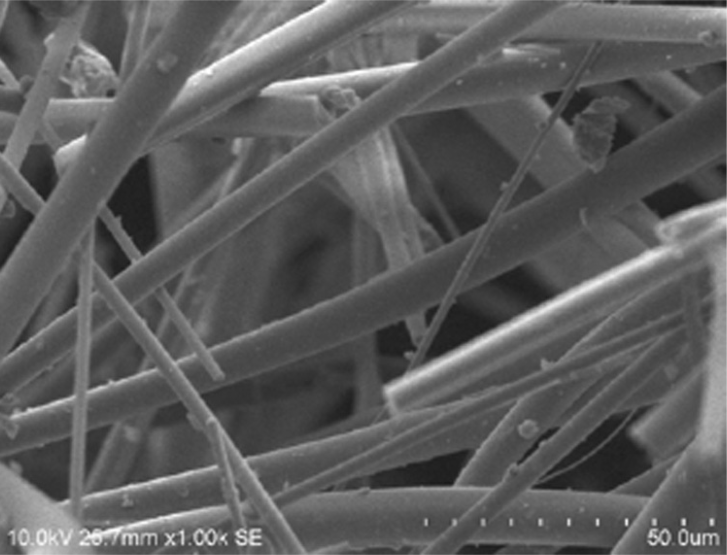
SEM image of silicate fibre. 53
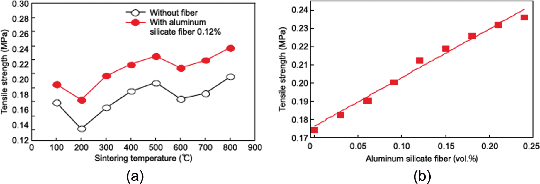
(a) Effect of sintering temperature on tensile strength of ceramic mould and (b) effect of fibre content on tensile strength of ceramic mould sintered at 400 °C. 53
In a case study of development of hip joint using nylon fibre of 1.5D (Daniel) and of 1–2 cm length with colloidal silica (binder) used as refractory reinforcement was stirred continuously in slurry tank. Percentage contribution of input parameters such as number of layers, pattern material and nylon fibre addition in 1°-2°-3° layer on micro-hardness, surface roughness and dimensional accuracy of hip joint of Al was found through experimentation and surface morphology (shown in Figure 13.) was used to study the surface characteristics of casted hip joints. Specimens with larger grain growth were found having more hardness than specimen with smaller grains, and addition of nylon fibre dramatically increased the fired permeability due to porosity networks created by burnout fibre. Modified shells with much reduced drain time gave a higher ceramic retention rate after dipping and led to a thicker coat compared to that produced without fibre addition. 55 Rate of heat transfer plays a prominent role on hardness of castings, and with simulation modelling, it is now possible to predict heat transfer trends of IC. 56 Researchers undertook an investigation to develop stable and cheap refractory slurry systems, suitable for use as a face coat in the IC of titanium aluminides (Ti-Al-O) and compared with traditional yttria-based face coat slurry. The reactions occurred have changed the wetting behaviour of the Ti-Al on the Ti-Al-O face coat with the contact angle decreasing as a function of interaction time. 57
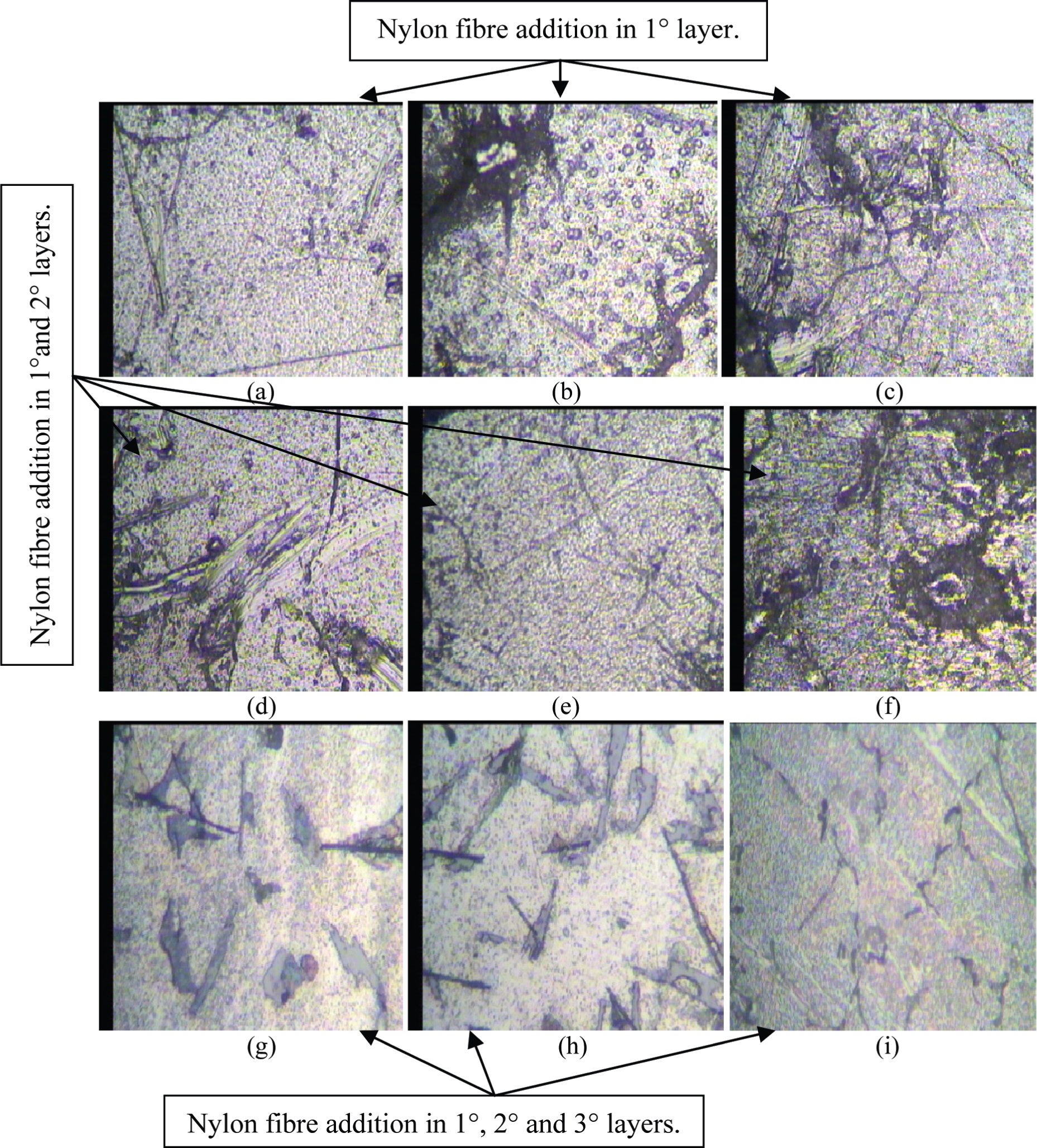
Microstructure of hip joint. 55
De-waxing
To produce ceramic shell cavity, ceramic mould is de-waxed by heating it at reasonable temperature which allows the wax melt out. This process is also known as autoclaving. Generally, in small-scale casting industries, pattern tree is placed at a temperature of 180 °C–200 °C for about 15 min in furnace of molten wax, as shown in Figure 14. Pattern tree is then taken out of the furnace with clean cavity inside, but one of major disadvantages of this process is non-recyclability of wax as refractory particles mix with virgin wax and affect the chemical properties of virgin wax. Various researchers suggested different approaches of de-waxing for recyclability of wax, to reduce the chance of shell crack and to reduce cost and labour expense. This method of autoclaving leads to shorten life cycle of wax due to the introduction of refractory particles, which affects wax properties. Problems in autoclave de-waxing can be avoided using alternative approach of flash fired furnace comprising a heat chamber, and inert gas like carbon dioxide was injected into extinguish chamber which cools wax flaming to reduce dripping into chamber. 58 Mostly, wax recovered after autoclaving contaminates due to the incorporation of dirt particles. The wax traces retained on the inner-most surface of the mould did not accomplish complete wax removal. 59
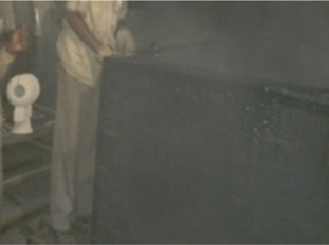
De-waxing furnace. 46
Wax is a dielectric material and can be heated using microwave. Today, microwave de-waxing is broadly used in industries which help investment casters not only in a way to recover melted wax but also offered a better product quality. Research in area of autoclaving is less explored but some researchers tried to increase wax life using alternating routes. A project dealt with microwave de-waxing applied to IC process has been undertaken by Brum. 60 Samples of autoclave and microwave de-waxing were tested in terms of their refractory index, volumetric expansion and shore hardness of wax. Figure 15 shows that the characteristic peaks using infrared spectra in 12-cycled microwave wax and 12-cycled autoclave wax strike at 2922, 1459 and 724 cm−1 related to paraffin fraction and 2922, 1936 and 1282 cm−1 related to acid fraction. De-waxing approach should be made in a way that recovered wax should contain no impurities and recycled maximum time. Different ways through which pattern properties (such as surface finish and dimensional accuracy) could be enhanced by properly controlling the injection processing parameters were thoroughly discussed. Investigations made on incorporation of nylon fibres and polymer additions confirm that a ceramic shell reinforced with nylon fibres attains additional permeability compared to the one with polymer additions. Different investigations carried out on autoclave de-waxing and microwave de-waxing conclude that the wax properties were less altered with microwave de-waxing when compared to an autoclave de-waxing.
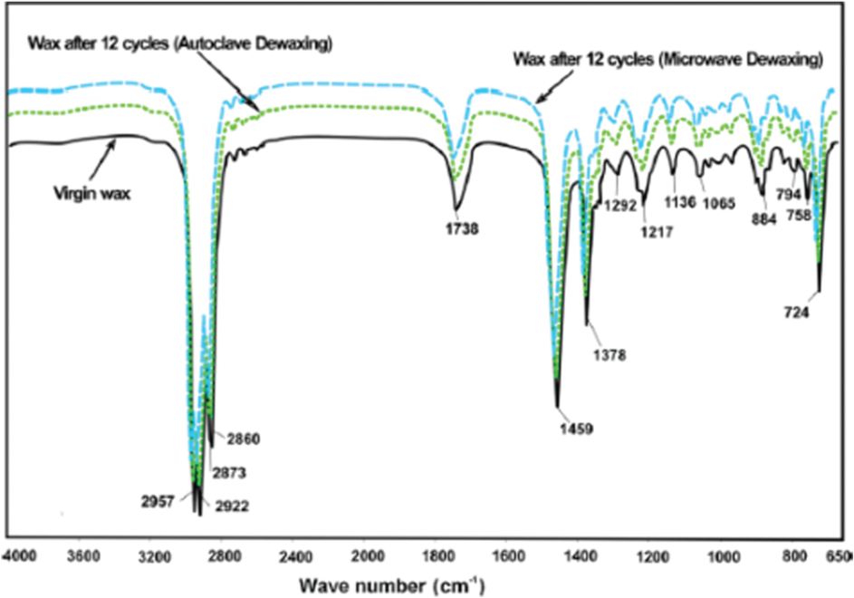
Infrared spectra of virgin, 12-cycled microwave and 12-cycled autoclave wax. 60
Baking
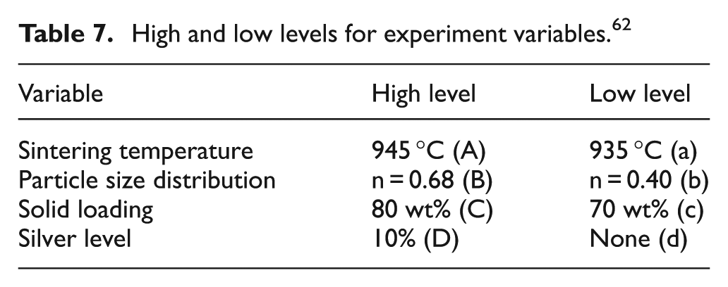
Baking or preheating is a process in which sand moulds are baked at a temperature about 950 °C–1100 °C in diesel/electric furnace for 25–40 min as shown in Figure 2 (step-g). Basically, baking is a process for increasing the dry strength of the mould and to evaporate the residual traces of wax and unwanted moisture particles. Baking reduces the chance of shell cracking occurred due to the difference in temperature of mould and pouring metal. The effect of preheat temperature and preheat time has been investigated on mechanical properties of A713 alloy IC using Taguchi’s L9 OA to find out the effect on hardness, impact strength and tensile strength of castings. It was found that the hardness of castings was increased by increasing the preheat temperature and showed increasing and decreasing trends with the increased mould preheat time. Impact strength was decreased by increasing the preheat temperature and showed mix response for increased preheat time. Furthermore, tensile strength decreased with increasing preheat temperature and increased preheat time resulted into mixed response of tensile strength. 61 Many researchers (Hooker et al.) have manipulated density, porosity and critical current density of fired ceramics choosing four variables: sintering temperature, particle size distribution of YBa2Cu3O7x powder, solid loading of the slip and silver dopant level, as shown in Table 7. Analysis of variance results indicated that porosity and density were highly dependent upon particle size distribution, and 15% porosity was increased by sintering at 935 °C for 8 h. 62 Investigation has been made to determine the thermal boundary conditions that exist during the solidification of metallic alloys in IC. Quantitative information about these conditions was used in their research to produce accurate results, and the method used involves application of a new inverse heat conduction method for thermal data recorded during laboratory experiments of aluminium alloy (A413, A356, A319 and commercially pure Al) solidification in IC shell moulds; the resultant heat transfer coefficient (HTC) for the alloy/mould interface was calculated. 63
High and low levels for experiment variables. 62
Metal pouring
Pouring is processed immediately after baking or preheating of ceramic shell. Metal is melted at pre-decided pouring temperature and poured into the mould cavities (shown in Figure 16). Pouring temperature should not be too high because it will crack the ceramic shell and not too low, as it results in unsound castings. Effect of pouring temperature on mechanical properties, such as hardness, impact strength and tensile strength of A713 alloy, is illustrated in Figure 17. 61 It was identified using signal/noise ratio that type of metal contributes about 99.28% in hardness, 49.66% in surface roughness and 68.38% in dimensional accuracy. 46
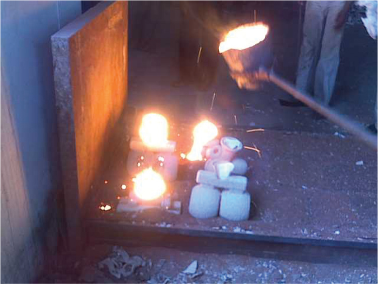
Metal pouring. 46
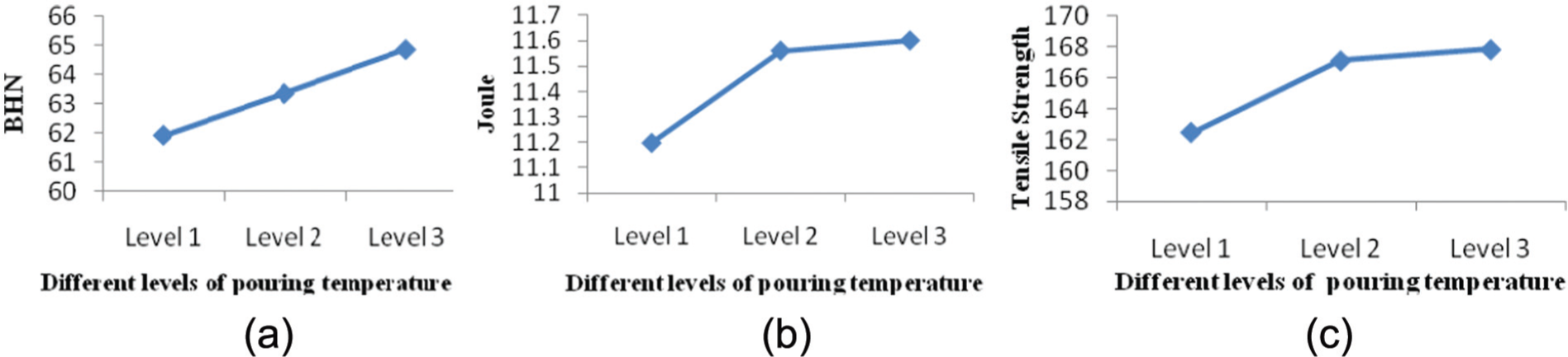
Variation of (a) hardness, (b) impact strength and (c) tensile strength with respect to level of pouring temperature. 61
Researches on simulation of heat transfer time in IC to reduce cracking rate of the mould were also made, 64 and it has been seen that the casting surface was damaged due to the reactions of metal with its atmosphere during the early stages of cooling. While it was claimed that casting surfaces can be secured for ferrous objects by filling a gas-permeable refractory shell mould with molten ferrous metal, the said metal was molten immersing a substantial portion of said filled mould in a bath of molten aluminium below the melting point of the poured ferrous metal. 65
Knockout
Knocking, shakeout or chipping-out of refractory is performed after metal solidification. Layer of ceramic refractory can be chipped out manually or performed on pneumatic vibration machine as shown in Figure 2(i). Riser and gate of the casting tree are separated to get final part. This step should be performed safely to reduce post-machining expenses. Collapsibility of refractory should be high and knocked out easily after solidification, but impurities and lack of refractory properties lead to obstacles in shell removal; however, it was realized that adding alkali salts to earth metal facilitates easy removal of shell.66,67
Rapid prototyping technique
Production of wax pattern in conventional IC involved high tooling cost and longer production cycle. Depending on the geometry and complexity of the part, it takes from 6 to 12 weeks. Furthermore, wax pattern in traditional IC suffers from contraction of pattern and limited mechanical strength. Using rapid prototyping (RP), a plastic/polymer/wax pattern is substituted for conventional wax pattern with advanced mechanical properties. If the production volume is lower and only few samples of metal pieces are needed, RP technology can be used. For large number of very small patterns, other technologies can be applied to IC. 68 RP in collaboration with IC is not limited to its industrial applications but extended to medicine engineering and metal matrix composite (MMC). Rapid prototyping techniques (RPTs) have different classes as shown in Figure 18. 13 The importance of RPT integrated with IC has been discussed in this section. Besides all RP techniques, SLS, fused deposition modelling (FDM), stereolithography (SLA) and laminated object manufacturing (LOM) are the techniques used mostly by researchers. Each technique has its own area of advantage and limitation. 69 FDM process is found to be the most promising as it has significant advantage in terms of the elimination of expensive tooling, the flexibility and the possibility of producing very complex parts and shapes. It tends to prove that FDM process offers time and cost advantages over conventional technologies and is the second most widely used RPT, after SLA, which showed its versatility over SLA in the field of IC. 69 Steps involved in creating a physical prototype are as follows: (1) create a computer-aided design (CAD) model of the design, (2) convert the CAD model to Standard Triangulation Language (STL) format, (3) slice the STL file into thin cross-sectional layers, (4) construct the model one layer atop another and (5) clean and finish the model. FDM (schematic view shown in Figure 19) system was developed by Stratasys Inc. Acrylonitrile butadiene styrene (ABS), the first material commercialized by the manufacturer, has all the properties which enable its services in IC. The material in the form of extruded slices is laid down on the platform base, layer by layer, from the nozzle.
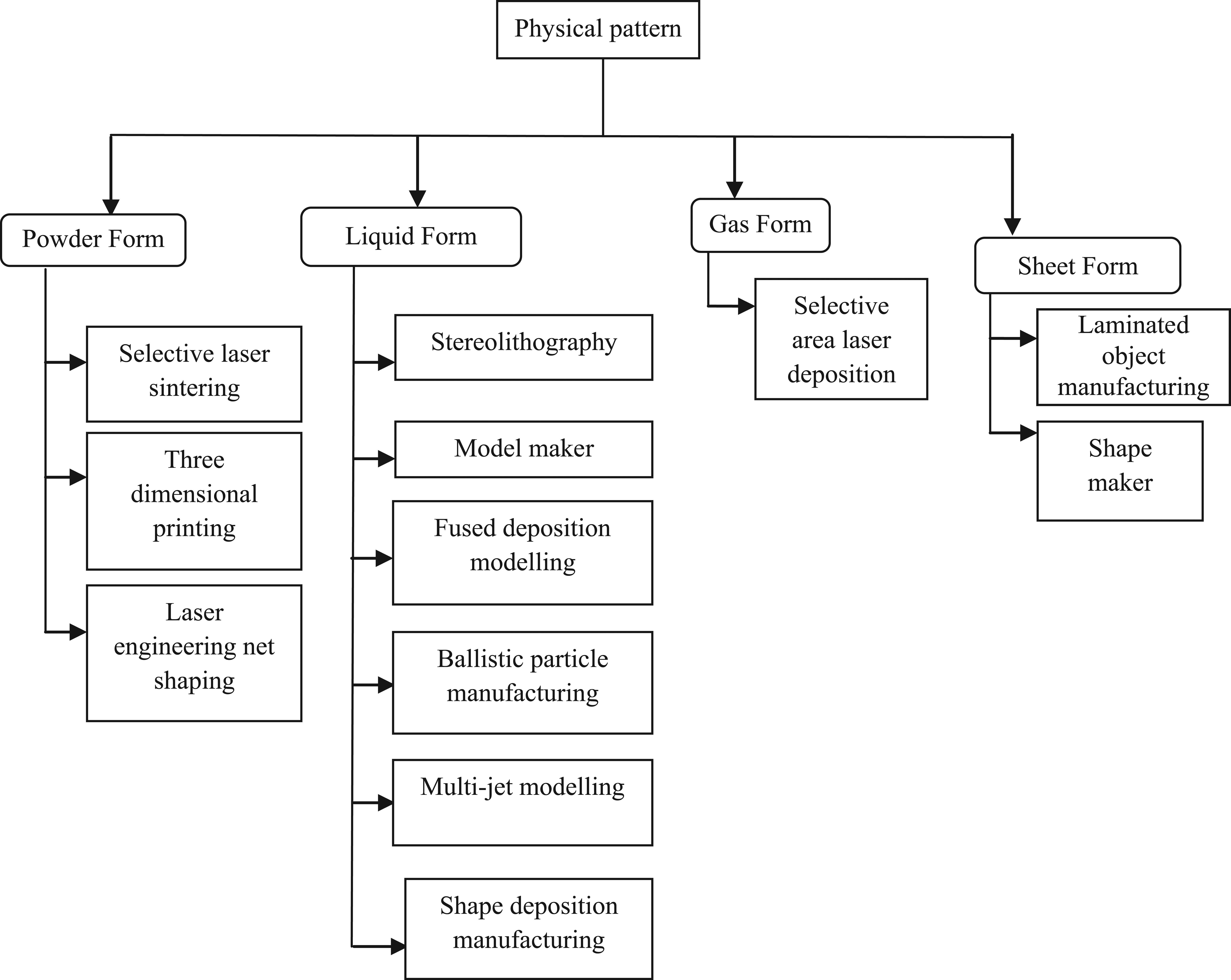
Rapid prototyping process classification. 13
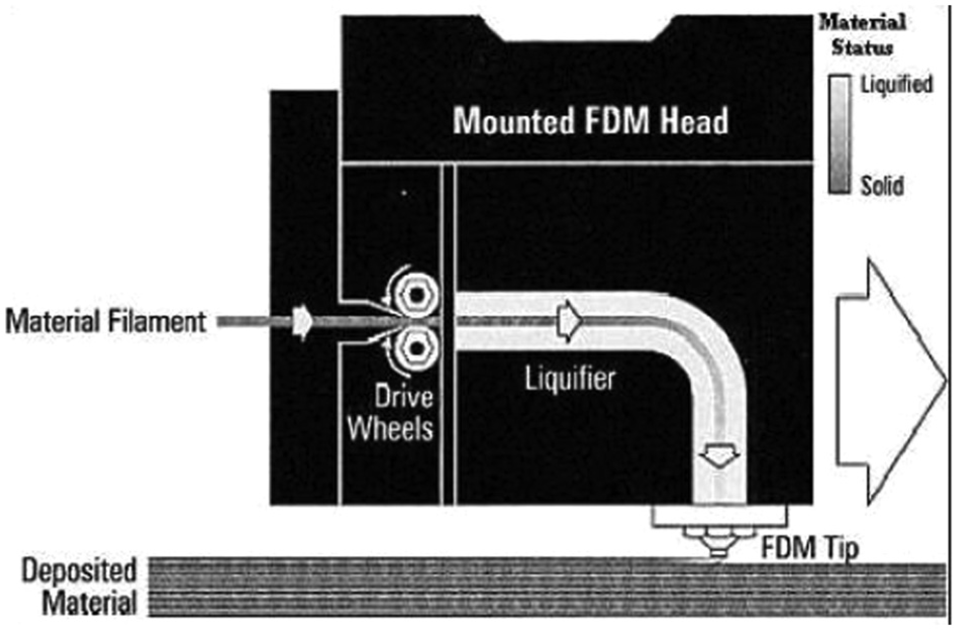
Schematic of FDM. 70
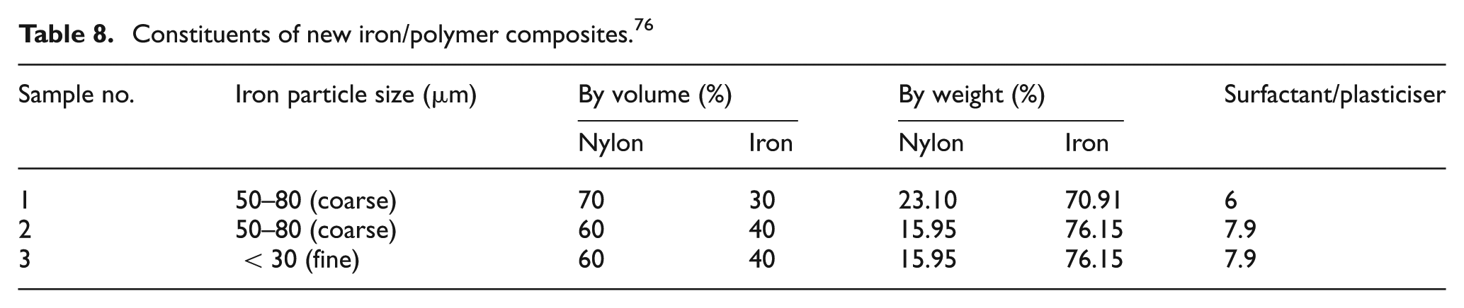
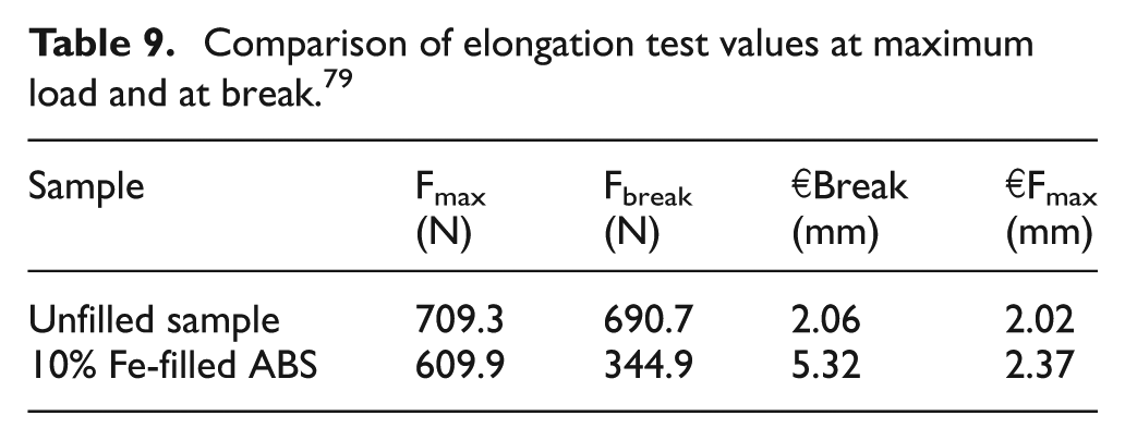
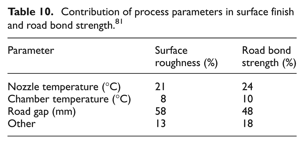
Omar et al. studied the differential ceramic shell thickness evaluation for direct rapid IC (RIC) with an aim to compare the efficiency of different shell thickness for aluminium casting part fabricated from ABS and acrylate-based material made with FDM and multi-jet modelling (MJM), respectively. The hollow RP pattern was used directly to produce ceramic moulds as feasibility of ceramic mould was assessed in terms of burnout ability and crack defect. Result showed that thicker mould with proposed stucco procedure resulted without any crack defect for both RP parts and no residual ash remained when firing at a temperature of more than 870 °C. FDM produced better accuracy for overall mould thickness than MJM. 71 Studies on optimization of process parameter FDM-fabricated parts using Taguchi’s approach were carried out to improve FDM abilities under different applications considering the major industrial concern, that is, reduction in product development cycle time. 72 The quality of FDM-fabricated parts was significantly affected by various process parameters used in this process. So, it is necessary to optimize the process parameter of FDM to improve the quality of the parts so that best results can be obtained when used as a sacrificial pattern for IC. A similar attempt has been made with FDM technique for getting physical part in ABS polymer from CAD data and using it as pattern for IC. 73 Feasibility of manufacturing the customized/tailor-made part using FDM was the main focus, and experimentation was carried out to develop mathematical model to minimize the defects in casting. It was concluded that zero-defect casting is possible using mathematical model and simulation software to design correctly the gating and riser. For exploring abilities of FDM process, work for the development of new metal and ceramic-based material has been in progress for rapid fabrication of functional component by FDM with higher mechanical properties, 74 and outstanding manufacturing capabilities of RP and rapid tooling technique (RTT) are exploited to provide cost-effective solutions for low-volume IC runs as RP parts were substituted traditional wax pattern for IC and can serve as production moulds for wax injection moulding. 75 Application and potential reviewed the concepts, strengths and weaknesses of RPT techniques in IC. Many researchers worked on the development of feedstock filament of FDM so that besides cast factors, properties of prototype can also be improved. A similar work was carried out to develop metal/polymer composite material for FDM (shown in Table 8) with an aim to direct rapid tooling using iron particle in nylon-type matrix in suitable proportion. 76 However, work on development of new metal polymer composite consisting of an FDM-grade ABS containing 10% fine iron particles by volume was experimentally investigated, and the mixture of 10% iron powder and 90% ABS powder by volume prepared in screw extruder machine was found to have high values of mechanical test.70,77 Figure 20(a) shows metal/polymer-based FDM feedstock filament, and Figure 20(b) shows test sample produced on FDM3000 from new iron/ABS composite (black colour) and unfilled ABS (white colour). A numerical and experimental study of fracture on epoxy web RP-SLA patterns during the burnout process of IC process has been carried out. 78 Shell fracture was avoided by buckling and crazes fracture of the epoxy-webbed pattern in early stages of the burnout. Thermal and mechanical properties of metal-particle-filled ABS composites for FDM application have been investigated where a test sample made of iron/ABS and copper/ABS mixed by centrifugal grinder was extruded in screw extruder machine, and both filled and unfilled ABS wires were tested for its elongation (refer Table 9). There are many obstacles in the development of FDM feedstock wire such as composition having relative melt flow index, uniform distribution of filler in plastic and extrusion of continuous wire. 79 The main obstacle for the application of new materials with specific characteristics often came from the use of intermediate precursors such as a filament, and problems were encountered during the preparation of new feedstock filament due to the use of precursor filament. 80 Principle of polymer extrusion, called extruder deposition process (EDP), which deposits material on a computer-controlled positioning system to build components, was investigated to study the effect of variables such as nozzle temperature, chamber temperature and road gap on road bond strength and surface finish. 81 Percentage contribution of each parameter on road bond strength and surface finish is given in Table 10.
Constituents of new iron/polymer composites. 76
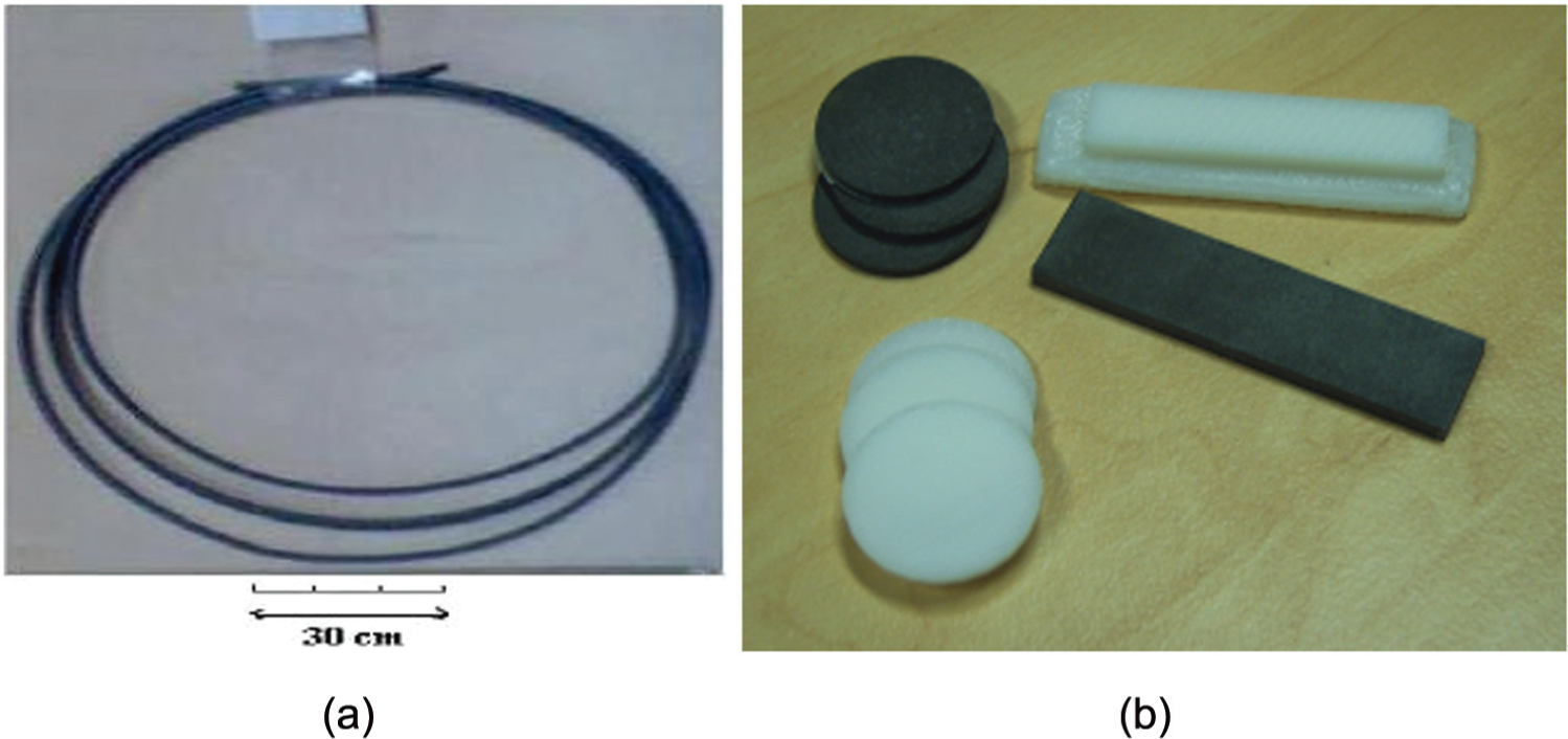
(a) Metal/polymer-based FDM filament and (b) test sample produced on FDM3000 from new iron/ABS composite and unfilled ABS. 70
Comparison of elongation test values at maximum load and at break. 79
Contribution of process parameters in surface finish and road bond strength. 81
Surface roughness of replica produced with FDM process is high due to staircase effect involved in layer manufacturing. This is one of the reasons why foundry engineers are not adopting this technique in job or batch productions. An approach to determine the optimal part deposition orientation for FDM process by considering two contradicting objectives, namely, build time and average part surface roughness, has been suggested by various researchers. 82
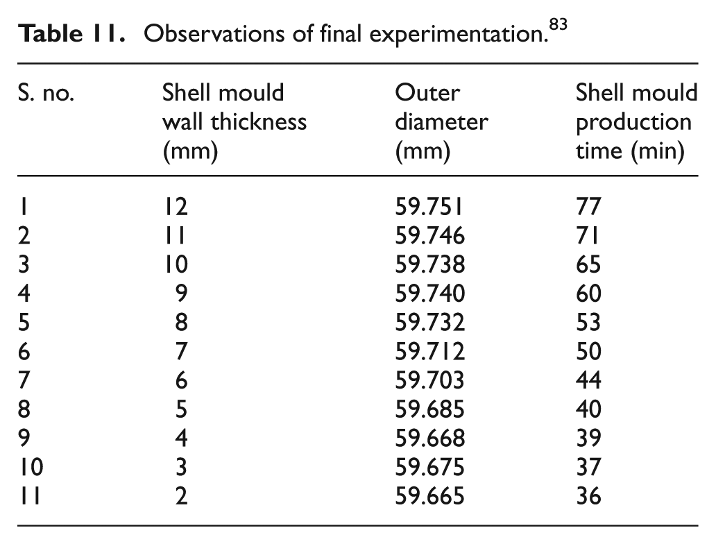
Integration of FDM and IC process has become one of most advance techniques for manufacturing high-quality castings quickly and economically. Production of sacrificial pattern through RPT for IC is known as RIC. A very new technique Z-Cast was analysed for its process capability of Z-Cast direct metal casting (three-dimensional rapid casting (3D-RC)) technique by producing optimum shell wall thickness of shell mould in Al casting. Shell mould wall thickness was reduced significantly from 12 to 2 mm and reduced production time too in casting as shown in Table 11. Z-Cast-501 is one of the latest approaches of rapid casting (RC) for direct fabrication of patternless moulds for sand casting as shown in Figure 21(a). 3D-RC process started with CAD model of benchmark, and shells were designed by UNIGRAPHICS Version NX 5, converted into STL format and fired on 3D-Z-510. Solidified Al castings in shell mould are shown in Figure 21(b), and final castings are shown in Figure 21(c). It was analysed that tolerance grades obtained were acceptable as per ISO standard UNI EN 20286-I (1995), and ‘Cp and Cpk’ values for outer diameter were greater than 1. 83
Observations of final experimentation. 83
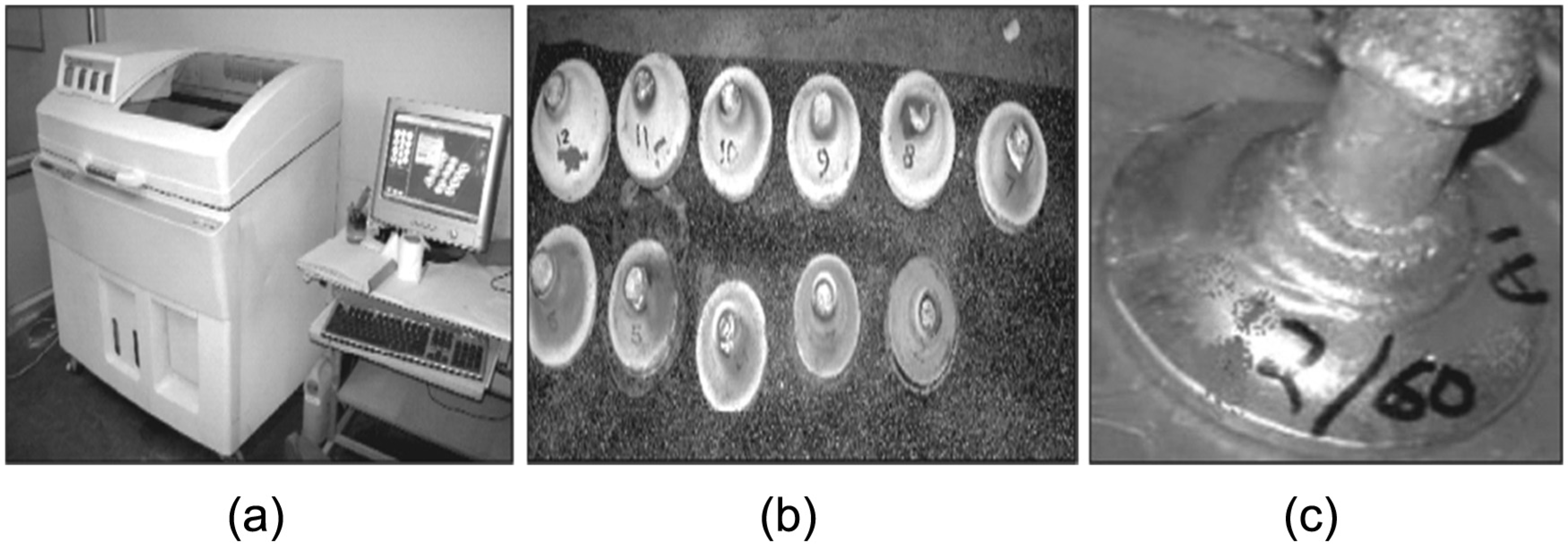
(a) 3D printing (Z510) machine used for making shell mould, (b) solidified aluminium castings in shell mould and (c) final casting. 83
Some studies have highlighted an alternative route of producing MMC using hybrid casting route, that is, combination of vacuum moulding (VM), stir casting (SC) and RP.84,85 The pattern diameters were taken as 50, 60 and 70 mm and thickness of pattern was 25, 30 and 35 mm. 3D view of master pattern is shown in Figure 22(a). A typical setup of VM is shown in Figure 22(b). The contribution of input parameters to hardness (HV) of casting was found as 73.06% composition, 2.00% grain size and 23.06% vacuum pressure. In case of surface roughness (Ra), the contribution was 29.97% composition, 26.05% grain size and 38.49% vacuum pressure. Similarly, for dimensional accuracy (Δd), the contribution was 64.07% composition, 12.38% grain size and 21.13% vacuum pressure.
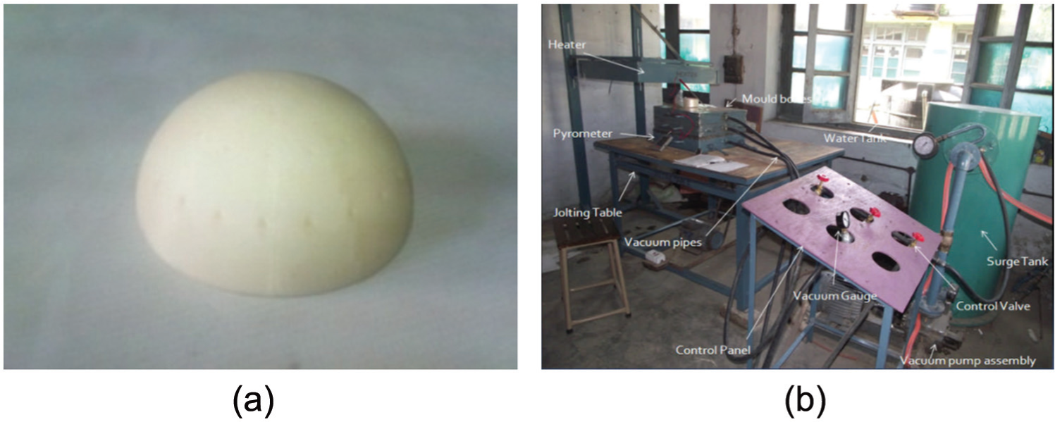
(a) 3D view of pattern and (b) VM machine. 85
Optimized setting of input parameters for maximum HV was at Al-5%SiC composition, 0.04 N/mm2 vacuum pressure and 50 grain size; for minimum Ra was at 70 grain size, 0.05-N/mm2 vacuum pressure and Al-10%SiC composition; and for minimum Δd was at Al-5%SiC composition, 70 grain size and 0.04 vacuum pressure. Recently, a patent has been filed that claimed to produce MMC through FDM-based IC route using hybrid filament for preparing sacrificial pattern. 86 Characterization of such claims must be carried out in order to check the promising level of the claim in various industrial applications.
Biomedical applications of RPT
Perhaps the most obvious application of RPTs as a medium is to design and develop medical devices and instrumentation. This is simply an outgrowth of the engineering applications of this technology. Any field where its imperative is to decrease product development time, it enables the users with functional performance feedback as an excellent prospect for RP. Nowadays, RPT concept is growing significantly since one of the new perspectives of manufacturing is to save material and energy. 87 Medical models often produced by RP technology are also referred to as layer-based manufacture or solid freeform fabrication (SFF). RP process involves conversion from 3D CAD virtual models into physical prototypes of human implants without the need for specialized expensive tooling. Process is accomplished by breaking the 3D computer model into series of slices having finite thickness. 88 An RP machine fabricates each of these slices in turn and joins them together. Fabrication of biomedical implant is a tailor-made process, which means size, geometry and attributes of joints or implant vary with person to person. Medical implant fabrication starts with magnetic resonance imaging (MRI) or computerized tomography (CT) scan of patient, and then CT or MRI scan is converted into 3D geometry using MIMICS or 3D-Doctor software package, which is fired to RP machine (refer Figure 23). 89
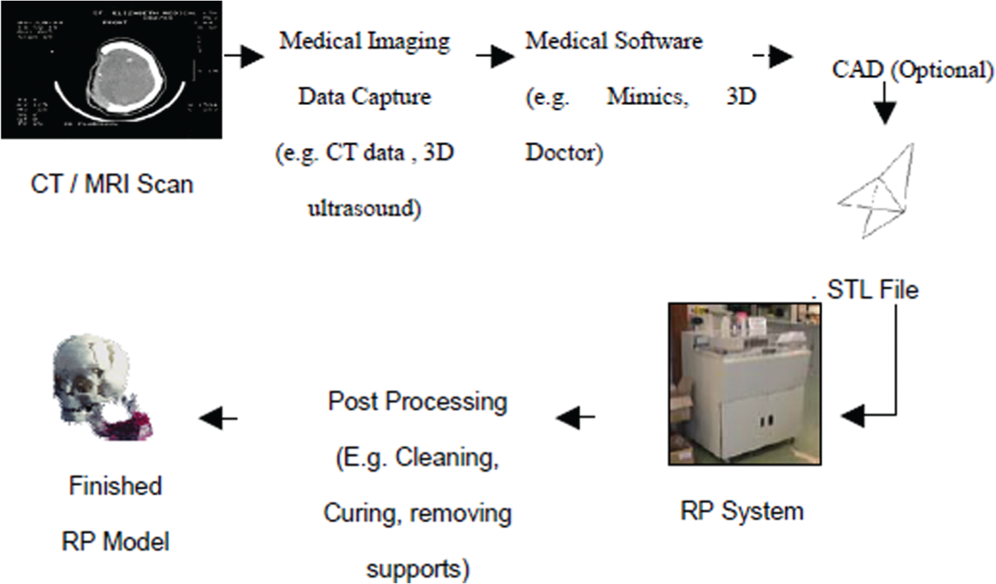
Generalized procedure for creating medical models. 89
Layers of refractory sand are made on the finished pattern to prepare shell mould. The cavity for pouring molten metal is produced once pattern material is burned out. RP and IC undoubtedly is a useful aid for solving complex surgical problems, yet the key issues that can change this perspective including (1) speed, (2) cost, (3) accuracy, (4) material and (5) ease of use are still unresolved, and research is consistently running to tackle these issues. Scaffolds processing is based on extrusion with blowing agents by which tissue formation and regeneration for inducing new functional tissues are most popular as it includes the implantation of spare parts in the body. Many researchers represented the most interesting applications of RPT in medicine that was to produce physical model of an atomic structure useful for diagnosis, surgery planning, training and manufacturing custom implants.90–94 Material used in human body should be compatible with human organism system and choice can be made out of SS (316L), titanium and chromium cobalt alloys for bones/joint implantation, whereas poly(methyl methacrylate) (PMMA) and poly(ethyl methacrylate) (PEMA) for tissue engineering. Agrawal and Ray 95 suggested biodegradable polymeric scaffolds for musculoskeletal; researchers applied RPT and RTT to medicine field, and production of tracheobronchial stents was carried out for the purpose of maintaining patency in occluded respiratory model using vacuum casting (VC) RT process (refer Figure 24).96,97 There can be numerous applications of RPT in the medical field as its ability to produce patient specific ready-to-fit prosthesis (such as; hip sockets, knee joint and spinal implants).98,99 A maxillofacial prosthesis of an ear was produced by RP technology which was usually obtained by creating wax cast by laser sintering of plaster. One of the tremendous applications of RP technique was its use for separation of Siamese twin born babies with attached skull (refer Figure 25) where this technique helped doctors in surgical planning. 100 Another similar application was FDM-based prototype of patient’s accidental skull (shown in Figure 26) which doctors used to study for surgical planning and for in-vitro testing. Ramos and Simões 101 developed a technical procedure for manufacturing medical implant prototypes, and this procedure was performed on a new hip implant design which was manufactured with different metallic alloys F75 (American Society for Testing and Materials (ASTM)) commonly used in biomedical applications. Comparison of dimensional parameters between CAD geometry and prototypes along with their surface roughness for different casting alloys was done. CAD model was used for machining of a prototype, and final geometry was dimensionally controlled using different type of parameters, that is, performance, average, standard, and maximum and minimum deviations. Similarly, Gibson 102 and Jun and Choi 103 developed a new software system for designing patient-specific hip implant through the inspection of anatomical geometry of the patient’s hip joints. The major technical challenge faced was with the proposed system to extract some typical 3D geometry parameters with respect to the patient’s 3D bone anatomy and then created a custom-made hip implant based upon the extracted parameters.
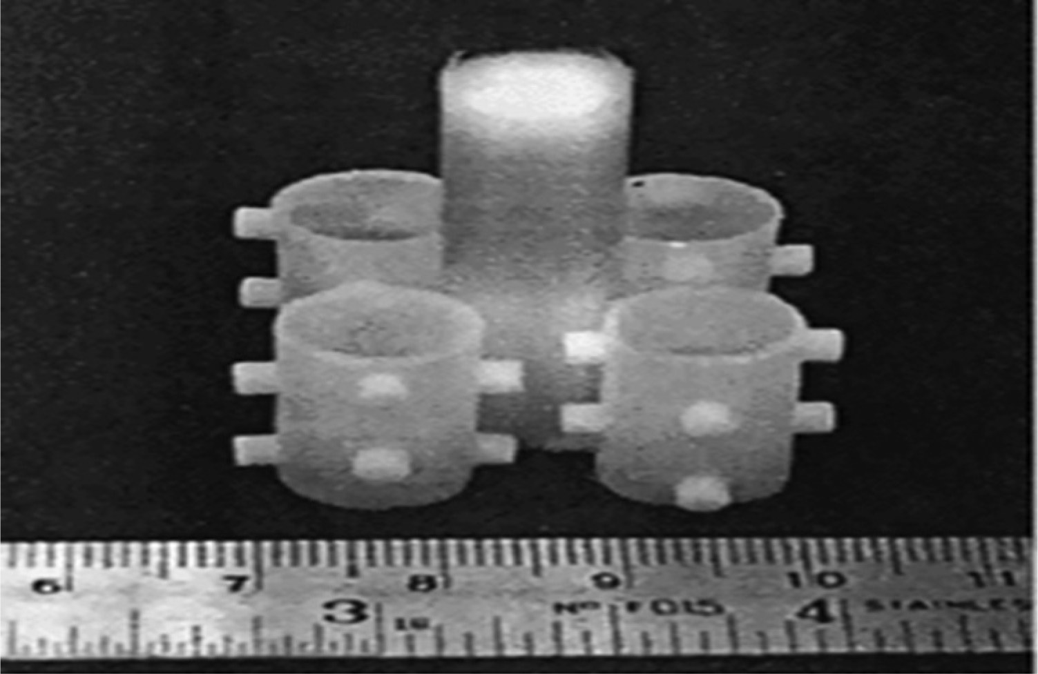
Section of the stent tree. 96
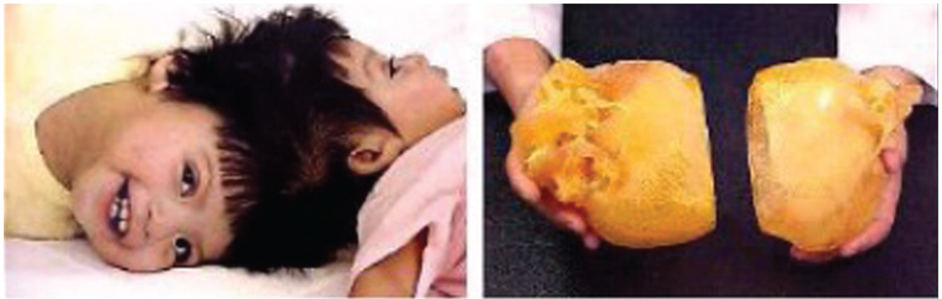
RP modelling for surgical planning to separate Siamese twin. 100
STL file of an accidental skull.
Lee et al. discussed the importance of SLS of porous scaffold for bone tissue engineering, and similarly, SLA, SLS and solid ground curing (SGC) techniques were used to produce master pattern and comparison was made between three techniques in terms of surface finish, minimum stent wall, geometrical reproducibility and fabrication time. SLS was found to be the most suitable RP process for producing tracheobronchial stents as illustrated in Table 12. 104
Comparative studies on RP process. 104
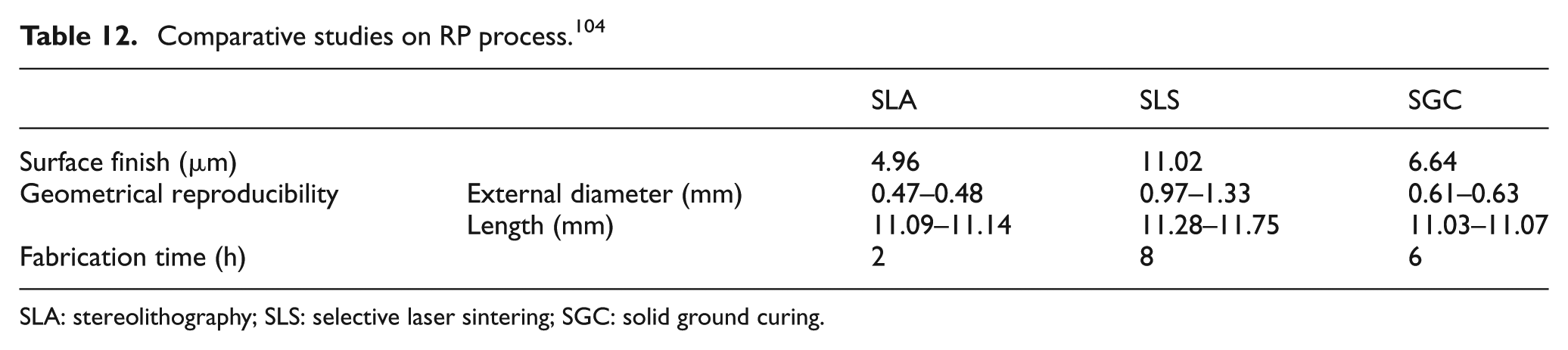
SLA: stereolithography; SLS: selective laser sintering; SGC: solid ground curing.
Many researchers outlined the application of RP in cranio-maxilofacial surgery procedure for patients having craniofacial skeleton either congenital, orthognathic deformities or accidental cause using Ti64 extra low interstitial (ELI) implant.105–109 Entire skull was mirrored using Boolean operation of subtracting original skull from mirrored and best fit was registered (shown in Figure 27). The missed section of skull made on 3D printer was tested for its dimensional accuracy (see Figure 28). Similarly, some of the researchers mentioned that titanium and SS after surface coating with oxide film were of crucial importance for biocompatibility and successful osseointegration when tested by Auger electron spectroscopy (AES) and atomic force microscopy (AFM).110–114 AFM roughness measurements on blue colour coated titanium over areas of 10 × 10 µm2 give Ra values of 68.6 nm, with maximum Z-range of 400 nm, respectively. Higher roughness compared to polished AISI 316L samples can be explained with implantation of molecules on coating when implant was in contact with bodily fluids. 3D topography of wavy surface of blue coloured implanted sample is depicted in Figure 29.
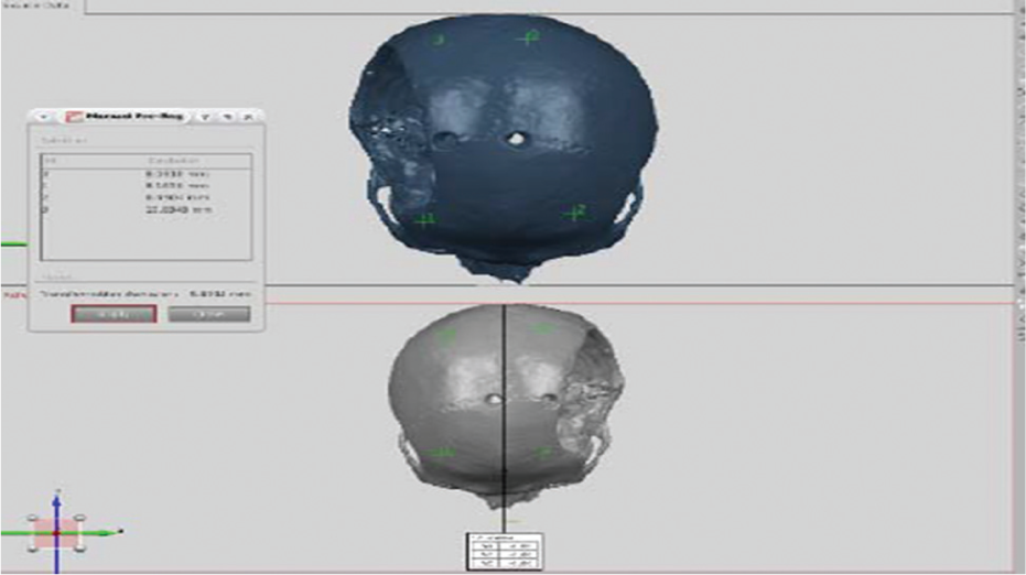
Best-fit registration of original and mirrored skull. 109
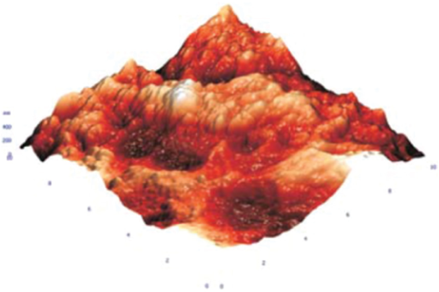
AFM 3D topography of used blue coated titanium trauma plate ‘10 × 10 µm2’. 110
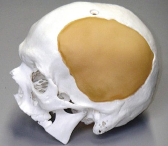
Model of skull and implant. 109
A titanium denture base plate has been designed and fabricated using a rapid manufacturing (RM) method called laser rapid forming (LSR). 115 Till date, the traditional lost-wax casting technique remains the most common technique used in dental prosthetic manufacture. The method uses a combination of reverse engineering and RPT manufacturing technologies. An impression of the maxillary edentulous was scanned using laser scanning to acquire point cloud data, and subsequently, the point cloud data were processed and a 3D model was reconstructed and converted to a STL file (Figure 30).
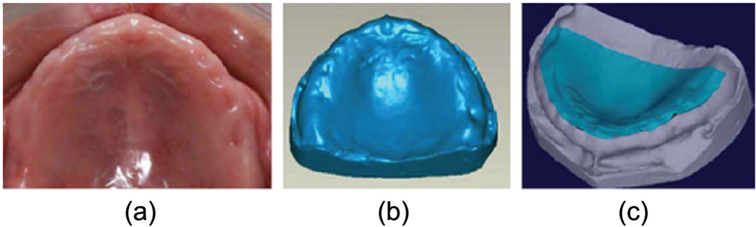
(a) Unrestored maxillary edentulous, (b) plaster 3D model and (c) denture base plate 3D model. 115
A case study involving a new replication technique was carried out for biomedical component having real 3D shape of hip joint (as shown in Figure 31). The hip joint was made using ABS material by FDM technique and mould was made by the deposition of primary, secondary and tertiary coatings with the addition of (1–2 cm in length) nylon fibre of 1.5D as per the Taguchi L9 OA control log of experimentation. Effect of input parameters such as number of layer, material of pattern and nylon addition in slurry on mechanical properties such as micro-hardness, surface roughness and dimensional accuracy was studied. It was found that addition of nylon fibre dramatically increases the fired permeability at casting temperatures. 55
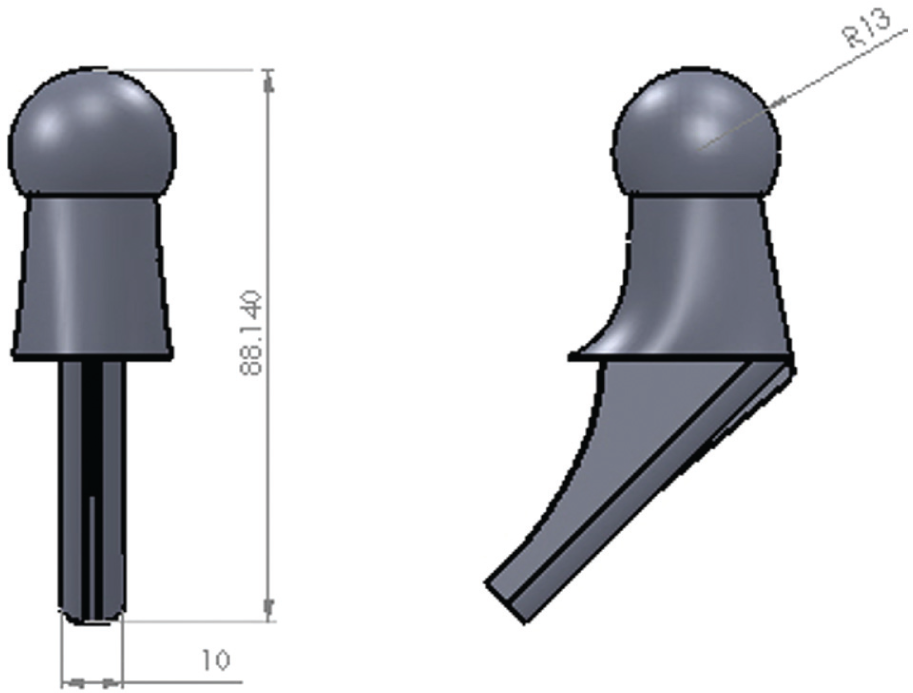
3D view of hip joint. 55
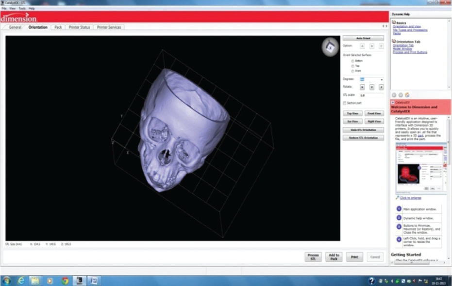
To solve the problem of a possible geometric mismatch of a selected implant, the patient-specific implant design system has been developed to help surgeons to create custom implant based upon the highly variable anatomy of the individual proximal femur for long-term fixation. Pre-existing CAD solid geometry was converted into slices (refer Figure 32) using CatalystEX. 116
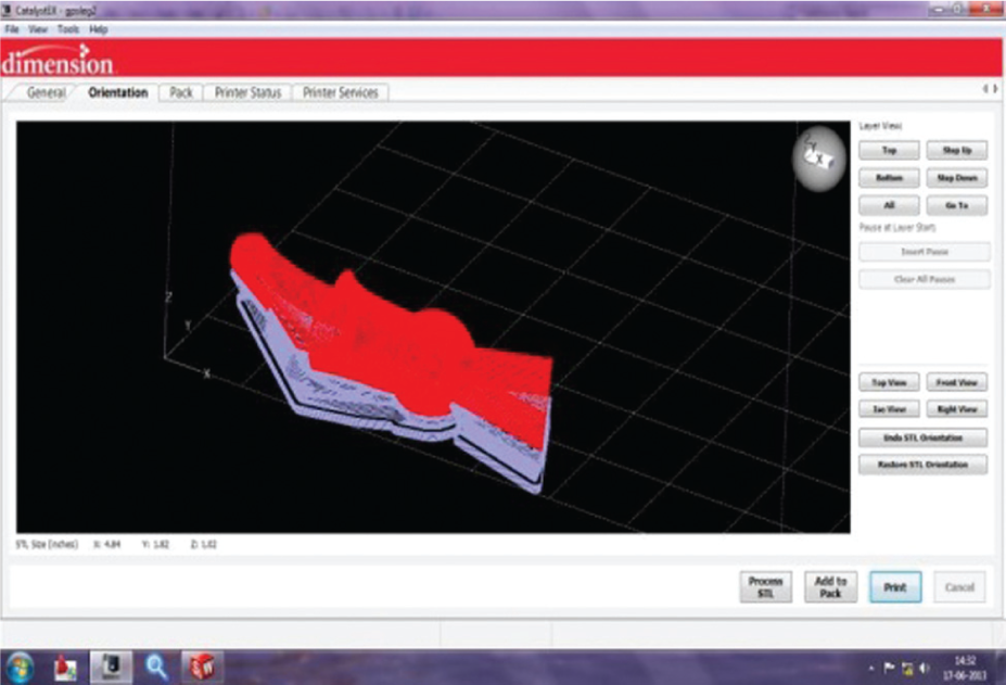
Slicing of hip joint. 116
There is a good possibility that any organ, no matter how complex, may be generated using RP technology. Early researches have been carried out that are quite encouraging and the nascent field of tissue engineering is moving ahead rapidly. Stem cells, bones, joints, tissues and scaffolds can be created in a variety of ways using RP.
Future trends
Lot of research has been conducted on the advancement of ceramic shell using metallic and non-metallic fibre/polymer, but no research has been conducted till date considering one of the most critical factors, that is, cost of shell building. Potential of fibres such as coconut, bamboo, corn, wheat straw and yucca should not to be forgotten and must be used to develop cost-effective ceramic shell. ABS-based pattern produced by FDM process has critical limitation in terms of rough surface results when used in IC process. Many researchers tried to optimize FDM parameters to minimize its roughness but research lacked considering pre-finishing of ABS pattern, before its end use, using furnishing stations. IC process is not limited to conventional but has explored its potential when hybridized with other techniques. Many researchers have done patent-based research and suggested alternative routes of IC, RPT and development of MMCs. The applications of traditional IC process to obtain components in discontinuously particle-reinforced MMCs of aluminium using the double stir method have been studied which mixed liquid slurry of aluminium alloy, and 20% SiC or 7.5% B4C carbides obtained were tested for resistance to wear in a case study of textile industry.117,118 The volume content of B4C particles is very close to the nominal introduced; however, SiC volume is less than nominal because it sank during the mixing procedure. Production of MMC by hybridization of silicon moulding–IC and using hybrid filament of FDM for pattern making in IC has been claimed.86,119 Apart from MMC, many other applications of IC in RP and medicine are illustrated before.
The geometric requirements are at the performance limit of today’s RP systems. However, special-purpose systems could likely be built using existing technology to meet these requirements, and existing chemistry holds a lot of promise, as well. Some possibilities are offered by biodegradable polymers such as polylactic acid and the caprolactones. These materials are used at present for dissolvable sutures and their chemistry is well understood. Materials might require the development of specialized RP processes before utilized in a way that meets the geometric requirements.
Conclusion
There is no certainty of date when the first step was made in IC, but there are physical proof of late 5000 BC when IC was used for the manufacturing of various commercial and artistic items such as jewellery, idols and art castings. In early 19th century, it was used to produce complex shapes such as turbine blades, airplane parts and modern weapons. Furthermore, IC showed its capability of manufacturing intricate shapes with high accuracy, fine impressions and tight geometrical tolerance. Recently, RPTs have successfully assisted IC process in terms of product development and RC solutions. RP-assisted IC has unlimited industrial and medical applications. Based on the literature review, the following conclusions can be drawn:
Number of slurry layers is found to have significant effect on casting properties such as surface hardness, dimensional accuracy (Δd) and surface roughness (Ra). Parameters such as viscosity, bulk density, plate weight, suspensibility, gel velocity and strength were compared for different zirconia-based binders and found a surprise variation in the physical properties.
Furthermore, it has been found that addition of nylon fibre, polymer, PVA, Al-Si fibre and binder hydrolysis of varying proportion in primary slurry layer improved green and baked strength, micro-hardness, crack resistance of ceramic shell and tensile strength and decreased shrinkage, surface roughness and dimensional variations.
RPT, in the field of engineering, medicine and surgical planning, can be used to develop tailor-made implants. Precision of RP models facilitates the pre-operative planning of an optimal surgical approach and enables selection of correct or appropriate implants. RP in collaboration with IC is not limited to its industrial applications but it explored more in medicine engineering and MMC. In the United Kingdom, RPT has been used to help implant treatment in more than 20 patients; however, the cost of the modelling process is currently a major limitation to its use.
Research on fabrication of small- and thin-walled parts has to be carried out; fabrication of dental implants and restoration are the challenges not undertaken yet.
There is wide scope for RP technology in foundries, but the use of RP technique in small-average scale manufacturing industry is below average and low-cost rapid techniques are required for such industries so that conventional manufacturing practice could be replaced.
Footnotes
Declaration of conflicting interests
The author(s) declared no potential conflicts of interest with respect to the research, authorship and/or publication of this article.
Funding
The author(s) received no financial support for the research, authorship and/or publication of this article.