
Abstract
Friction stir processing is a novel material fabrication technique. This study was undertaken in order to investigate a suitable set of friction stir processing parameters to form AL7075T651/TiN nano composite. A number of samples were produced by varying the process parameters, namely, tool-pin geometry, number of passes and the direction of tool rotation. The pin geometries employed include triangular, square and threaded taper; the passes were varied over two levels (i.e. 2 and 4) and the tool rotation was changed as clockwise and counter clockwise between the successive passes. The effect of these variations on the composite was quantified through several microstructural and mechanical tests. The increase in the number of passes was observed to improve various characteristics of the composite (i.e. distribution of TiN particles, grain refinement and mechanical properties). The effect of tool geometry, however, was associated with the choice of the number of passes. The change in the direction of tool rotation between the consecutive passes was witnessed to improve the distribution of TiN particles. From the X-ray diffraction analysis of the samples, the formation of several new phases was detected. These were found to have effect on the mechanical properties of the composite. A good trade-off among various properties of the composite (i.e. hardness, tensile strength and ductility) was realized when the friction stir processing was performed using square tool and employing four passes with simultaneously changing the direction of tool rotation between the successive passes. This study is the first report on the fabrication of AL7075T651/TiN nano composite through friction stir processing route.
Introduction
Friction stir processing (FSP) is an emerging microstructure modification tool. In fact, this process has been derived from friction stir welding (FSW), 1 which is known as a solid state joining method extensively employed for the welding of non-ferrous metals in the aerospace sector.2,3 Being simple, flexible and friendly to environment, the FSP process is believed to be a sustainable and cost-effective alternative of the conventional material processing methods suffering from drawbacks of polluting emissions and high equipment and consumables costs. FSP has demonstrated superiority not only over the physical methods but also over mechanical techniques such as equal channel angular extrusion 4 and multiaxial alternative forging. 5 Because of these salient features, the process is gaining increasing popularity in the materials and manufacturing sectors. 6
FSP in the simplest form employs a non-consumable rotating tool with a specially designed pin and a shoulder as integral parts. The process starts with the plunging of pin into a monolithic workpiece. The pin travels along the defined path and breaks the material by stirring action. Concurrently, the shoulder applies pressure on the stirred material to achieve consolidation. A lot of heat is generated due to plastic deformation and friction at the tool–material interface raising the temperature and thus assisting the flow and recrystallization of the parent metal (PM). However, the temperature is low to cause the melting of material ensuring solid state processing. As a result, the material does not loose alloying elements and the workpiece does not experience severe distortions, thus securing fine microstructure and metallurgical properties. 7
FSP has found a variety of applications such as grain refinement of the materials for superplastic forming, 8 homogenization of materials, 9 rectification of the casting defects 10 and surface modification. 11 As the product material, the FSPed materials have been used to make electrical contacts, welding and electrical discharge machining (EDM) electrodes and the devices for the electronic and thermal management applications.12,13
Laser sintering (LS) and double glow plasma (DGP) are frequently used as composite fabrication processes.14,15 However, high costs involved in purchasing the equipment/consumables render them costly. Furthermore, high temperatures involved in these techniques, specifically in DGP, sometimes lead to the development of unfavorable phases damaging the parent microstructure and properties. The heating in FSP, on the other hand, is local, and thus the temperature can be controlled to overcome such difficulties. Nowadays, therefore, the researchers are doing extensive efforts to employ FSP as a cost-effective alternative method for developing composites; particular examples include Al/Al2O3,16,17 Cu/SiC 18 and AZ31/Al2O3 composites. 19
The AL7075T651 alloy is noted for high tensile and fatigue strengths. However, its applications are limited to ambient temperature because it loses strength at elevated temperatures. 20 The stability in the strength at a high temperature can be achieved through the addition of ceramic particles. 21 To the best knowledge of the authors, such a work using FSP route has not been reported for the AL7075T651 alloy. In this study, FSP is employed to mix TiN particulates into AL7075T651 alloy forming a nano composite. The parameters, namely, tool geometry, number of passes and the direction of tool rotation, are varied, and the effect of these variations on the properties of FSPed composite is examined through various microstructural and mechanical tests. As a result of these investigations, an optimum set of parameters fabricating composite with a suitable set of properties is proposed.
Experiments
The PM used in this study was the AL7075T651 alloy plate of 5 mm thickness, 120 mm length and 100 mm width. The reinforcing medium was 99.98% pure TiN powder milled to nano scale particles (30 nm). In order to mix reinforcing particles to fabricate the AL/TiN composite, a groove of 2 mm width and 1 mm depth was cut in the PM and was filled with the powder. To prevent spilling of powder during FSP, the groove was closed using a pinless tool shown in Figure 1(a).
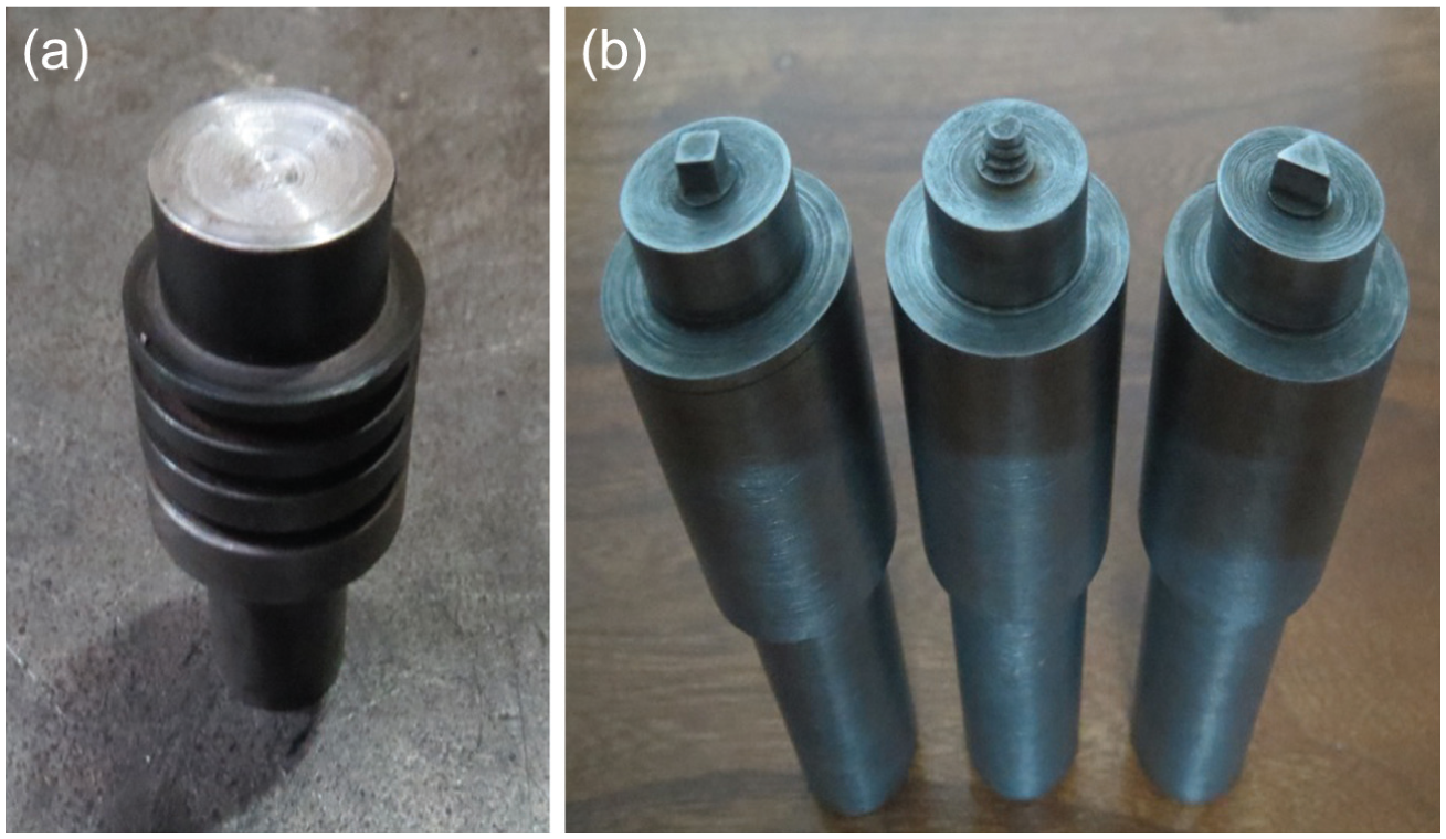
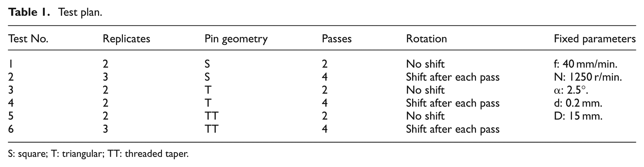
Tools employed in this study: (a) pinless tool for closing the filled groove and (b) tools with pin for performing FSP: square (S), threaded taper (TT) and triangular (T) (from left to right).
Table 1 presents the test plan. The geometry of the tool-pin was varied as square (S), triangular (T) and threaded taper (TT) as depicted in Figure 1(b). In each tool, the height of the pin was 2.5 mm, the inscribed diameter of the pin was 5 mm and the shoulder diameter was 15 mm. The tools were made from H13 steel with the hardness of 52 HRC. The number of passes was varied over two levels (i.e. 2 and 4). The direction of the tool rotation between the successive passes was alternatively changed as clockwise and counter clockwise. The pin overlap between the passes was set to 100%. The other fixed parameters, selected according to the literature,19,22–24 were as follows: shoulder penetration (d) = 0.2 mm, shoulder diameter (D) = 15 mm, rotational speed (N) = 1250 r/min, traverse feed (f) = 40 mm/min and tilt angle (α) = 2.5° (see Figure 2(a) for definitions). The experiments were performed on a conventional milling machine utilizing the setup shown in Figure 2(a). In order to provide statistical means to the results, at least two replicates were produced for each test in Table 1.
Test plan.
S: square; T: triangular; TT: threaded taper.
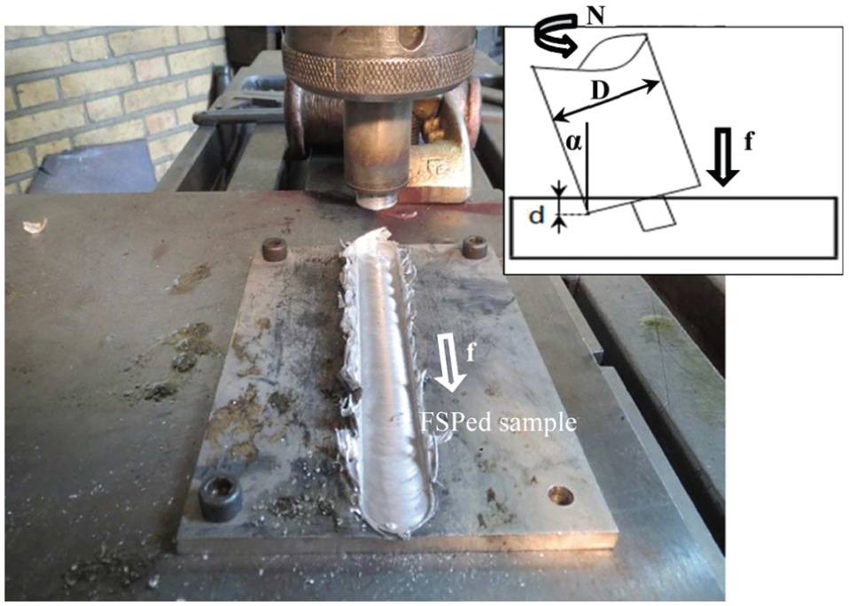
Experimental setup: inset illustrates the terminology and the orientation of the tool.
The characterization of the composite was carried out through mechanical and microstructural tests. The tensile properties were determined by conducting tension tests following the ASTM-E8 standard. However, before performing test, the top surface of the FSPed samples was cleaned by removing the ripples. The sub-size tensile samples (ASTM-E8M) were cut in the FSP direction (as indicated in Figure 3) and stretched to fracture using Instron tension test machine. The microhardness was examined on the surface of the FSPed samples. To do so, the indentation tests were performed across the FSP direction employing a Vickers hardness tester and 100 N load for 15 s on the scale of HV10. For the microstructural examinations, the metallographic samples were cut from the transverse section (i.e. thickness section X–X shown in Figure 3), polished and finally etched using the Keller’s solution. The phase composition was analyzed through X-ray diffraction (XRD) tests, and the grain size and microstructure were evaluated with the optical microscope (OM) and scanning electron microscope (SEM).
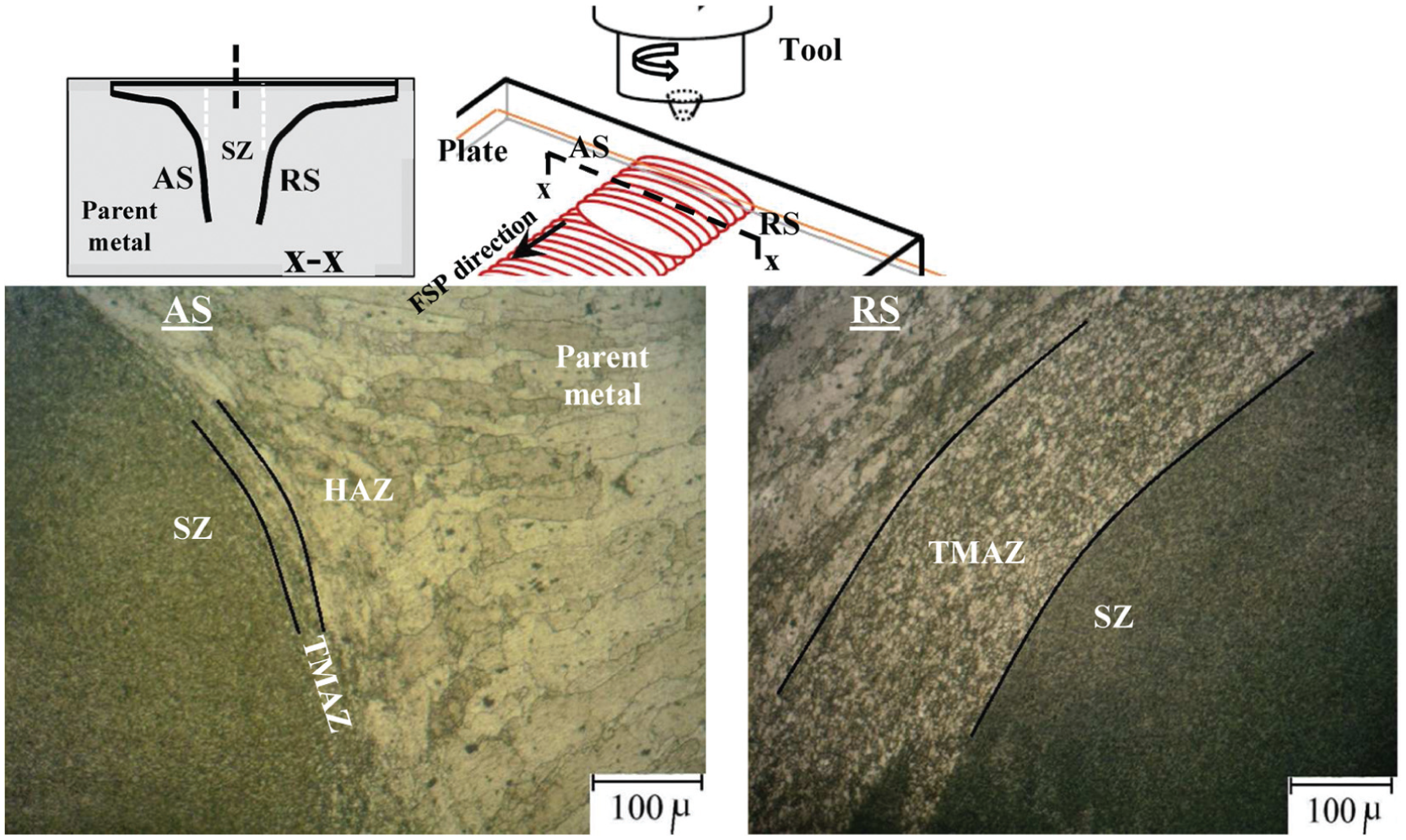
The microstructure and TMAZ band in the advancing side (AS) and retreating side (RS): microscopic tests were done on the section defined by X–X.
Results
Microstructure
Figure 3 shows the OM micrographs of a representative FSPed sample. As indicated in the figure, depending on the size and the shape of grains, three distinct regions can be identified, namely, stir zone (SZ), thermo-mechanical-affected zone (TMAZ) and heat-affected zone (HAZ). The SZ is characterized by equi-axed and fine grains formed due to thermo-mechanical action of rotating tool-pin, known as continuous dynamic recrystallization (CDRX) whereby the coarse grains of PM are broken into the fine ones through plastic deformation and friction heating. 7 The TMAZ is the transition region between the SZ and the PM identified by highly deformed grains elongated along the tool periphery. This zone is created due to plastic deformation imposed by the tool shoulder. Although the PM in the TMAZ experiences plastic deformation and high temperature, the deformation strain is not sufficient to cause recrystallization. 7 Beyond TMAZ, the PM does not endure plastic deformation but due to experiencing thermal cycles undergo property modifications. This zone is recognized HAZ.
In FSP/FSW, the metal flows from the advancing side (AS) to the retreating side (RS) of the rotating tool. The researchers are agreed that larger strain values7,25 are obtained in the AS than in the RS, thus the CDRX phenomena are enhanced in the AS reducing the extension of the TMAZ in comparison to that in the RS. As shown for representative samples in Figure 3, the TMAZ in the RS (about 280 μm) was significantly wider than that in the AS (35 μm) thus showing agreement with the previous ones. However, this difference between the widths of the TMAZ on the two sides of the SZ was observed to be comparatively low attributing to a reason that the direction of metal flow was alternatively changed between the left side and the right side of the tool.
Figure 4 depicts the SEM micrograph of an FSPed sample. The distribution of particles can be seen in this micrograph. The energy-dispersive spectrum (EDS) analysis of the particles, say A, reveals that these were TiN particulates. From the particle–matrix interface shown as an inset, it can be observed that the TiN particle is well adhered to the AL matrix suggesting that the bond between the particle and the matrix was reasonably strong. 24 These microscopic observations confirm the fabrication of AL/TiN composite through FSP route.
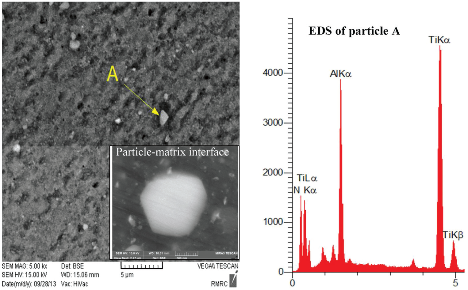
The SEM and EDS analyses of composite.
The typical SZ, also called nugget zone, of the AL/TiN composite is shown in Figure 5(a). The SZ mainly contains two types of regions, namely, dark region and bright region. Dark regions appear due to low density of TiN particles whereas the bright regions appear because of high density of TiN particles. This fact has been more clearly shown in the OM micrographs in Figure 5(b) and (c) where a dark region, contrary to SEM micrograph, represents high density of particles. To further assist reader to understand the characterization methodology employed for the SZ, some sub-regions have been marked in the SZ and their interpretation is shown through OM micrographs. For example, the pattern of zone d indicates that the particles during FSP were accumulated due to poor metal flow in that specific area. The following sub-sections provide further details on the microstructure of the FSPed specimens fabricated in this study.
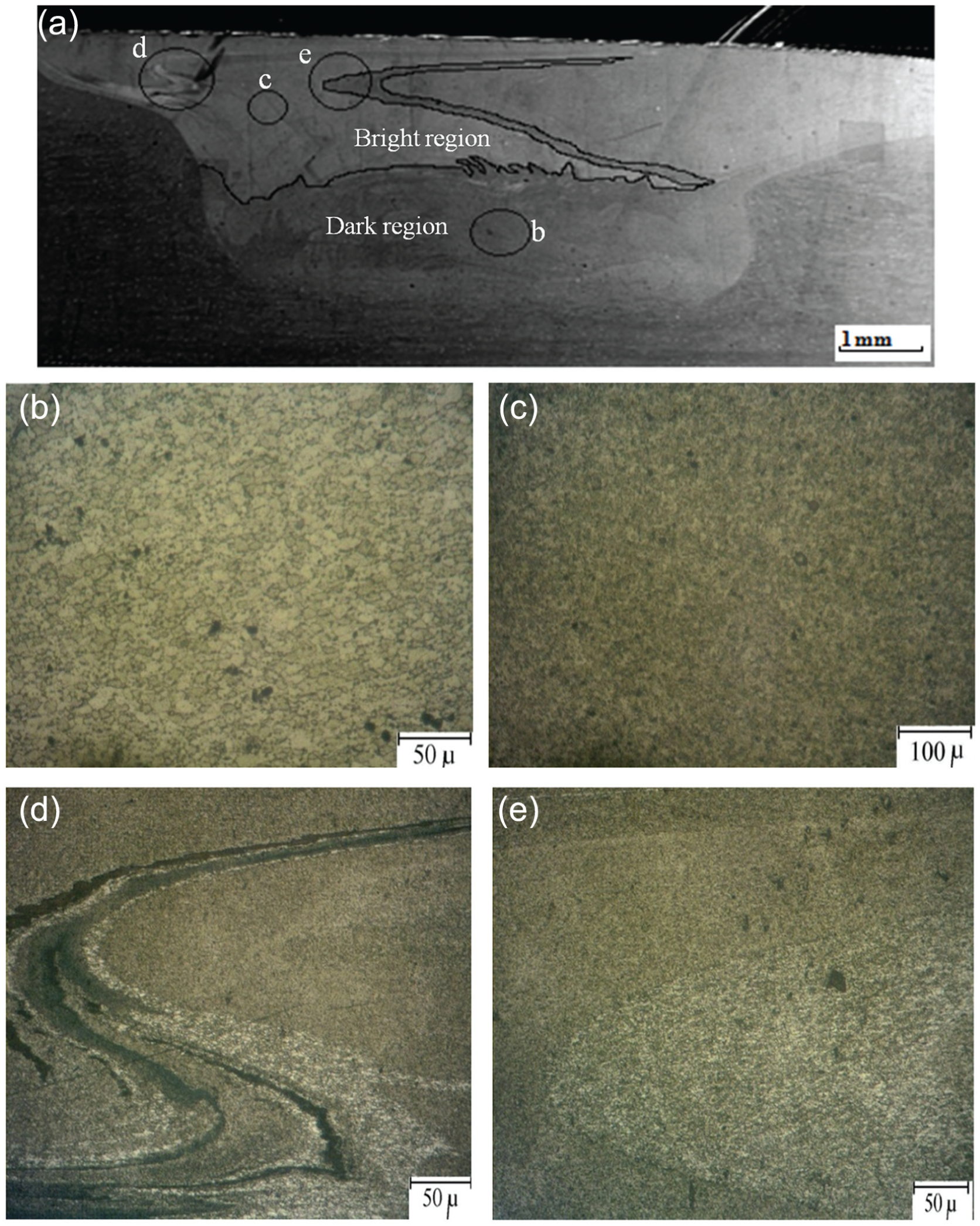
The bright and dark regions in the SZ of a sample processed with S-tool and four passes: (a) SEM micrograph and (b)–(e) OM micrographs. A bright region in the SEM graph indicates high density of TiN particles, whereas a bright region in the OM micrograph indicates low density of TiN particles.
Effect of number of passes and pin geometry
Figure 6 presents the SZ micrographs of various composite samples. From the micrographs, it can be seen that the dark area in the TT specimens is low, while the dark area in the other specimens (i.e. T and S) is high. Furthermore, the bright region in the TT specimens, in contrast to other specimens, is spread from the top to the root of the SZ which means that the TiN particles during FSP were moved downward to the bottom of the TT-tool. From these observations, it follows that the TT-tool, comparative to other tools, performed better in terms of distributing TiN particles inside the AL matrix.
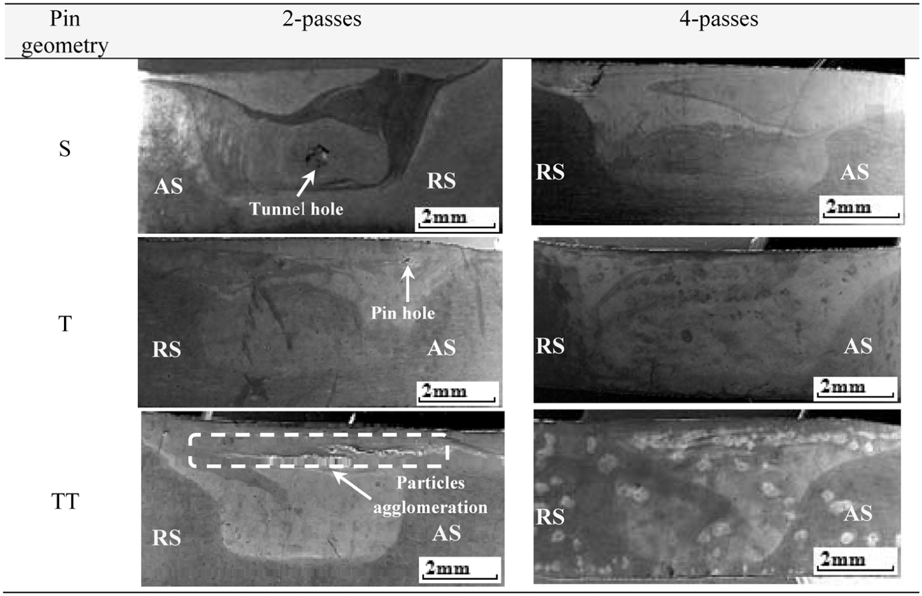
SEM micrographs showing the qualitative effect of tool-pin geometry and the number of passes on the distribution of TiN particles: bright zone is indicative of high particle density.
In the two-pass samples, the AS is comparatively brighter than the RS (see Figure 6). However, the difference in the brightness of the two sides is relatively low in the four-pass samples showing improved distribution of particles in the FSPed zones (i.e. SZ and TMAZ). In fact, the direction of tool rotation in the latter samples, contrary to the former ones, was changed between the successive passes thus altering the metal flow direction between the left side and the right side of the SZ’s center line, and as a result achieving a uniform distribution on both the sides. The defects in FSP are believed to form due to improper flow of the material.16,19 As can be seen from two-pass samples (Figure 6), the S2 and the T2 samples suffered from defects such as tunnel and pin hole; however, the TT2 sample does not suffer from any serious defect except the agglomeration of the particles. On the other hand, none of the four-pass samples suffered from any defect. These observations confirm the usefulness of the TT-tool and the significance of inter-pass change in the direction of the tool rotation to fabricate homogeneous AL/TiN composite. Azizieh et al. 19 have shown that making threads on the FSP tool facilitates metal flow and improves the distribution of reinforcing particles. This study has revealed that the distribution can be further enhanced if the rotation direction of the threaded tool is changed during the passes.
Figure 7(a)–(i) presents the mapping graphs for four-pass samples in which the distribution of Ti, N and TiN is separately shown. The highest particle density and the improved distribution can be observed corresponding to the TT4 sample (Figure 7(g), (h) and (i)) which further endorses the aforementioned good performance of the TT-tool in terms of distribution of the reinforcing particulates.
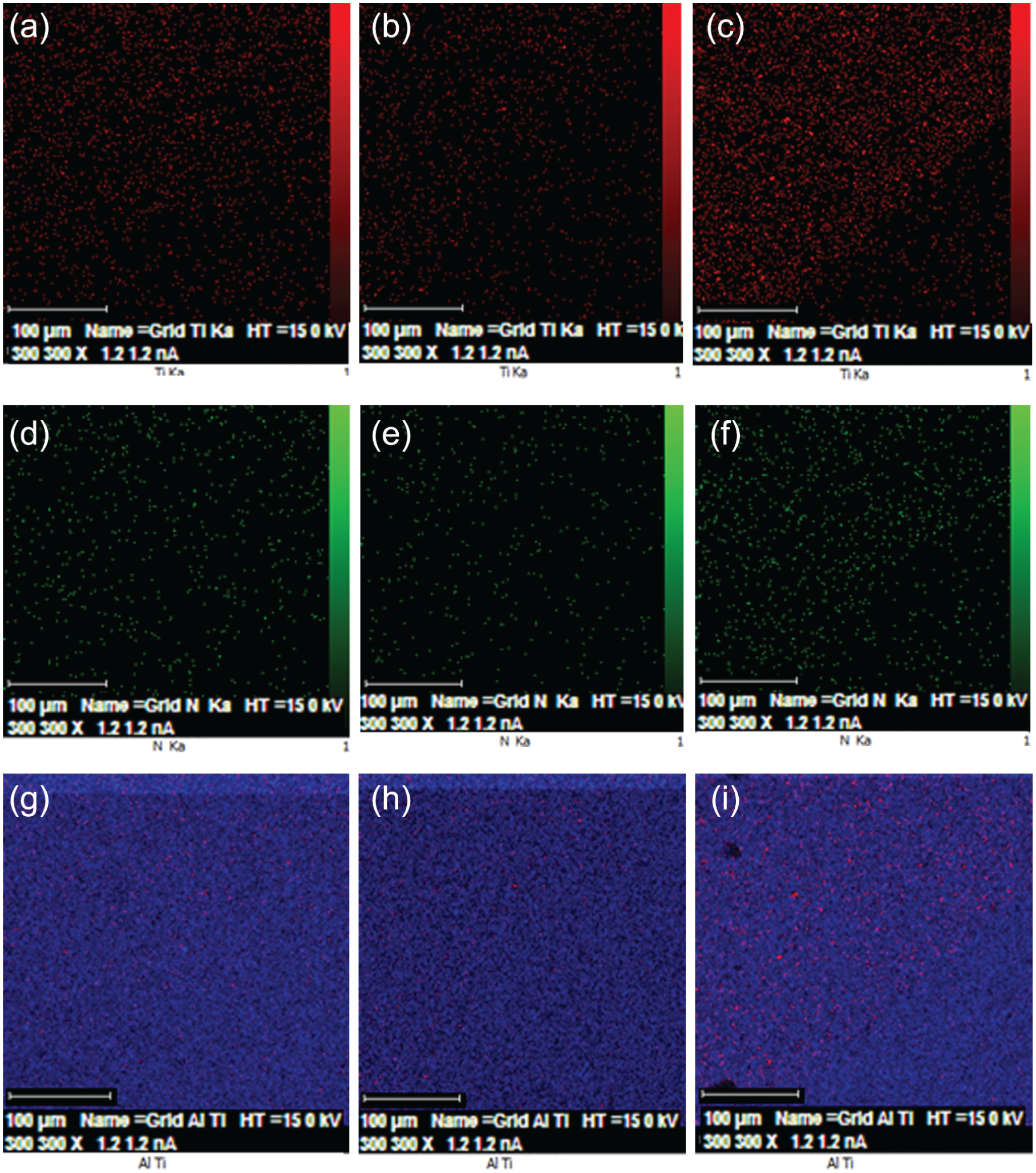
Mapping of nano powder in the advancing side of samples produced by four-pass distribution of Ti, N and TiN particles in (a–c) S-tool, (d–f) T-tool and (g–i) TT-tool.
Table 2 lists the grain size for various FSPed samples and the PM. As can be seen, the FSPed grains are substantially smaller (at least 78 times) than the PM grains. As shown in Barmouz and Givi 18 and Dadbakhsh et al. 26 and reviewed in Ma, 7 the reinforcing particles and the impurities during FSP/allied processes settle around the grain boundaries of the matrix. These particulates restrict grain boundary sliding and thus prevent the growth of recrystallized grains due to process thermal cycles, termed as pinning effect in the literature. Thus, the CDRX phenomena are enhanced in the presence of reinforcing particles. The achievement of extraordinary fine grains in the AL/TiN composite can be attributed to the CDRX phenomena and the pinning effect of TiN particles, therefore.
Mean grain size and SZ microhardness of the FSPed samples.
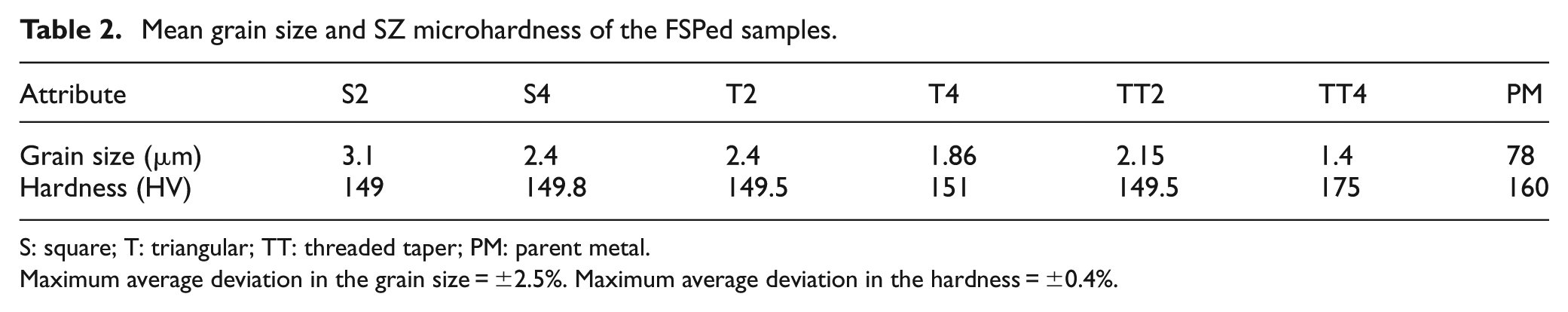
S: square; T: triangular; TT: threaded taper; PM: parent metal.
Maximum average deviation in the grain size = ±2.5%. Maximum average deviation in the hardness = ±0.4%.
The size of the FSPed grains, depending on the pin geometry and the number of passes, ranges from 1.4 to 3.1 μm (Table 2). From both classes of the samples (i.e. two-pass and four-pass), it can be observed that the TT samples have smaller grains and the S samples have larger grains. Furthermore, each of the four-pass samples is finer than the corresponding two-pass sample. For example, the grain size in the S4 sample is 2.4 μm while the grain size in the S2 sample is 3.1 μm. These findings reveal that both the pin geometry and the number of passes influence the grain size of the AL/TiN composite. This is to see that the finest grains are present in the TT4 sample, and the coarsest grains are contained by the S2 sample. This is in accordance with the distribution of TiN particles which were found to depend on the pin geometry and the number of passes. Combining the results of particles distribution presented in Figures 6 and 7 and those of grain size (Table 2), it is possible to say that the TT4 sample contains the finest grains because during FSP it might had experienced the highest pinning effect among the samples.
Phase composition
The temperature and the pattern of metal flow during FSP/FSW have been reported to depend both on the shape of the tool-pin and the process parameters.27,28 Table 3 lists the XRD phases detected in the current FSPed samples. A number of phases besides those originally present in the PM (i.e. Al, MgZn2 and Cr) can be observed. Furthermore, the type and the number of phases vary with the variation in the pin geometry and the number of passes, which according to the literature27,28 most probably can be reasoned to the corresponding temperature variations. The four-pass samples contain more number of phases than the two-pass samples do. The hard phases such as TiN (mixed in the PM) and TiC (formed as a result of FSP) are present in all the samples. The formation of several new phases indicates that TiN has good solid solubility in the matrix which may be explained by the fact that the matrix (i.e. AL7075T651) is a trivalent and highly electro-negative metal. 20
Phase composition of various FSPed samples.
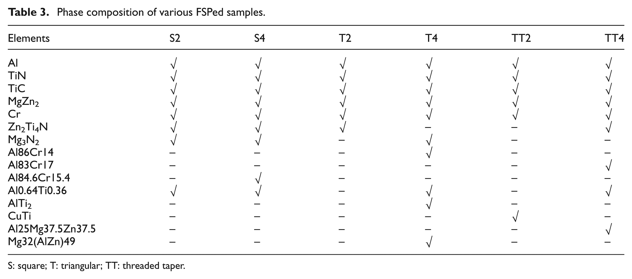
S: square; T: triangular; TT: threaded taper.
The formation of additional phases can be important with respect to having effect on the properties of the FSPed material. The AlCr phases, age-hardening compounds, are formed only in the four-pass samples. The Al25Mg37.5Zn37.5 phase, age-hardening alloy, is developed only in the TT4 sample. The CuTi, tough alloy, phase is developed only in the TT2 sample. The formation of Mg32(AlZn)49, which is present only in the T-4 sample, is of particular interest because it tends to weaken the matrix by segregating the structure at grain boundaries. Its adverse effect on the strength will be shown in the next section. This is to notice that the Al matrix in the TT4 sample is dominated by age-hardening phases, such as MgZn2, Al83Cr17 and Mg32(AlZn)49, which are prone to undergo natural aging, and thus tend to harden the matrix through precipitation hardening. Further details on the characteristics of the phases can be read in the literature. 20
Microhardness
In FSP, the hardness of the annealed materials increases as the amount of plastic deformation increases and the grain size of FSPed matrix decreases. 7 However, the precipitation-hardened alloys (such as AL7075T651 and AL6061T6) loose hardness despite receiving grain refinement during FSP. El-Rayesa and El-Danaf 23 and Pastor and Svobada 29 have shown that the second-phase precipitates, responsible for strengthening heat-treatable non-ferrous alloys, due to FSP/FSW thermal cycles experience decomposition/growth, and as a result the alloy loses hardness.
The microhardness profiles of various FSPed samples are portrayed in Figure 8. As can be seen, the hardness in the SZ of each sample is almost stable except minor variations which can be reasoned to variation in the distribution and the density of TiN particles discussed before and shown in Figures 6 and 7. This is to notice that the hardness in the surrounding of the SZ is substantially low (at least 33% relative to SZ). During performing FSW of AL7075T651 without using any cooling medium (as in this study) and reinforcing particulates, Pastor and Svobada 29 observed very severe softening behavior in the SZ in addition to its surrounding, showing that the effect of dissolution/growth of the second-phase precipitates (MgZn2) was dominant over the CDRX phenomena of the tool. As shown in Figure 8, the SZ in each of the sample demonstrates significant higher hardness (33%–40%) than the corresponding surrounding zone. This suggests that the reinforcing particles (TiN) must had played role, most likely through pinning effect defined before, in overcoming/diminishing the effect of aforesaid phenomenon related to the second-phase precipitates. Therefore, the TiN particulates can be mixed into the heat-treatable AL alloys, especially AL705T651, to control/reduce hardness loss during FSP.
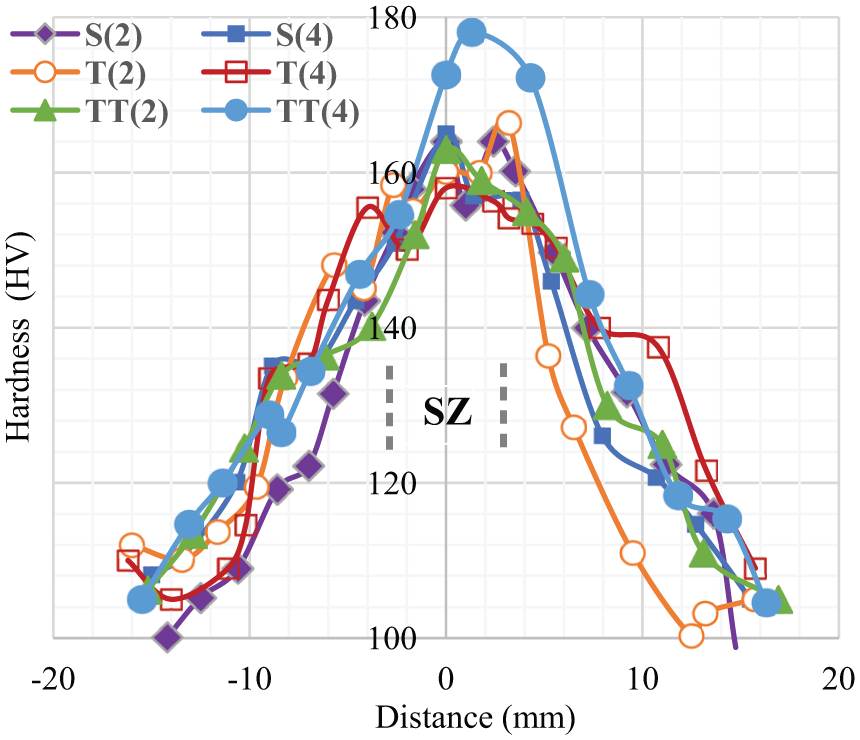
Hardness profiles for various FSPed samples.
Table 2 presents the mean hardness in the SZ of the FSPed samples. The hardness results are consistent with the grain size as the highest hardness is exhibited by the TT4 sample that contains the finest grains, and the lowest hardness is demonstrated by the S2 sample that contains the coarsest grains. This finding is in agreement with the literature,16,19,21 which reports that the hardness increases as the grain size decreases. The difference in the hardness of samples other than the TT4 sample is marginal, however. Also, the hardness of the TT4 sample is significantly higher (at least 16%) than that of other samples. This is to notice that the TT4 sample has a dominating number of age-hardening phases (i.e. Al84.6Cr15.4, Al25Mg37.5Zn37.5 and MgZn2) which are believed to improve the hardness of the material through precipitation hardening 20 ). Some hard phases such as TiC and TiN are also present in the matrix of the TT4 sample. But a careful deliberation of Table 4 and the properties of the listed various phases follow that a substantial increase in the hardness of the TT4 sample (relative to the other samples) can be due to the said age-hardening phases because the nitride- and carbide-based phases are present in all the samples Therefore, it is possible to say that besides the distribution of reinforcing particles and the grain size, the development of new phases during FSP is also an influential microstructural factor for the hardness of the FSPed materials. In the literature,16,19,21,24 it has been reported that the hardness of the particle-reinforced FSPed composites depends on the grain size and the reinforcing particles (which of course is influenced by the process parameters, e.g., tool shape and number of passes). This study reveals that the new phases formed during FSP are also important.
Comparison between the present and previous studies.
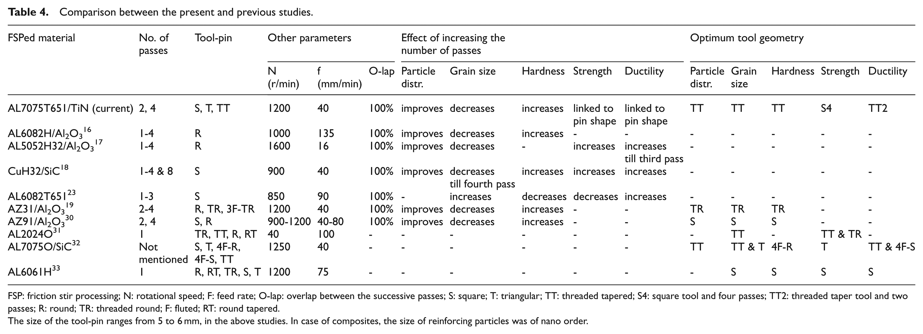
FSP: friction stir processing; N: rotational speed; F: feed rate; O-lap: overlap between the successive passes; S: square; T: triangular; TT: threaded tapered; S4: square tool and four passes; TT2: threaded taper tool and two passes; R: round; TR: threaded round; F: fluted; RT: round tapered.
The size of the tool-pin ranges from 5 to 6 mm, in the above studies. In case of composites, the size of reinforcing particles was of nano order.
Tensile strength and ductility
Figure 9(a) and (b) depicts the tensile properties of the FSPed samples. The S4 sample (grain size = 3.1 μm) exhibits the highest strength and the T4 sample (grain size = 1.86 μm) shows the least strength. Combining the results presented in Table 3 and Figures 6 and 7, no clear relation between the microstructural factors (such as grain size and distribution of TiN particles) and the strength can be established. A similar fact can be observed for the ductility. This is to notice from Table 4 that the S4 sample that offers the highest strength contains Mg3N2, a nitride believed to increase the strength and ductility of the material, 20 and two hardening phases (MgZn2 and Al84.6Cr15.4). On the other hand, the T4 sample despite containing Mg3N2 and some age-hardening phases exhibits the least strength, most probably due to containing Mg32(AlZn)49 that is believed to weaken the material through disintegration of grain boundaries. 20 The minimum ductility is achieved from the S2 sample, and the maximum ductility is obtained from the TT2 sample because it contains the CuTi phase that improves the ductility of material. 20 From these observations, it follows that the formation of new phases in addition to affecting the hardness affects the tensile properties as well.
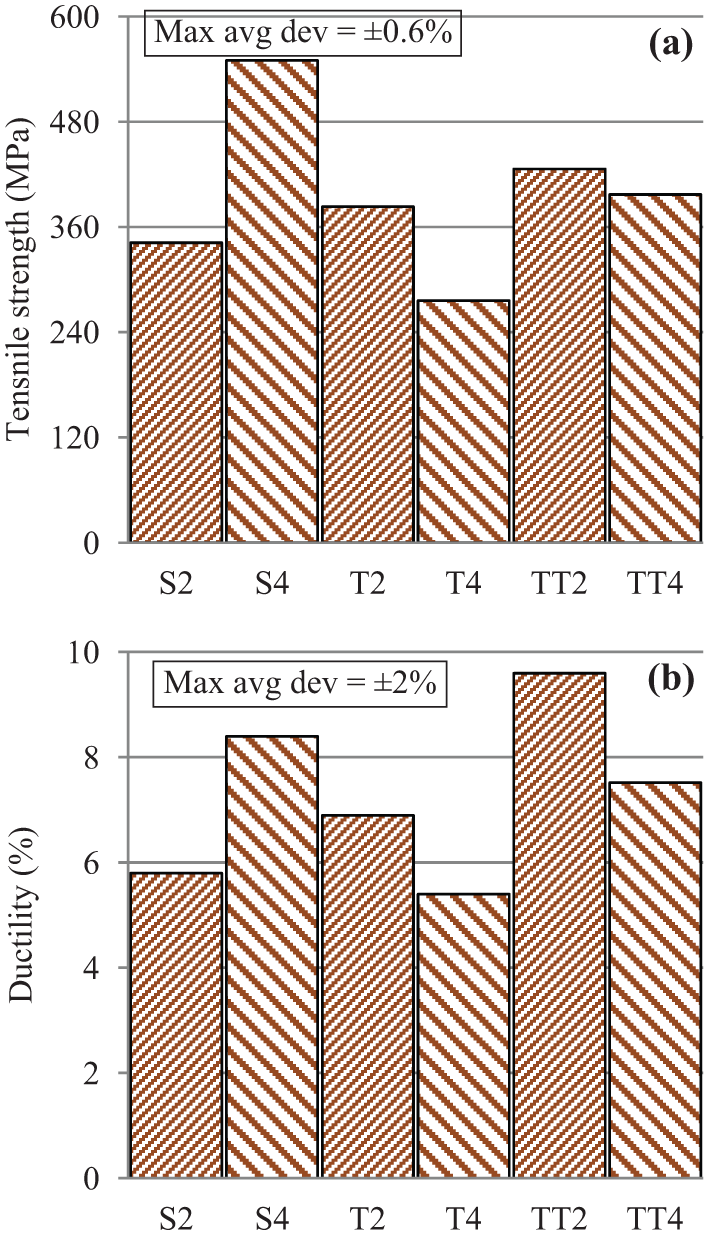
Tensile properties of the FSPed samples: (a) ultimate tensile strength and (b) ductility.
This is to see from Figure 9 that the S4 sample shows higher strength than the S2 sample does. But, on the other hand, the T2 and TT2 samples exhibit lower strength than their corresponding four-pass samples. The same fact can be noticed for the ductility. These findings suggest that the effect of passes number is closely associated with the tool shape. In other words, a tool–pass–property relationship exists in FSP.
Summarizing the results of this study, the tool-pin geometry and the number of passes both influence the fabrication of the AL/TiN composite. Increasing the number of passes, regardless of the pin shape, improves the distribution of reinforcing particulates (TiN), refines the grains and enhances the hardness of the FSPed AL/TiN composite. For tensile properties, however, the effect of passes is linked with the pin geometry employed. Moreover, no clear relationship is observed between the pin shape and the characteristics of the FSPed composite. For example, characteristics such as the distribution of the TiN particulates, grain refinement and hardness are controlled by the TT-tool. On the other hand, for tensile strength and ductility, the S-tool is the most influential tool geometry. However, overall a good trade-off among various characteristics is offered by the S-tool because it offers the highest strength and the reasonable values of hardness and ductility.
Discussion
Table 4 presents the effect of variation in the number of passes and the tool-pin geometry on various microstructural and mechanical characteristics of some non-ferrous materials FSPed in the present and previous studies. These materials can be classified as heat-treated and non-heat-treated alloys. For their strength, as mentioned earlier, the heat-treated non-ferrous alloys rely on the second-phase precipitates which are characterized by low melting point and thus on experiencing heat grow to large size (or even decompose) and tend to cause a reduction in the material strength. 20 In FSP/FSW, this phenomenon has been observed during processing of Al alloys such as in AL6061T6 and AL7075T651 alloys.23,29
With respect to the influence of the number of passes, this study and most of the previous studies16–18 listed in the table are in reasonable agreement. However, there is one study (employing a heat-treated alloy AL6061T6 as the test material) 23 that does not agree with this study, that is, the grain size coarsens and the strength and hardness contrary to the present findings decrease as the number of passes increases. This is to note that this study, as El-Rayesa and El-Danaf, 23 employed a heat-treated alloy (AL7075T651), but contrary to El-Rayesa and El-Danaf 23 additionally used reinforcing particles (i.e. TiN). Therefore, the discrepancy between the two studies is due to reinforcing particles (TiN). In fact, the material in El-Rayesa and El-Danaf 23 experienced the dissolution/growth of second-phase precipitates consequently leading to aforesaid undesired trend. However, in this study, this phenomenon of precipitates coarsening/decomposition most probably was diminished by the reinforcing particles (i.e. TiN) due to pinning effect as summarized before and explained in Barmouz and Givi, 18 Suryanarayana and Al-Aqeel 21 and Dadbakhsh et al. 26
In the literature,19,30 it has been shown that either flats or threads are necessary to produce on the tool-pin in order to achieve reasonable metal flow, grain refinement and mechanical properties. As shown in Table 4, there are a few studies which compared the performance of both types of tool geometry. Among these, Barmouz and Givi 18 and Zhao et al. 31 completely agree, and Bahrami et al. 32 partially agree (because some of the attributes follow an opposite trend) with this study. However, most of the findings in Elangovan et al. 33 significantly differ from the current ones. In fact, the metal flow in FSP depends on the tool shape and the temperature,27,28 and the temperature during processing is determined by the condition of the material (i.e. cold-worked, annealed or age-hardened) in addition to process parameters. 7 For example, recrystallization temperature is lower for pre-strained condition than that for annealed one. 20 Thus, the tool geometry and appropriate temperature determining efficient metal flow may vary from material to material and condition to condition. This explains the possible reason of discrepancies between this study and the previous studies.32,33 However, detailed experimental and finite element analyses are required to thoroughly probe this point.
In the preceding section, it was found that the effect of tool shape on the properties of the FSPed material is linked with the number of passes. Table 4 and the above discussion reveal that this effect is also associated with the matrix and the reinforcing materials employed. In generalized form, there is a tool–material–parameter correlation which is necessary to observe in order to realize a quality composite through FSP.
Future work
Tool–material–parameter relationship would be investigated for thorough understanding of the process. Moreover, the investigations will be carried out in order to know the mechanisms for the experimental findings of this study.
Conclusion
In this study, FSP was employed to fabricate the AL7075T651/TiN nano composite. With an objective to determine an optimal set of processing parameters offering a suitable combination of various mechanical properties of the composite, tool-pin geometry, number of passes and the direction of tool rotation between the successive passes were varied. The important findings of the study are summarized as follows:
The AL/TiN composite was observed to suffer from defects, such as pin hole, tunnel and agglomeration of nano particles, when processing was done without changing the direction of tool rotation between the successive passes. These defects, regardless of the pin geometry, on changing the direction of the tool rotation between the consecutive passes disappeared indicating that the inter-pass change in the rotation direction of the tool improved the metal flow during FSP.
With the increase in the number of passes, the characteristics (such as refinement of grains, particle distribution and mechanical properties) of the composite were witnessed to improve. Regarding the effect of the tool-pin geometry, a good trade-off among various attributes including grain size and mechanical properties was demonstrated by the S-tool.
The microstructural factors such as the distribution of reinforcing particulates and grain size, in agreement with the literature, were observed to influence the properties specifically the hardness of the FSPed AL/TiN composite. The highest hardness exhibited by the TT4 sample coupled with the detection of age-hardening phases (that hardens the matrix through precipitation hardening) and the lowest strength shown by the T-4 sample associated with the detection of Mg32(AlZn)49 (that weakness the matrix by segregating the grain boundaries) suggest that the formation of new phases during FSP could be another important microstructural factor affecting the properties of the FSPed composites.
Based on the above findings, it is proposed to perform FSP employing square-pin tool and four passes in order to fabricate the AL/TiN composite with an appropriate set of properties. The inter-pass shift in the direction of the tool rotation is also emphasized so as to improve the distribution of the reinforcing particulates.
Footnotes
Declaration of conflicting interests
The author(s) declared no potential conflicts of interest with respect to the research, authorship and/or publication of this article.
Funding
The author(s) disclosed receipt of the following financial support for the research, authorship, and/or publication of this article: The authors are thankful to the King Abdulaziz University for providing help and funding for this research