
Abstract
Over the last 50 years, the development of computer numerical controlled machines has seen a plethora of part programming languages being developed. The large majority of these languages are based on the ISO 6983 standard which is commonly known as G&M codes, but other languages from machine tool suppliers are also used for programming machine tools. These programming languages have provided major barriers for the interoperability of such information between computer numerical controlled machines and also from computer numerical controlled machines to computer-aided systems. Thus, the process knowledge in existing part programs cannot be recycled and reused easily, due to an inability to interpret these forms of data. In this article, a new meta-model of computer numerical controlled part programming languages has been proposed. The meta-model aims to abstract the characteristics of computer numerical controlled machine activities and interpret/represent process information within computer numerical controlled part programs written in different languages or dialects. Realising the translation between the meta-model and different part programming languages, it is possible to capture the shopfloor knowledge from computer numerical controlled machines without the need to develop individual interpreting interfaces for each programming language. The valuable process knowledge can thus be captured from the part programs and represented in a neutral presentation to facilitate the knowledge accumulation and management, which is vital for manufacturing companies to gain competitive advantages in the globalised market.
Introduction
The electronic files used to control computer numerical controlled (CNC) machines are often in a format, informally called G-codes, after Gerber Scientific Instruments, a manufacturer of photoplotters and the developer of the file format. 1 Besides G-codes, there are usually some other commands starting with M to program some other Miscellaneous functions such as coolant on/off and chip removal. Hence, this kind of part program is also referred to as G&M codes. A file containing G&M codes would comprise many lines of text that would be interpreted as moving instructions for the servomechanisms connected to various axes of the machines. 2 With the wide use of G&M codes, it became the de facto standard for CNC programming and then was formalised as RS-274D (USA), ISO6983 (ISO) and DIN66025 (Europe). 3
Compared with the first generation of numerical controlled (NC) machine, the modern CNC machines have got many advanced capabilities of such as multi-axis control, adaptive control, error compensation and multi-process manufacture. 4 With the versatility of CNC machines, the programming task becomes increasingly more difficult. For some precision and complex jobs, it is impractical to program at the shopfloor, which makes offline computer-aided software tools a necessity for efficient generation and verification of CNC codes. These software packages are usually called computer-aided manufacturing (CAM) systems. CAM systems together with computer-aided design (CAD) systems and computer-aided process planning (CAPP) systems make up a computer-aided system (CAx) chain. Along the chain, an information flow is formed from CAx systems to CNC machines.
With the rapid development of different machines and computer technology, CNC technology has advanced dramatically supporting those newly emerged machine functions. However, CNC controller vendors are very protective of every advance they made and employ proprietary standards for the enhancements that they introduced in their new controllers. 5 For example, CNC controller manufacturers introduced non-standard G-codes into the ISO 6983 standard to support their new features (additional axes, special caned cycles) resulting in various dialects for different machine and controller combinations. 6 Another reason why different dialects or languages are used to control the machine tool, the authors believe, is the simultaneous development of CNC machines tools around the world. People use different commands to program the same function. The standard 7 of programming CNC machines actually came many years later after the first NC machine was launched and the standard is proposed based on industrial practices.
Since different CNC machines use unique forms of part program, post-processors have been used to generate the correct part programs for various machines. CAM vendors have to make effort to provide comprehensive post-processors for each machine-controller configuration to be able to generate the correct dialect of G-codes for that specific combination. 8 As shown in Figure 1, each CAM system provides a unique post-processor for every machine-controller combination. Since there are many different CAM systems that employ proprietary data and algorithms, the demand for post-processors is huge. It should be noted that the controllers of different versions are treated as different controllers even with the same brand. GibbsCAM 9 claimed that there were more than 10,000 post-processors in their library. Due to different languages and combinations of controllers and machine designs, it is extremely difficult to reuse a part program on a different machine.
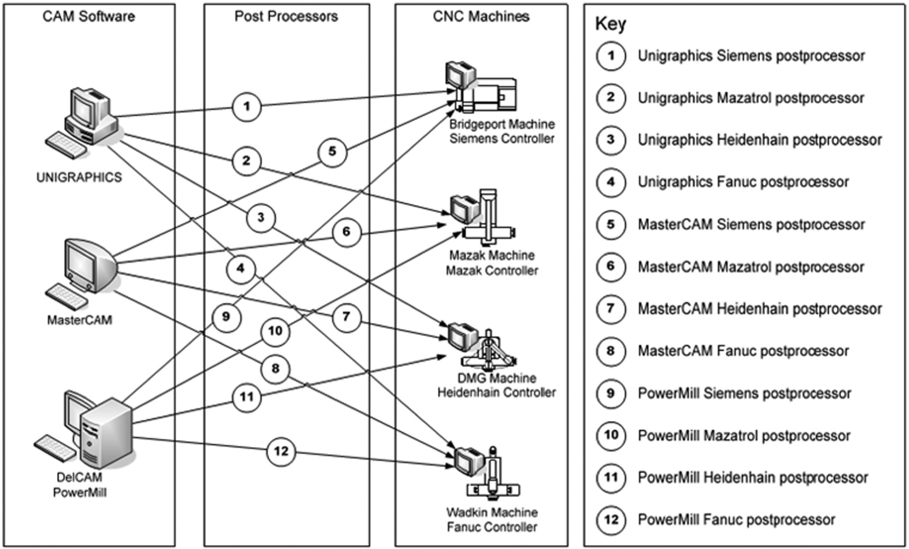
Example of post-processors for different CAM and CNC machines’ combinations.
Information interoperability between different systems is essential in the manufacturing industry. 10 The problem in terms of information interoperability in the current CAx manufacturing chain is the information island of shopfloor. The information flow from CAx to the CNC machine is unidirectional and it is not usually possible to feedback the shopfloor information up the CAx chain. The information communication with the shopfloor is an essential part for the information interoperability of manufacturing. The fact of thousands of different programming dialects has prevented it from happening, especially in a uniform and automatic way.11,12 Hence, the CNC machine is actually an information island at the end of the manufacturing chain. However, the shopfloor is an important and knowledge-intensive stage of production where valuable process knowledge or know-how is utilised by the manufacturing engineers. 13 Since the shopfloor is a complex and ever-changing environment, and the part programs are generated based on a non-real-time resource status, the shopfloor engineers are entitled to make last-minute changes to the part programs. In some cases, the process knowledge and experience are implicit and only known to very few shopfloor engineers. 12 This situation is even more common in complex aircraft components. 14 Li et al. 15 proposed the concept of dynamic feature to represent the interim features between machining operations before the final geometry is achieved, which is a new research progress in the area of feature-based technology. A dynamic feature model including changing machining effects and conditions has been developed to optimise the process plan to reduce the shopfloor modification to the part program. From this point of view, the part programs are valuable and the last, most accurate process plan is used to machine the products. This onsite knowledge buried in thousands of part programs is difficult to recycle and reuse.
Researchers3,16 have tried to translate part programs and reuse them on different machines. The disadvantage of these solutions is that they only focus on interoperability between CNC machines, not between the CNC machine and the CAx chain. Direct translation of dialectic part programs is not an effective way since there are too many different part programming languages. It works only under the assumption that the two different machines involved in exchanging part programs have the same physical axis configuration and use cutting tools with the same diameters and cutting heights. Going beyond any of these assumptions would require the toolpath and the part program to be generated again in the CAD/CAM systems. 13
In this article, a meta-model of different CNC programming languages has been proposed to represent the information and knowledge contained in CNC part programs. The characteristics of different programming languages have been analysed. An XML-based translation method has been presented. Based on the meta-model, a Universal Process Comprehension interface (UPCi) 13 has been developed to interpret the information in different part programs and represented it in a STEP-NC format. The implementation of the reverse information flow from shopfloor part programming to a STEP-NC-based process plan has been termed process comprehension by the authors. The method using the meta-model to realise the interoperability between CNC machines and other systems (CAM or CNC) has been proven to be an effective solution through the case studies.
Section ‘Introduction’ introduces the problem of knowledge loss in part programs and reviews the literature in the area. In section ‘A meta-model of CNC programming languages’, the meta-model of CNC programming languages has been proposed based on the analysis of different programming dialects. Section ‘Modelling CNC languages in XML description’ introduces the XML method to describe the programming syntax and translation method on converting programming dialects into the meta-model. The validation of the proposed approach is presented in section ‘Case studies’, where two prismatic components and two typical programming dialects were tested. Section ‘Conclusion’ draws the conclusion and highlights the contribution of this article.
A meta-model of CNC programming languages
Design considerations
In order to extract process knowledge from part programs in different programming dialects, a meta-model has been proposed in this article. The aim of the meta-model is to unify the following interpreting or translation algorithms regardless of the differences between programming dialects. As shown in Figure 2(a), without such a model, there is a need to develop separate interpreting interfaces for each type of CNC part programming dialects for different controllers (Fanuc 18i, Siemens 840D and Heidenhain iTNC 530). This work should be huge and not practical for implementation since there are thousands of programming dialects in existence.17,18 With this meta-model, different dialects can be translated and represented by this model and only one standardised interpreting interface (as shown in Figure 2(b)) is needed regardless of the type of the languages. It simplifies the task of the development of interpretation algorithms significantly. Also, the modularisation, to have separate modules of inputting and handling data, helps to make the system less complex and easy to test.
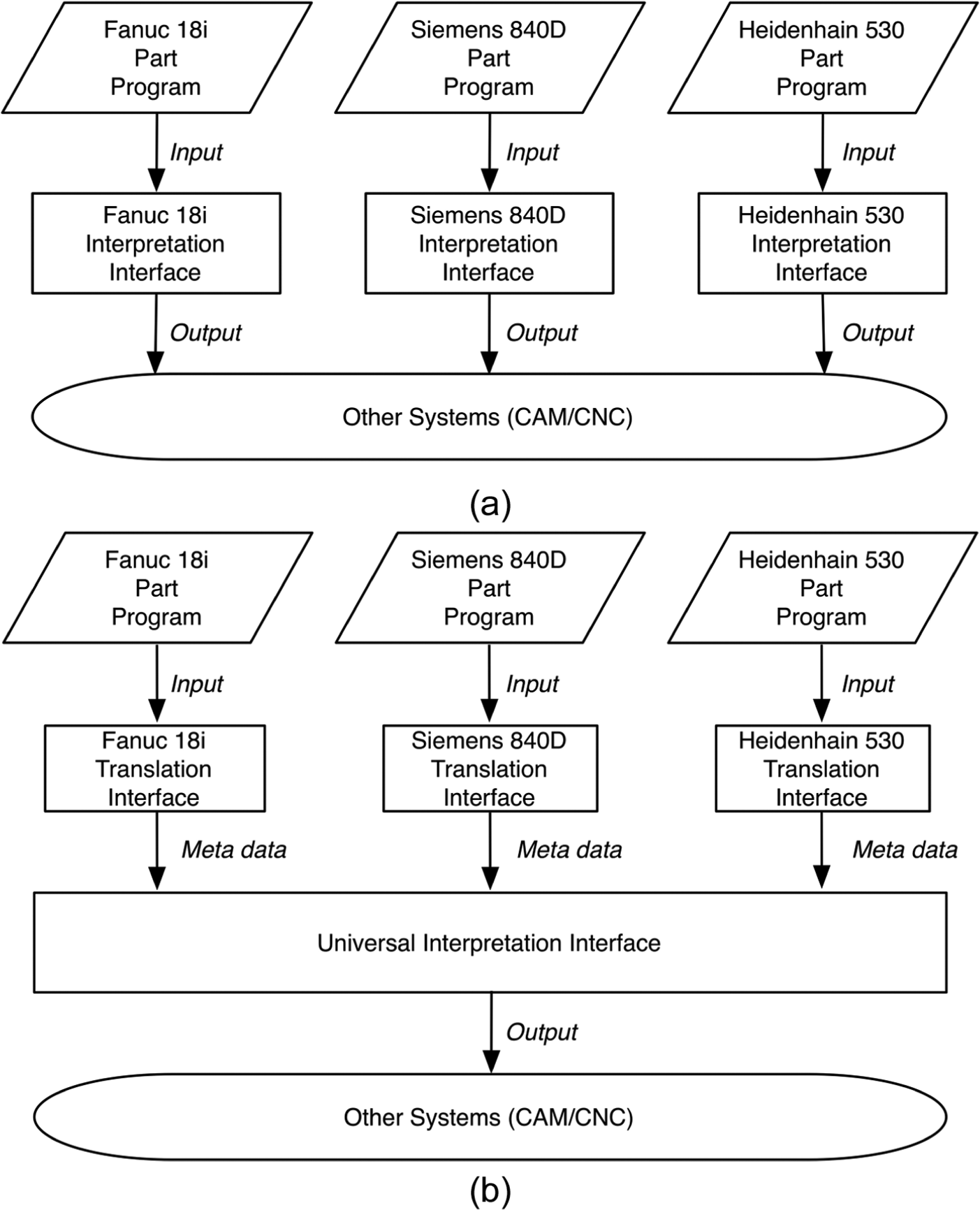
Meta-model used for universal interpretation of part programs: (a) individual interpretation for each programming dialect without the meta-model and (b) meta-model and universal interpretation interface for different programming dialects.
This meta-model has been devised with three objectives:
The meta-model should cover general functionalities of common three-axis CNC milling machine tools.
The meta-model has to be able to interpret part programs based on ISO 6983 commands and has mechanisms to incorporate other proprietary programming languages.
The meta-model should be able to represent the original process information and keep its integrity, granularity and homogeny.
To validate the feasibility to realise such a meta-model of part programming languages, comparison and analysis of the current programming dialects have been conducted.
Comparison of part programming systems on modern CNC machines
Despite the different formats of part programming languages, from the semantics point of view, they are the same in essence. They all are motion commands for physical machine tools, which can be equipped with a controller of any make. That is the reason why identical or similar machine tools, such as three-axis vertical CNC milling machines, can be controlled by either Fanuc or Siemens controllers. To machine the same component, identical machine tools equipped with different controllers perform similar or even identical motions with different part programs. Thus, the real difference between programming languages is their presentations and interpreting methods. The logic and process knowledge contained in these part programs are the same. This can be substantiated from the mechanism of the CAM system. In a CAM system, after the process planner defines the process plan, the micro-process data including toolpath and associated switching operations such as tool change and coolant on/off are calculated and generated. The next step is to choose the right post-processor to convert these data into the part program for the corresponding CNC machine, as shown in Figure 3. The process plan (cutter location data, machine functions, etc.) in the CAM system is resource independent, and theoretically can be converted into any part program provided there is a suitable post-processor available and the controller is capable to perform the task. A part program after post-processor becomes resource dependent. It is tied to a specific combination of machine tool and controller as defined in the post-processor. From this point of view, part programs are a machine-specific representation of the underlying process plan. Theoretically, it is possible to convert different part programs back to a resource-independent representation.
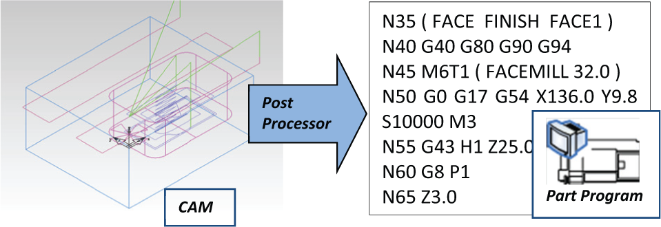
Process plan in CAM to resource-dependent part programs.
From the syntax presentation of the programming languages, it is possible to translate the part program into a neutral language. For example, in Table 1,19–21 there are several commands formatted for a Fanuc controller, a Siemens controller and a Heidenhain controller. For linear interpolation (straight cutting travel of the cutting tool from one position to another specified by the coordinates), Fanuc uses G1 and Heidenhain uses L. Similarly, for clockwise circular interpolation commands in the XY-plane, Fanuc has two types of commands format by specifying the centre of the arc and the radius. While the Siemens controller has two more command formats to identify the same arc toolpath: by specifying the opening angle or an intermediate point. Heidenhain controllers can be programmed using their proprietary language and have a special format for an arc path using command ‘CT’ without defining centre and radius, as shown in Table 1. The arc path starts from last position at a tangent with the previously programmed contour element and ends with the current position. Although they use different command formats, the semantics behind them is the same. In this comparison shown in Table 1, they are ordering the cutting tool to move along a straight line, and an arc or drilling a hole with chip breaking movements. Hence, if a neutral data model is available, different part programs can be translated into a neutral representation. In fact, there is such a neutral representation developed by National Institute of Standards and Technology (NIST) 22 called Canonical Machining Commands to represent various programming dialects. The aim of the canonical commands is to represent RS274 (US equivalent of ISO 6983) codes to realise one-to-one correspondences with commands employed by commercial motion control boards.3,23 However, this model is designed for the RS274 language dialects and it embraces more specific and low-level data. For example, a peck drilling cycle in CNC commands can be decomposed into several, possibly dozens of, canonical commands. For this research, micro-process information contained in CNC part programs is already low-level information. There is no need to interpret this low-level information into a lower and more specific level. On the contrary, it is better to keep the information granularity to help to gain a higher-level understanding of the process data at the low shopfloor level. Consequently, a new meta-model of CNC programming languages is proposed in this research to represent the process information contained in part programs written in various programming dialects.
Comparisons between Fanuc, Siemens and Heidenhain programming dialects.
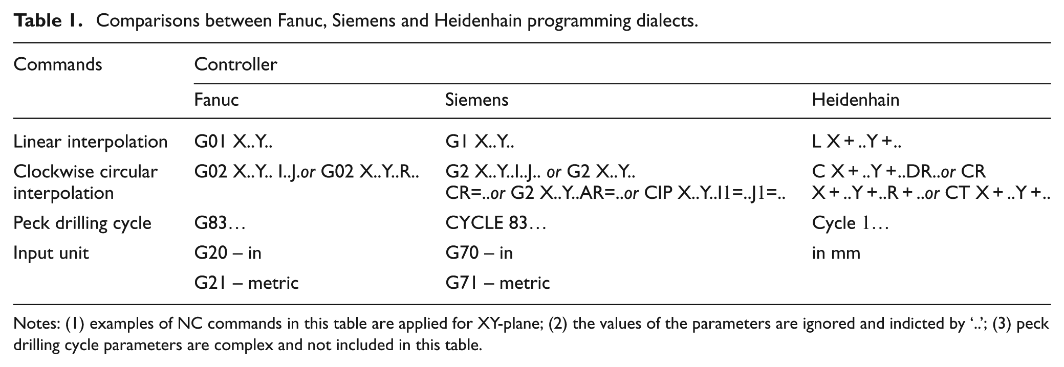
Notes: (1) examples of NC commands in this table are applied for XY-plane; (2) the values of the parameters are ignored and indicted by ‘..’; (3) peck drilling cycle parameters are complex and not included in this table.
A meta-model of CNC languages
In this research, a primary version of the meta-model has been developed. This version covers most of the commands for three-axis machining. Motion interpolations and four types of frequently used drilling cycles are included. A list of the meta-model of CNC activities is shown in Table 2.
Meta-model entities of CNC activities.
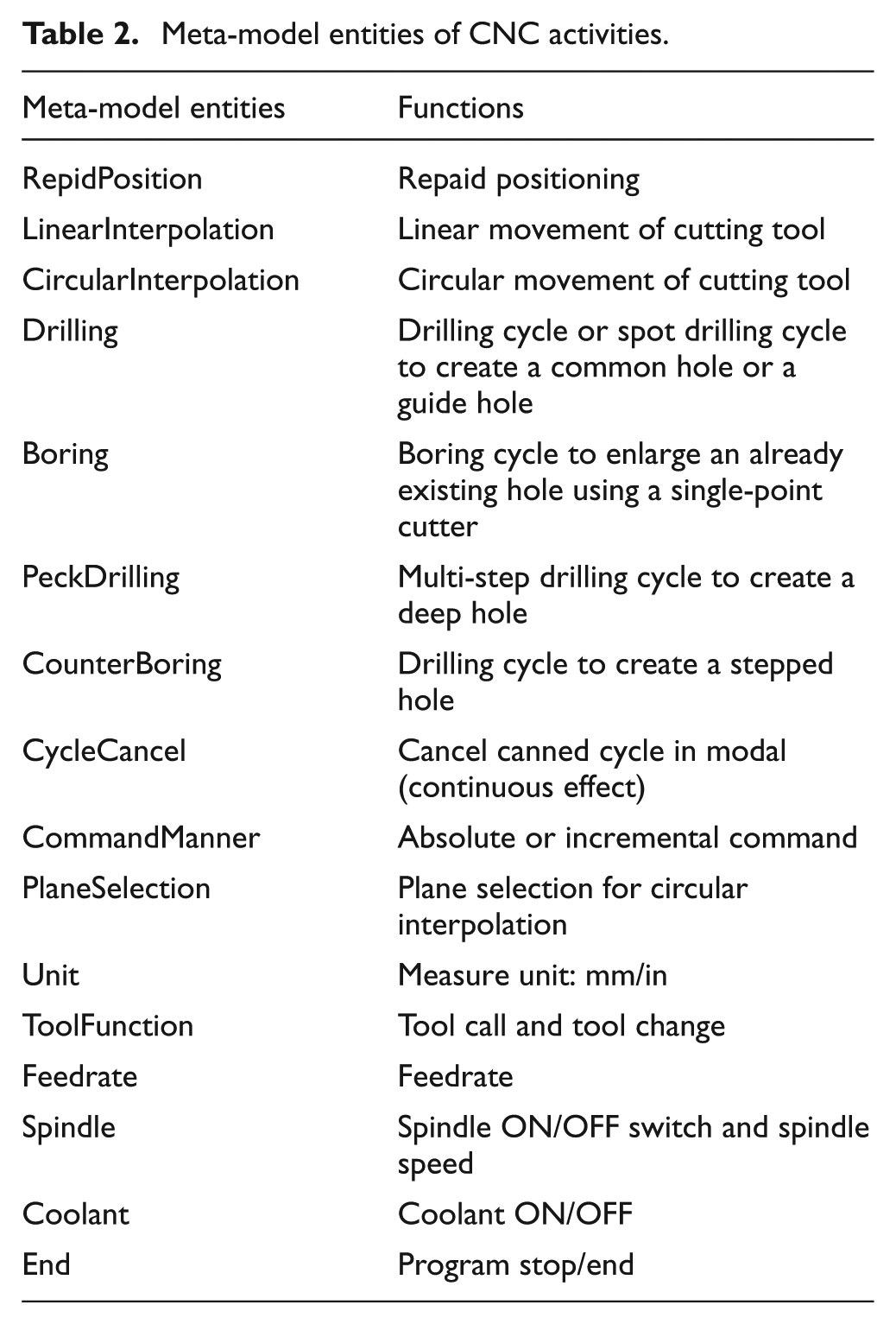
The meta-model entities listed in Table 2 are developed based on the most widely used G&M codes to meet the three objectives specified above. Although it covers most of the common G&M commands, it is not restricted to G&M codes. Judging from the names of these entities and their descriptions, it covers common movements and settings of all kinds of CNC machines regardless of what kind of controllers are equipped on them. Hence, it is possible to translate other CNC programming languages other than G&M-based dialects into this model. Consequently, it can represent the process information contained in part programs. Furthermore, it keeps and in some cases enhances the information granularity. For example, there are separate commands to specify the plane selections (or measure units) in G&M codes. In the meta-model, there is only one entity to model these choices.
Modelling CNC languages in XML description
Although the meta-model simplifies the task of interpretation significantly without the need to develop different algorithms for each CNC dialect, there is a need to develop translation interfaces between CNC dialects and the meta-model. A traditional and straightforward way to do this is developing proprietary interfaces to read in different dialects, as shown in Figure 2(b). It means there is a need to develop many of this type of interface in advance to support different dialects. In fact, it is possible to use a ‘dictionary’ mechanism to standardise these translation interfaces, as shown in Figure 4.
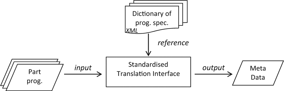
Standardised translation interface using a ‘dictionary’.
The dictionary mechanism uses a programming specification of CNC programming dialects in the form of XML to help the standardised interface to realise the translation from dialects to the meta-model. The programming specification is a description of programming format and its correspondence representation or interpretation with the meta-model. An XML method is used to describe the programming specifications. In this research, each XML file is an XML specification of a programming dialect. All the XML-based NC programming specifications assembly a dialects-meta dictionary, which works as a reference to assist the interface to translate CNC dialects into the meta-model. Each XML specification is an entry of the dictionary. Hence, it is possible to translate any CNC dialect through the interface by simply adding a new entry to the dialects-meta dictionary.
Using the dictionary method, only a single standardised translation interface is needed between CNC part program written in various dialects and the meta-model, as shown in Figure 5. Consequently, the translation interface and the meta-model can be encapsulated as a standalone system, as highlighted in Figure 5 in a dashed rectangular box. The system is titled UPCi. The part program and the XML specification of the dialect can be treated as the input of the system. This structure of the system gives it the necessary robustness and expansibility.
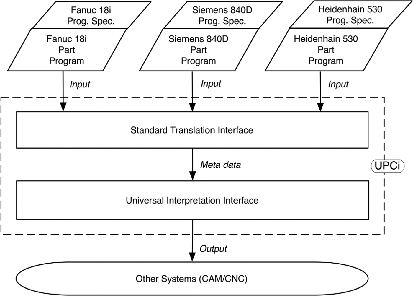
Meta-model used for Universal Process Comprehension interface (UPCi).
In Figure 6, the XML specification has been designed for the Fanuc 18i controller. In this programming specification, the programming format for the controller is defined and mapped with the meta-model. The root tag is the beginning of the XML file. The first part of the file is the file header including the detail about the specification to imply: which controller this schema is applied with, when the schema is created and by who. The second part is the basic grammar part: the basic grammar syntax about the axis words, comments and so on. The third part of the XML file is the settings of the machine tool including the spindle, coolant, feedrate and so on.
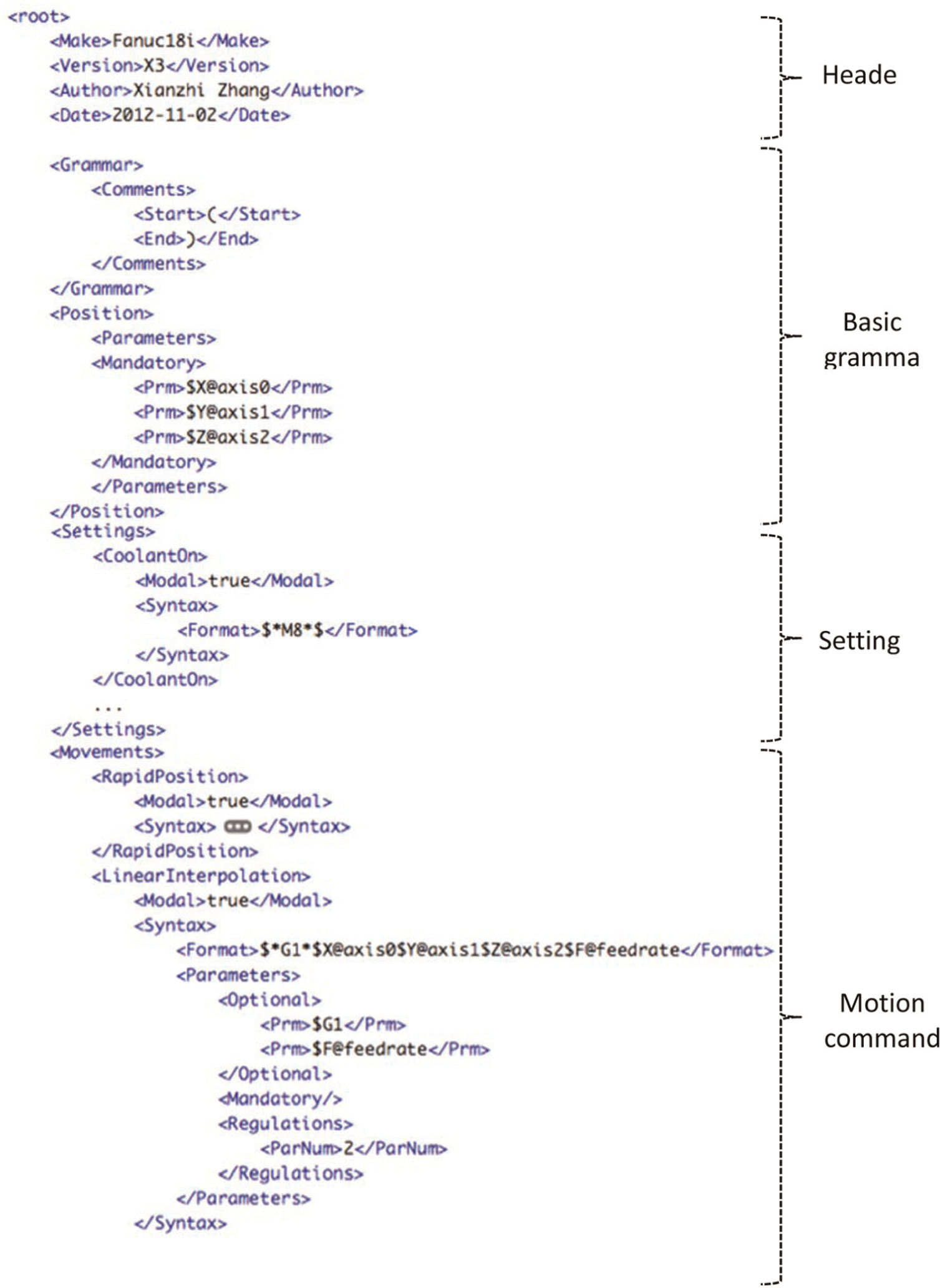
XML specification for Fanuc 18i controller.
The fourth part of the schema is about the motion commands under the Movement tag. The motion command illustrated in Figure 6 is the linear positioning of the cutting tool. The value of the Modal tag is true, which indicates this command is continually in effect without being explicitly programmed in the next command line, as shown in Figure 7. The lines N180, N185 and N190 following the line N 175 mean the same linear-interpolation command and do not need to have ‘G1’ explicitly programmed. The next tag is about the programming syntax for the command including the Format and Parameters. The Format tag defines the full presentation of the commands including all possible parameters. There can be more than one Format tag for a single command. For example, for Fanuc 18i controller, there are two format tags for clockwise circular interpolation to indicate the two options to program the cutting tool to move in along a clockwise circular arc, as shown in Table 1. The parameters of each command are defined in the Format tag and started with dollar ($) symbols. The main command word(s) is embraced by two asterisks (*) on each side. In the Parameters tag, all the parameters are listed with their functions. They are categorised into two groups: Optional and Mandatory, which indicate whether they are optional or compulsory for the command. For example in Figure 7, the position words X, Y or Z are optional for a G0 rapid position command, while Z indicates the drilling depth and R indicates the radius of the hole mandatory for the G83 drilling cycle commands.
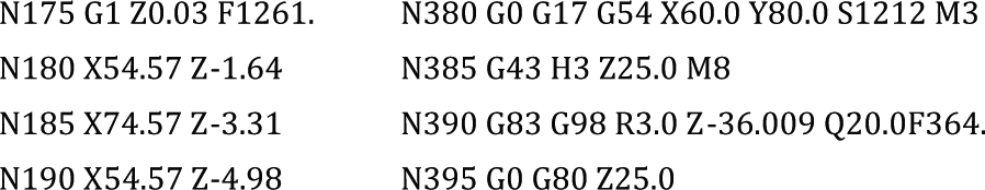
Part program segment for Fanuc 18i controller.
The mapping between the CNC dialects and the meta-model is realised with the help of NC programming specifications in the XML file. In the meta-model, for instance, there is a meta command of the linear interpolation ordering the cutting tool to cut along a straight line specified by the start and end coordinates. The Fanuc 18i uses G1 for the linear movements, which is described in the corresponding XML file, as shown in Figure 6. The translation interface of UPCi reads in the XML file and stores the description in memory. Then it reads in the part program and interprets it line by line. The detailed process to translate the part program to the meta-model is illustrated in Figure 8.
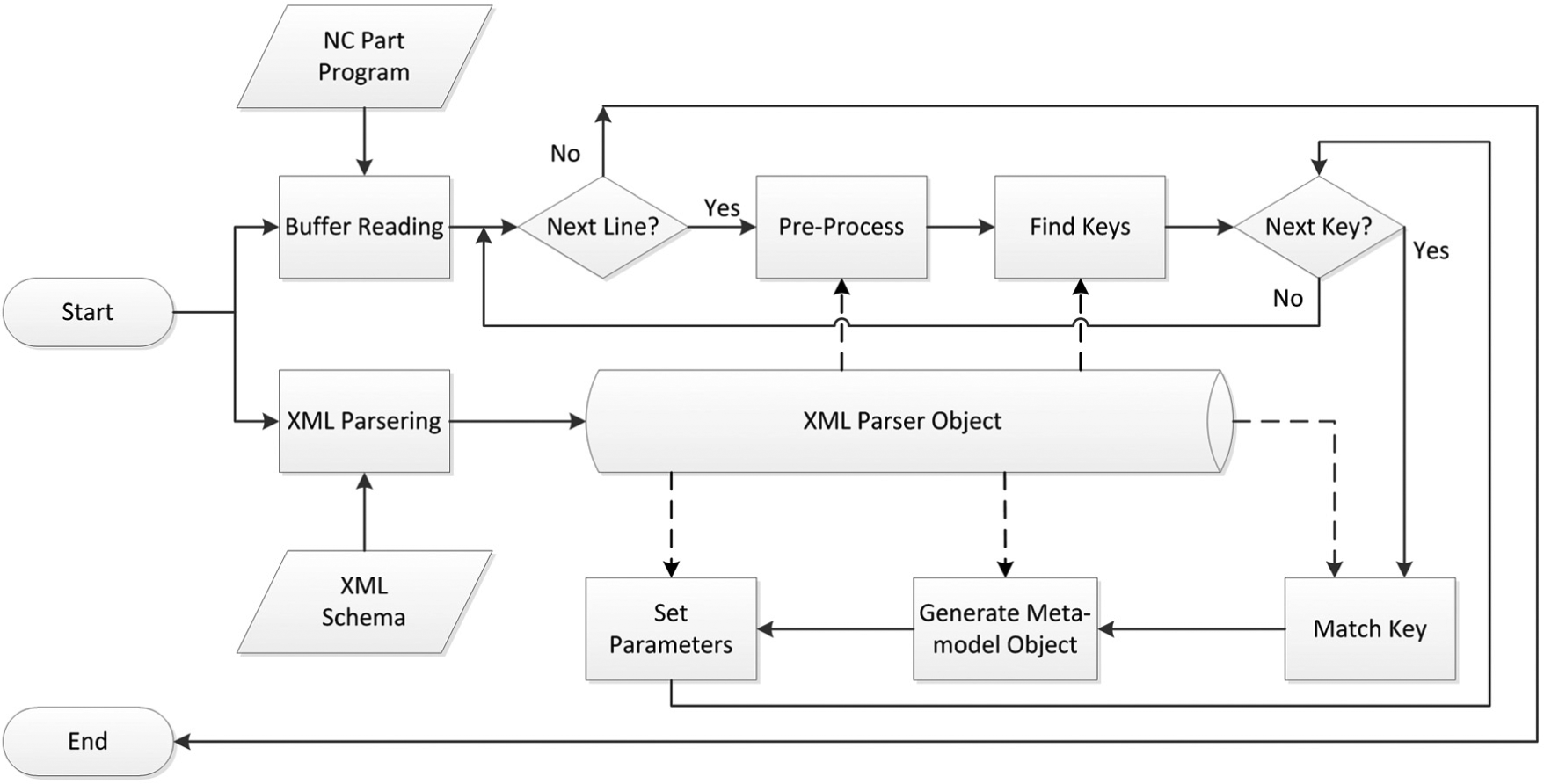
Translation of part program to meta-model.
As shown in Figure 8, the process to interpret a part program starts from loading an appropriate XML specification. In the translation interface, there is an XML parser used to parse the XML file and store it in an XML parser object. Then the part program is loaded in and handled line by line. For each line, a pre-process operation is applied to format the line into a standard presentation and get rid of the comments and so on. The XML parser object provides the necessary information regarding syntax grammar, such as comments indicators and line number words. With the standard format, the XML parser object checks the syntax of that line: how many command keys in that line? are all the mandatory keys included or not? The parser finds out the keys and puts them into a linear array. Then for each element in the array, a corresponding meta-model object is generated according to the keys listed within the XML parser object. For each meta-model object, the translation interface references the XML parser object to acknowledge the parameter words and sets values for the parameters of the meta-model object. After all the command keys translated, the same process is repeated to the next line until the whole part program is processed and the translation activity finishes. The part program is then represented by the meta-model objects, which would be used as the input for process comprehension.
The XML method used to describe the programming syntax enables UPCi to be expansible to support other programming languages. To achieve this, an XML file with the specification of the programming syntax is necessary. The users of UPCi can develop XML specifications according to their needs. In order to help the users to develop appropriate XML description files, a regulation is needed to make sure the XML files are in a uniform format to be suitable and understandable to UPCi. The regulation of XML file is used to define the legal building blocks of an XML specification of CNC programming languages.
There are many XML regulation methods available, of which the most widely used are Document Type Definition (DTD) and XML Schema or XML Schema Definition (XSD). 24 Compared with DTD, XSD is more powerful and widely used. 25 Moreover, XSD has built in data types and allows the user to custom data types, 26 which is convenient to this research. Thus, XSD has been chosen in this research to be used as the regulation method of XML specifications of CNC programming languages. The XML Schema used to regulate the XML description of CNC programming syntax has been developed as shown in Figure 9. In this schema, the basic blocks used to describe the syntax of CNC programming languages have been specified. Following the format, the user can develop XML specifications for other CNC programming languages. In implementation, the XML specifications will be checked against this schema to validate the format of the specifications.
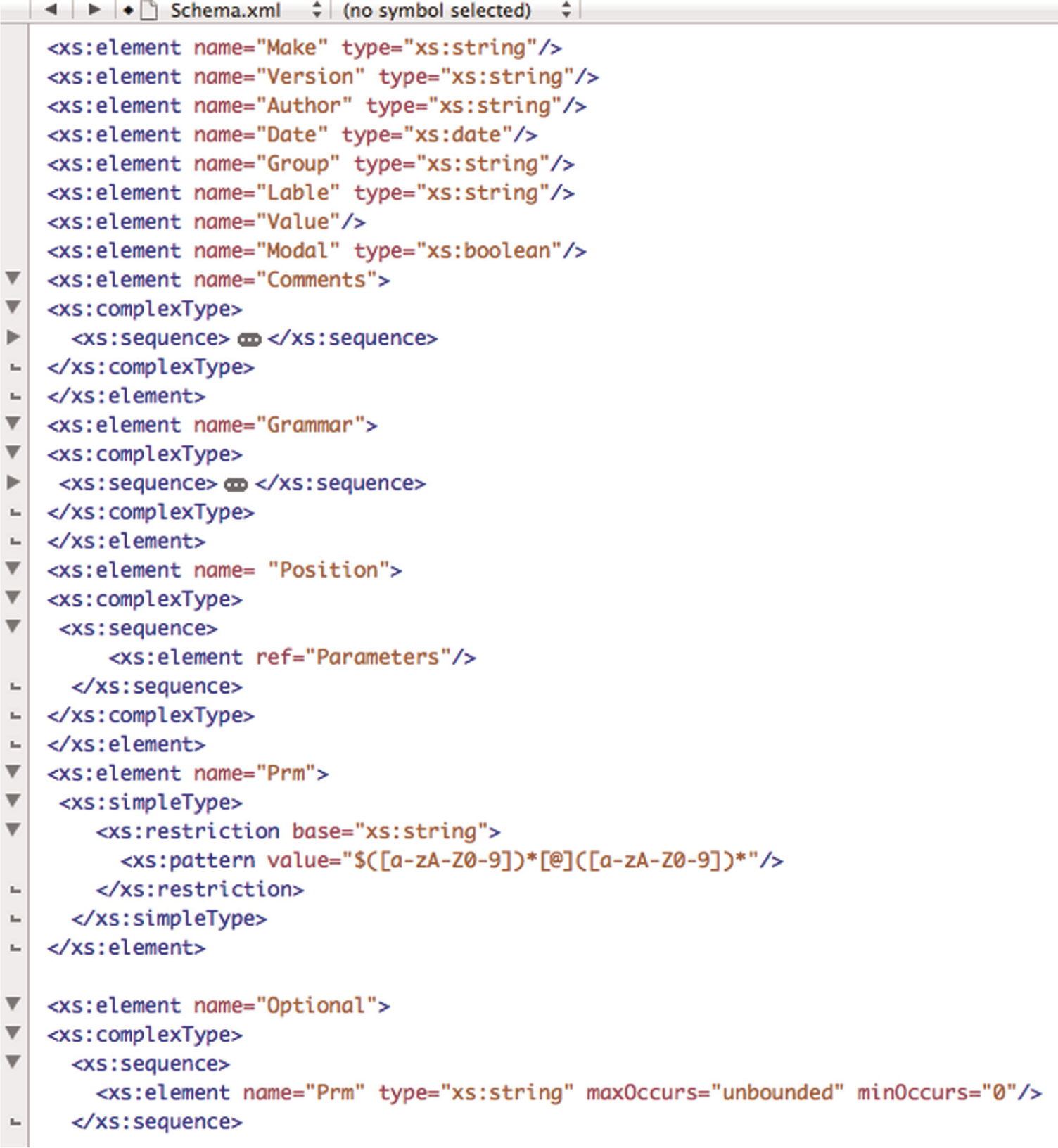
XSD file for developing of part programming specifications.
Case studies
Using the meta-model of CNC part programming languages, UPCi 13 has been developed as highlighted in Figure 5 in the rectangular box. Due to the meta-model, UPCi can work in a universal way with different part programs, which has been translated into the meta-model. UPCi is designed to capture the shopfloor knowledge and reconstruct the original process plan from low-level part programs. It is useful to realise the interoperability between CNC machines and other computer systems. The activity flowchart of UPCi is illustrated in Figure 10. There are mainly three modules: loading and translating G&M codes into meta-model data, feature recognition 27 and output generation. The output of UPCi is STEP-NC representation of process plan. The standardised format of the output enables the possibility to be used in other engineering systems.
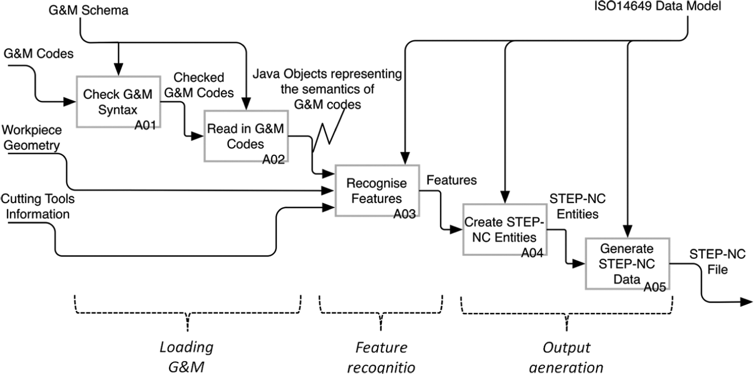
IDEF0 view of UPCi activities.
To validate the efficiency of using the meta-model to deal with different CNC part programming languages, a validation method as shown in Figure 11 has been proposed. In this method, the component is designed in a CAD/CAM system, and through two different post-processors, two copies of part programs have been generated. Post Processor 1 is for Fanuc 18i controller and Post Processor 2 is for Siemens 840D controller. Though UPCi, two STEP-NC files can be generated. To compare these two STEP-NC files, the semantics in the two file should be identical since they are all derived from the same process plan from CAD/CAM system. It is worthy to note that in each case study, a Fanuc part program has been used to machine the part, where the operator has made minor changes (starting point, tool names) to the part programs at the shopfloor.
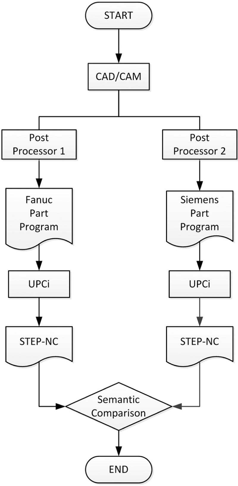
Validation method of the meta-model.
This validation method is used to prove the efficiency of the meta-model, which can be verified in two aspects: (a) accurate process plan extraction from part programs and (b) capability to translate different dialects. Hence, the validation method has been designed to cover these two aspects. The two copies of part programs generated by two post-processors are different in format, which are written in two programming dialects. However, the process plan behind the two part programs is the same. Hence, the integrity of the process plan in the STEP-NC files and the identity between two STEP-NC files will be the proof of the efficiency of the meta-model.
Two different components, as shown in Figure 12, have been used in this validation method. Figure 13 pictures the generation of STEP-NC data within UPCi. The two STEP-NC files as shown in Figures 14 and 15, generated for component 1, have been compared. From the two figures, the extracted process plan is comprehensive covering workpiece, features, operations and sequence, cutting parameters and so on. The process plans extracted from the two pieces of part programs are exactly identical except for the different tools and shopfloor changes to the Fanuc part program. The entities highlighted in dashed rectangular shows that the operations’ sequence, the planar feature and facing operation and the cutting parameters/strategies for facing are the same between two STEP-NC files. The different entities (#26, #34, #41) have been highlighted as well in solid-lined rectangular. The full results of the different entities between the two STEP-NC files are listed in Table 3.
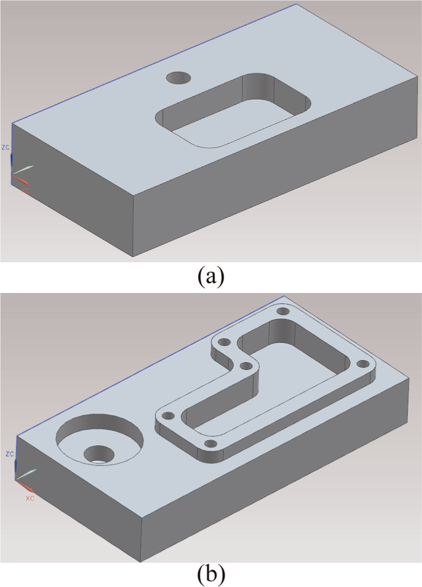
3D designs of the test components: (a) Test Component 1 and (b) Test Component 2.
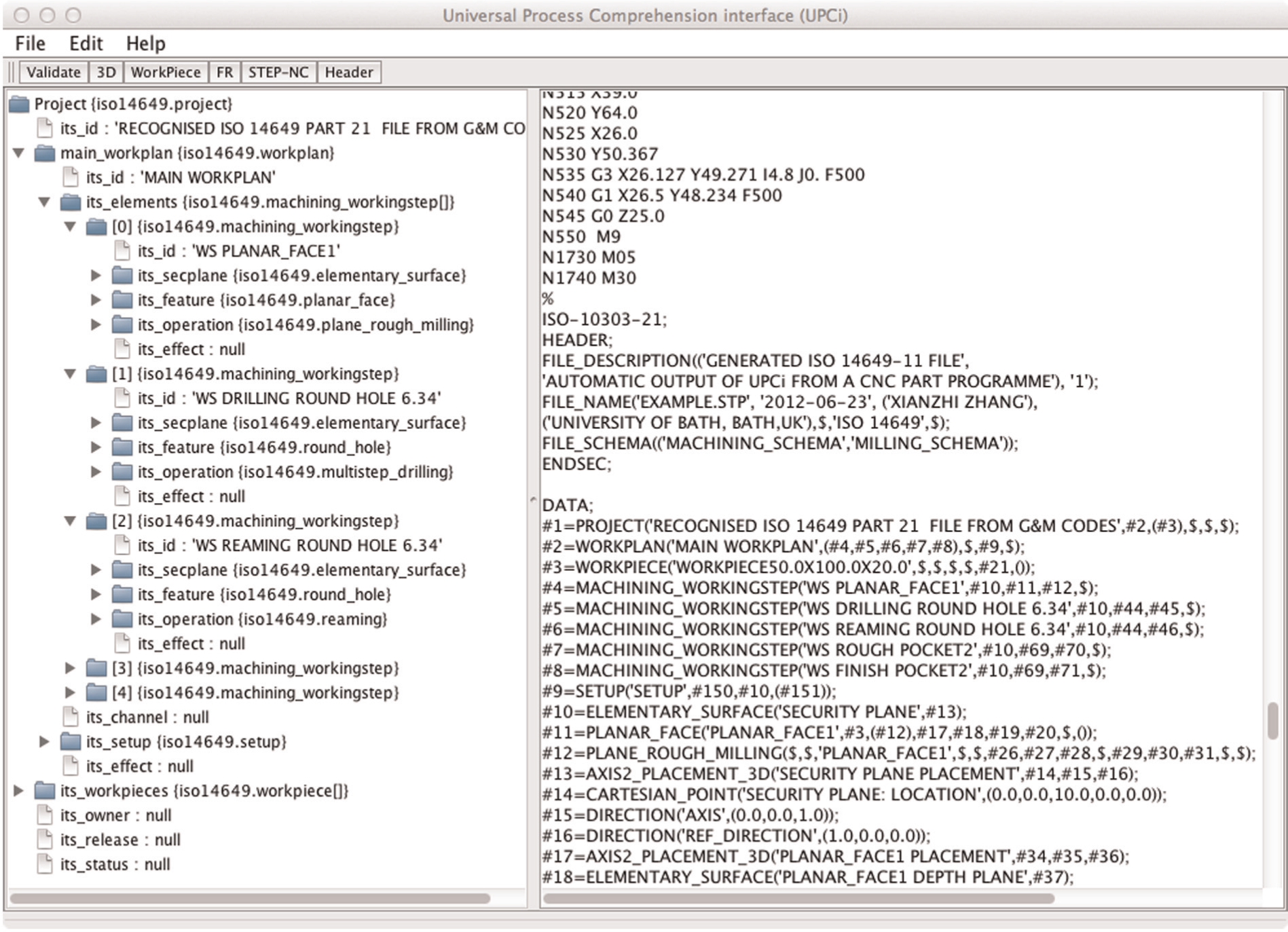
STEP-NC file generation within UPCi from Fanuc 81i part program for component 1.
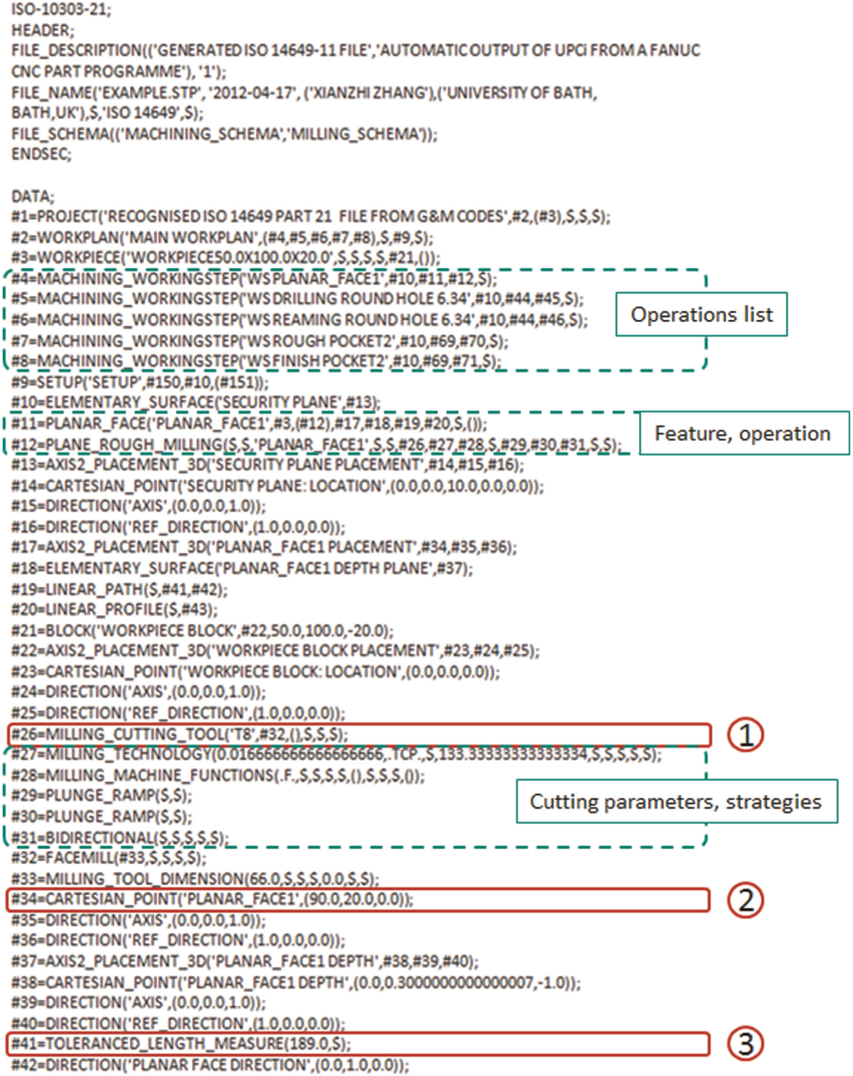
STEP-NC file from Fanuc 18i part programs for component 1.
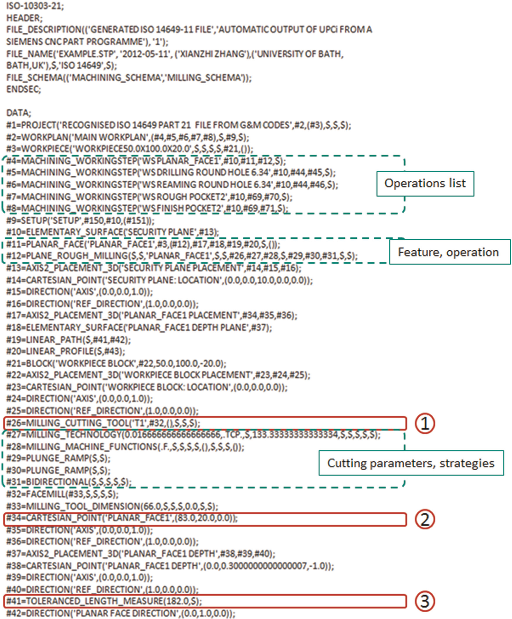
STEP-NC file from Siemens 840D part programs for component 1.
Comparison between two generated STEP-NC files for component 1.
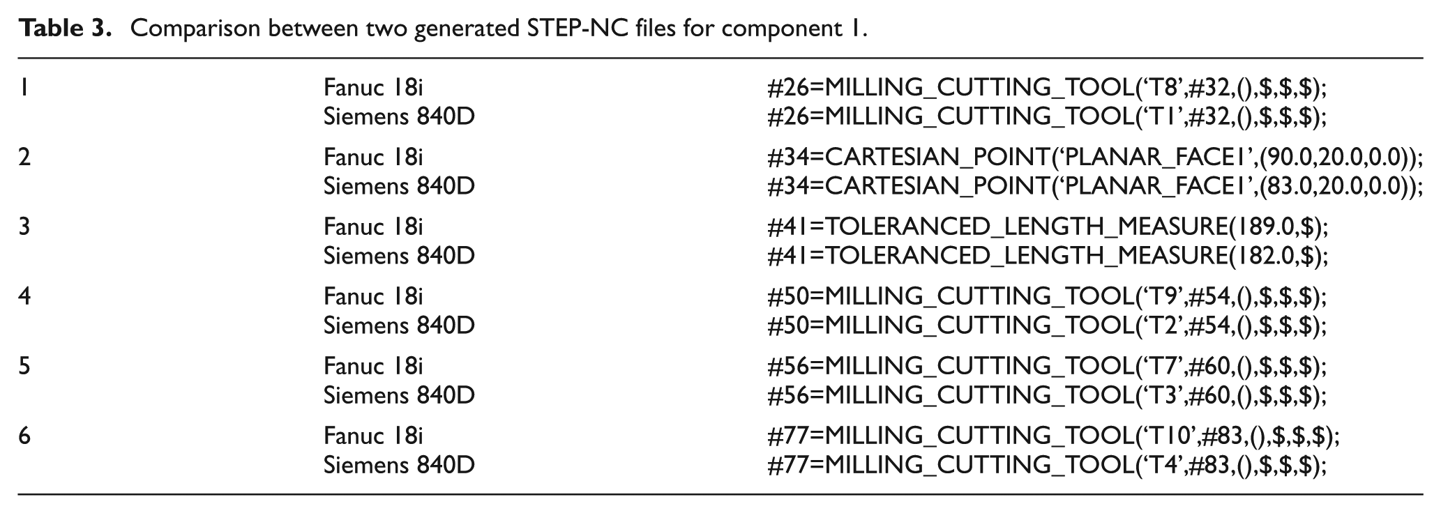
From Table 3, between these two STEP-NC files, there are six differences, four of which are tool names. It is common that tools with the same dimension have different names on two different machines. The other two differences (numbers 2 and 3) are due to the different starting points to mill the top surface. Actually, the difference starts from shopfloor changes to the Fanuc 18i part program. At the shopfloor, it was thought it is a good practice to place the tool a little further from the part and then cut into the material for safety reasons. It is the evidence that the meta-model proposed in this article can be used to capture the shopfloor knowledge from part programs. However, it does not make a difference to the features and the machining methods. Hence, the two STEP-NC files generated from Fanuc and Siemens part programs are semantically identical.
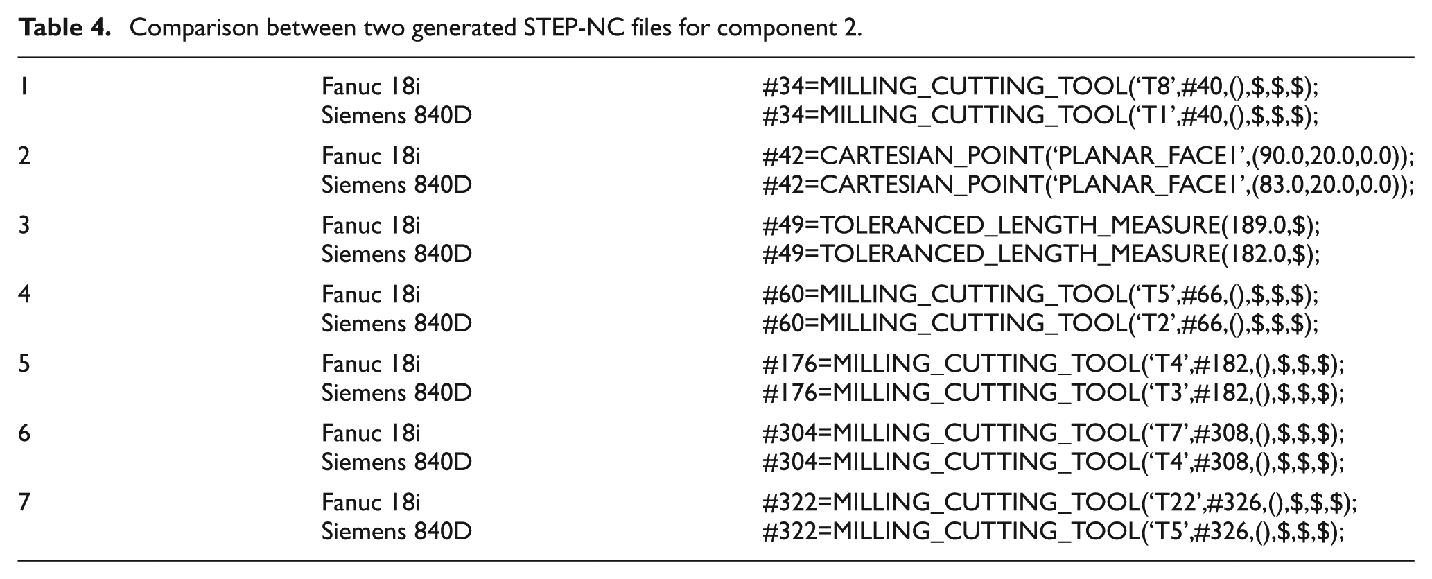
Similarly, for the two STEP-NC files generated by UPCi from part programs for component 2, the comparison has been conducted and differences have been listed in Table 4. The results are similar to the first component. Five differences are related to different tool names. Two differences are due to the modification of the starting point of the surface milling operation made at shopfloor. Semantically, the two STEP-NC files are identical.
Comparison between two generated STEP-NC files for component 2.
Conclusion
Due to the existence of many different part programming languages and the mechanism of part program generation, the shopfloor CNC machines have been isolated from other CAxs. The shopfloor knowledge cannot be captured and reused automatically. This article has realised a universal representation of different CNC programming dialects for the purpose of interoperability. A meta-model of CNC programming languages has been proposed. Programming specifications of CNC dialects have been modelled in XML format to realise the standardised translation of CNC dialects. The meta-model together with the XML description of CNC dialects provides versatile interface for knowledge capture and interoperability regardless of the programming dialects, which enables the UPCi to be an expansible system for new programming dialects. The results of the article show that the meta-model is a highly effective method to represent and interpret the process plan within part programs and capture the shopfloor knowledge. The integrity of the process plans in STEP-NC outputs and the identity between STEP-NC files have shown the efficiency of the meta-model. It is a universal method to represent part programs in different programming dialects, which has been validated by the case studies using two popular programming dialects with two components containing typical prismatic features. The meta-model coupled with UPCi proposes a novel technique to connect the shopfloor with upper stream planning departments and provides new thinking and perspective to capture and reuse the process knowledge from the shopfloor. The utilisation of STEP-NC as the representation of the process plan makes it neutral and standardised, and it is possible for the process plan to be interpreted and reused by other systems in the CAx chain.
Footnotes
Declaration of conflicting interests
The authors declare that there is no conflict of interest.
Funding
The work reported in this article has been undertaken as part of the research work in the EPSRC Innovative Manufacturing Research Centre at the University of Bath (grant reference GR/R67507/0). The authors gratefully acknowledge the support.