
Abstract
The machining of aerospace materials, such as metal matrix composites, introduces an additional challenge compared with traditional machining operations because of the presence of a reinforcement phase (e.g. ceramic particles or whiskers). This reinforcement phase decreases the thermal conductivity of the workpiece, thus, increasing the tool interface temperature and, consequently, reducing the tool life. Determining the optimum machining parameters is vital to maximising tool life and producing parts with the desired quality. By measuring the surface finish, the authors investigated the influence that the three major cutting parameters (cutting speed (50–150 m/min), feed rate (0.10–0.30 mm/rev) and depth of cut (1.0–2.0 mm)) have on tool life. End milling of a boron carbide particle-reinforced aluminium alloy was conducted under dry cutting conditions. The main result showed that contrary to the expectations for traditional machined alloys, the surface finish of the metal matrix composite examined in this work generally improved with increasing feed rate. The resulting surface roughness (arithmetic average) varied between 1.15 and 5.64 μm, with the minimum surface roughness achieved with the machining conditions of a cutting speed of 100 m/min, feed rate of 0.30 mm/rev and depth of cut of 1.0 mm. Another important result was the presence of surface microcracks in all specimens examined by electron microscopy irrespective of the machining condition or surface roughness.
Keywords
Introduction
By necessity, the components for aerospace applications should be manufactured from lightweight, durable and fatigue-resistant materials, such as alloys based on aluminium, titanium and stainless steel. In the continuing search for improved performance, metal matrix composites (MMCs) containing ceramic particles or whiskers in an aluminium or titanium alloy have been increasingly used because of their superior mechanical properties and relatively low density. However, similar to titanium alloys and stainless steels, MMCs are known to suffer from a low machinability rating, with optimal machining cutting conditions being dependent on factors such as cutting force, feed rate, depth of cut, tool path, cutting power, surface finish and tool life. 1 The additional complexity arising during the machining of this material is due to the presence of reinforcement particles that cause non-homogeneous deformation of the composite.2,3
The optimal machining conditions for MMCs have been the subject of much research in recent years, particularly because of their abrasive wear.4,5 For example, Pramanik et al. 6 investigated the influence of reinforcement particles on the machining of MMCs and found the presence of compressive residual stresses on the resulting machined surfaces. The surface roughness was controlled by the feed rate at a high feed rate, and the particle pull-out influenced the roughness when the feed rate was low. Furthermore, the reinforced particles facilitated chip breaking and induced compressive residual stresses. In another study, 7 the cutting forces, tool wear and surface roughness present during the turning of an A356/20/SiCp-T6 composite by a polycrystalline diamond (PCD) tool were evaluated. The rounding of edges, cracking and chipping occurred in all PCD inserts, where the predominant wear was observed in the flank face and was attributed to abrasion, which contributed to the increased cutting forces. The wear also deteriorated the rake surface, with the surface roughness found to increase with decreasing cutting speed at a constant feed rate.
The surface roughness of an Al/SiC (20 vol%) composite was also investigated for a turned composite bar using coarse grade PCD inserts under different cutting conditions 8 using analysis of variance (ANOVA) and artificial neural network (ANN) techniques. A multi-layered perceptron model was constructed with a back-propagation algorithm using depth of cut, cutting speed and feed as the input parameters and surface finish as the output parameter. Following the training of the ANN using 18 patterns, the model predicted the surface roughness. In another study, the influence of machining parameters on the surface finish of turned Al/SiC particulate composites utilising a second-order response surface model predicted the surface roughness with 95% confidence intervals within the considered ranges of the parameters. 9
The machinability of MMCs comprising an aluminium A356 alloy containing four different amounts of SiC particles was investigated during milling. The input parameters of cutting speed, feed and depth of cut were related to the cutting force and tool–work interface temperature. 10 An increased amount of SiC reinforcement resulted in a higher tool–work interface temperature and higher cutting forces. A study on the machinability of a ZA43 alloy reinforced with SiC particles (size: 60 μm; 5–15 wt%) during dry turning by uncoated and coated carbides 11 showed that the cutting speed, feed rate and depth of cut affected both surface finish and tool wear.
The relationship between cutting force and tool wear is important. This relationship was previously investigated during the drilling and turning of an A356/20/SiCp-T6 composite through the continuous measurement of the cutting forces. 8 Conversely, Gaitonde et al. 12 established the relationship between cutting conditions and machinability characteristics during the turning of MMCs (A356/20/SiCp-T6) using PCD tools. Response surface methodology was used to develop second-order mathematical models to determine the influence of cutting speed and feed rate on machining force, cutting power and specific cutting. ANOVA was further used to verify the adequacy of the mathematical models with parametric analysis, indicating that machining force and cutting power increased with increasing feed rate.
The tool life of single-layer, chemical vapour deposition diamond-coated tools is limited by abrasive flank wear due to rubbing between the newly created machined surface and the tool nose for the monolayer rough-coated tool. 13 By contrast, the tool life of a multi-layer coated tool is limited by coating peeling attributed to adhesive wear and cutting edge attrition. Similar tool wear phenomena but with reduced tool life were observed when the percentage of reinforcement increased.
Based on the above discussion, the influence of machining parameters on the surface finish of end-milled MMC components has been relatively lacking. Much of the research so far has focused on the cutting tool materials used because of the generation of large thermal loads in the cutting zone; therefore, extreme levels of diffusion have caused high tool wear. 14 A larger number of recent studies have investigated the machining of Al/SiC MMC materials with particular attention to tool life, surface finish and cutting parameters. The impact of the cutting parameters for this material4,15,16 has been shown to be important for machining.
Machining operations for aerospace and traditional materials generate significant quantities of waste because of their use of cooling liquids. Aerospace companies are compelled to put in place expensive waste disposal procedures to reduce their impact on the environment. Based on such reasoning, this study investigated the influence of machining parameters (cutting speed, feed rate and depth of cut) on the surface finish of an MMC subjected to end milling without coolant (i.e. dry cutting). Research previously conducted on the dry machining of traditional materials 17 guided the selection of machining conditions in the present work.
Surface finish is a critical parameter in any machining operation in terms of machinability, useful tool life and quality. Surface roughness represents the random and repetitive deviations of a surface profile from the nominal surface. For peripheral milling, the following equation can be used to calculate the surface roughness parameter of peak-to-valley height, Rma1,18
where R is the cutter radius and ft is the feed per tooth. Equation (1) indicates that decreasing the feed rate should improve the surface finish of the workpiece. This simplified formula assumes the tool path to be a circular arc, whereas Martellotti 19 showed the path of a milling cutter to be trochoidal, with the formula for calculating surface roughness in this case being considerably more complicated. Nonetheless, the qualitative relationship between surface roughness and feed rate remained the same; that is, surface roughness was approximately proportional to the square of the feed per tooth. 1
Experimental procedure
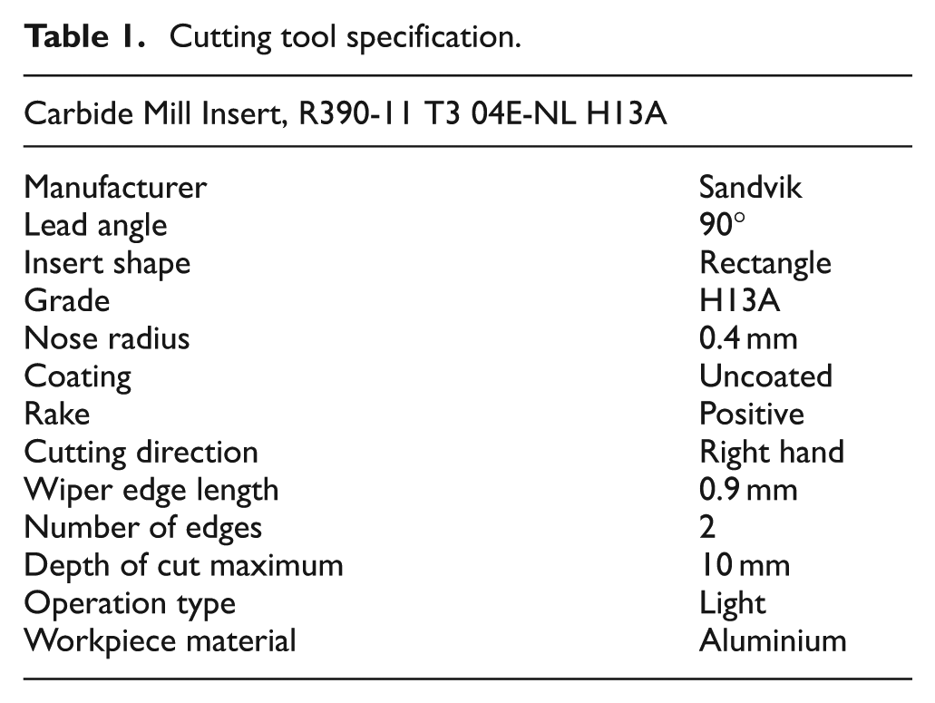
The material under investigation was a 2124 aluminium alloy reinforced with 20 vol% of boron carbide (B4C) particles of size 3 μm (Grade AMC220bc; Materion Aerospace Metal Composites Ltd) with a yield strength of 458 MPa. Workpiece composite blocks of 65 mm × 30 mm × 25 mm were prepared for the machining tests, with approximately 15 mm of the block height required for clamming. End-milling cutting was performed at the periphery of the block, which enabled a 6-mm axial depth of material to be removed with the tool. When the tool was fully engaged, a total length of cut of 190 mm for each workpiece was obtained. The mode of milling used was up milling performed without any coolant. Testing was conducted on a three-axis Leadwell V30 CNC vertical machining centre with a maximum machine table movement of 760 mm × 410 mm × 520 mm along the x-, y- and z-axes, respectively. A 12-mm-diameter cutting tool using a single uncoated carbide insert (R390-11 T3 08E-NL H13A; Sandvik) was used to simplify the cutting analysis. Table 1 shows the insert geometry specifications. Each cutting test used a new insert edge to avoid possible tool wear effects.
Cutting tool specification.
Following machining, the surface roughness of the workpiece was analysed using a portable stylus-type surface roughness tester (SJ-201; Mitutoyo Surftest). Measurements were taken at 15 mm intervals along the workpiece periphery. Aside from surface roughness, other factors such as surface integrity, for example, the presence of microcracks, are also known to be considered when judging the quality of machining MMC materials. Thus, the surface finish of the selected specimens taken from the workpiece was investigated using scanning electron microscopy (SEM) (40XVP; Zeiss Evo) at 15 kV accelerating voltage after coating the specimen surfaces with a thin (approximately 5 nm) layer of platinum to reduce charging effects.
Experiment design
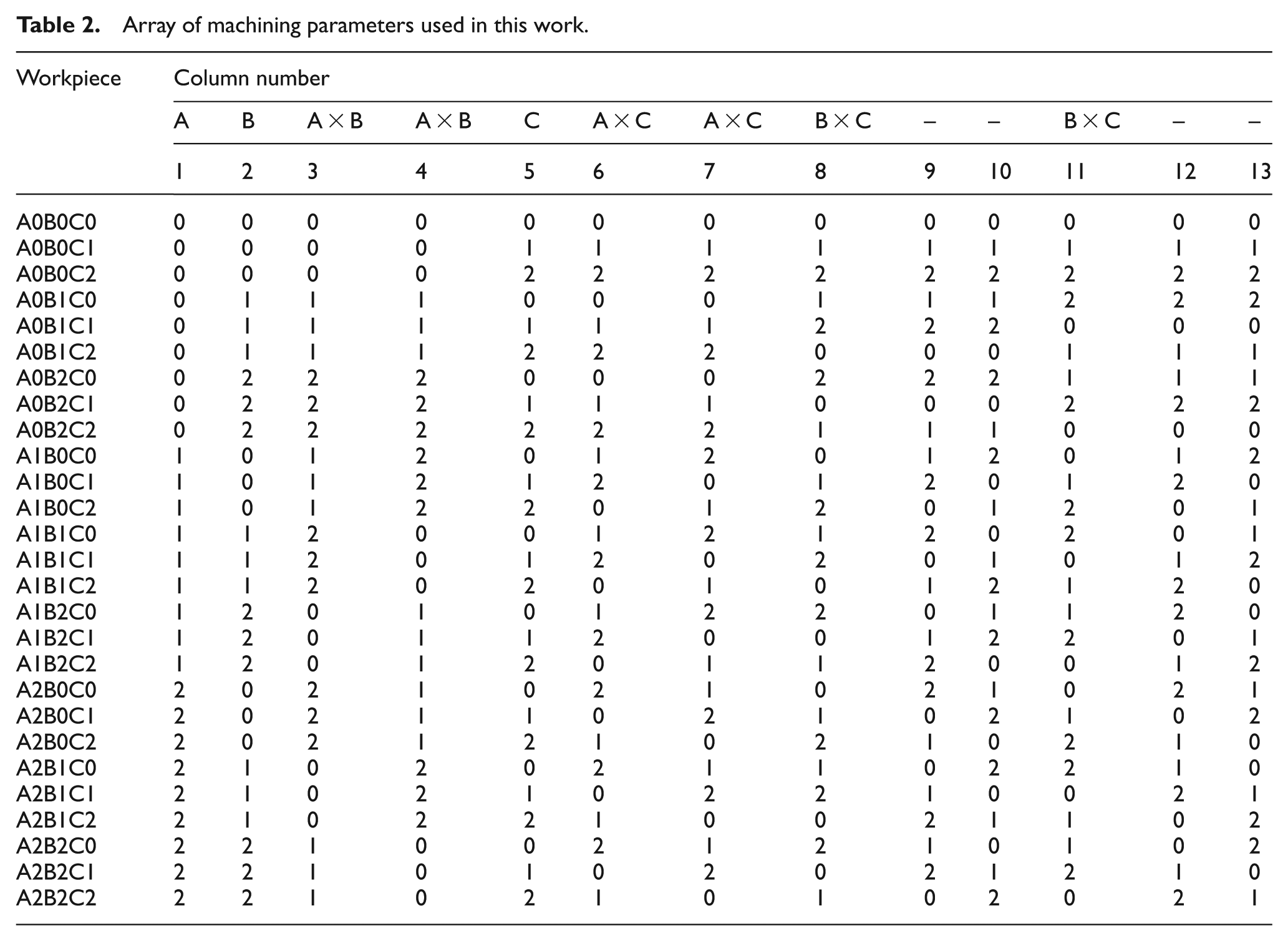
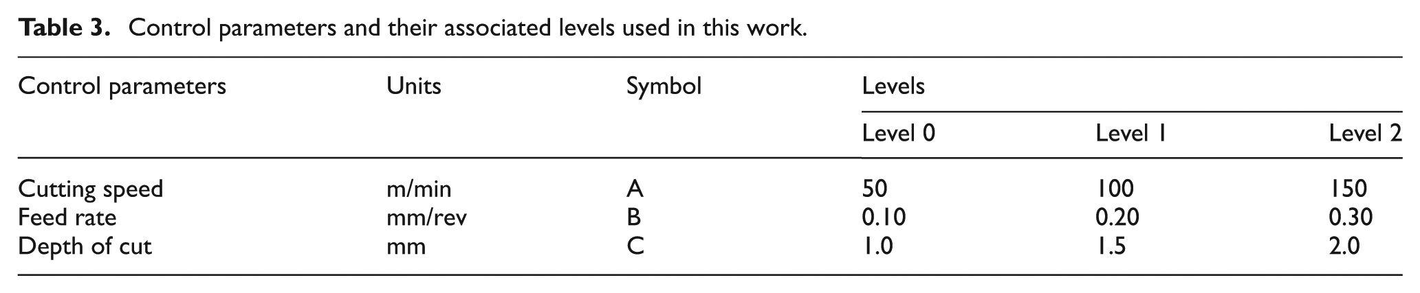
To obtain robust data, the experiments were planned using Taguchi’s orthogonal array. A three-level, three-parameter L27 (33) orthogonal array was selected for the cutting tests. The experimental runs (n = 27) were conducted as shown in Table 2, which presents the interactions between (i) cutting speed and feed rate, (ii) feed rate and depth of cut and (iii) cutting speed and depth of cut. The values of the selected control parameters and levels are shown in Table 3.
Array of machining parameters used in this work.
Control parameters and their associated levels used in this work.
The results from this work were analysed using two statistical tools, namely, Pareto ANOVA and Taguchi’s signal-to-noise (S/N) ratio analysis. Pareto ANOVA identified the degree to which each control parameter affected the surface roughness of the machined workpiece. It had the added advantage that using the Pareto principle, only 20% of the total machining configurations would be required to generate 80% of the benefits of completing every test configuration. 20 Pareto ANOVA is a simplified ANOVA method that does not require an ANOVA table and does not use F-tests. Therefore, detailed knowledge of the ANOVA method is not required. A thorough treatment of the Pareto ANOVA method can be found by Park. 21
The authors used a Taguchi 22 statistical method to establish the optimum cutting parameters for machining the AMC220bc composite, enabling the machining parameters to be robustly tested on their machining performance. 8 The Taguchi method applies the S/N ratio to optimise the outcome of a manufacturing process. The S/N ratio was calculated using the following formula: 23
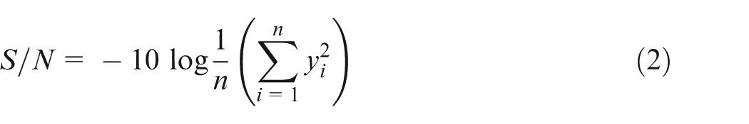
where n is the number of observations and y is the observed data. This formula is suitable for quality characteristics in which the adage ‘the smaller the better’ holds true. The results from this formula suggest that the greater the magnitude of the S/N ratio, the better the result will be because it yields the best quality with the least variance.
Results and discussion
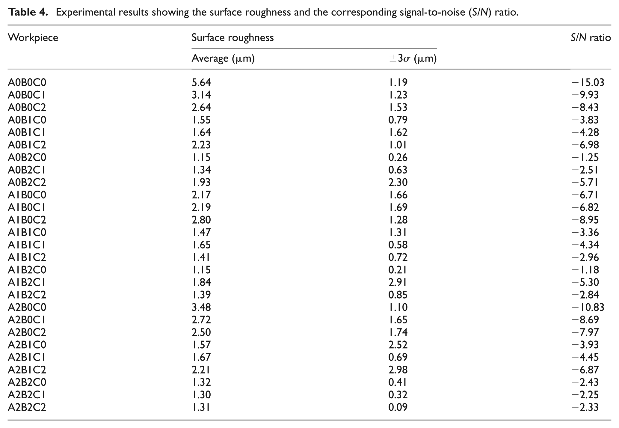
Pareto ANOVA was used to investigate how the 27 different combinations of machining parameters influenced the dimensional and surface roughness of the specimens. Table 4 presents the experimental results and corresponding S/N ratios. Figure 1 shows the typical scanning electron micrographs of the AMC220bc composite following a machining operation. The boron carbide particles were difficult to distinguish in the secondary electron image (Figure 1(a)). However, they become clearly visible in the backscattered electron image (Figure 1(b)) with black equiaxed particles with a typical diameter of 1–4 μm because of the large difference in average atomic number, Z, between the boron carbide and the aluminium alloy matrix. As shown in Figure 1, the presence of surface microcracks, particularly at the interface between the B4C particles and the aluminium matrix, was also observed. This finding highlights the assertion of previous researchers 24 that surface integrity is an important parameter (aside from surface roughness) that must be considered when judging the quality of machining MMC surfaces. Note that surface microcracks were found in all specimens irrespective of machining condition. Therefore, the interpretation of machining tests for MMCs should be treated differently compared with that for traditional alloys, particularly the recommendation that surface roughness measurements should always be used in conjunction with SEM to judge the quality of the machined surface.
Experimental results showing the surface roughness and the corresponding signal-to-noise (S/N) ratio.
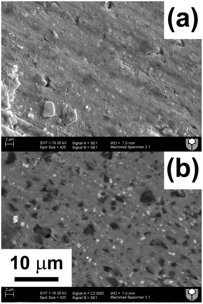
Scanning electron micrographs of the boron carbide particle-reinforced aluminium alloy (AMC220bc) following a typical machining operation (specimen A2B0C0): (a) secondary electron image and (b) backscattered electron image.
Surface roughness
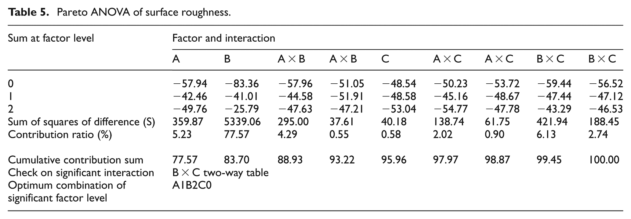
The examination of the surface roughness data presented in Table 4 showed Ra to vary between 1.15 μm for the A0B2C0 and A1B2C0 specimens and 5.64 μm for the A0B0C0 specimen. A response graph illustrating the influence of the machining parameters on the surface roughness is presented in Figure 2. Clearly, the feed rate parameter (B) had the most significant effect on surface roughness, followed by cutting speed (A) and depth of cut (C). The interaction B × C also affected the machining process. The medium level of cutting speed (100 m/min) was determined to result in the lowest surface roughness. As the interaction of B × C was significant, the optimum combination for factors B and C to achieve a low surface roughness was B2C0. Thus, the optimal combination to achieve low surface roughness was A1B2C0, that is, cutting speed of 100 m/min, feed rate of 0.3 mm/rev and depth of cut of 1.0 mm. The Pareto ANOVA for surface roughness given in Table 5 confirmed that the main parameter to influence mean surface roughness was feed rate, with a contribution of 77.6%. All the other parameters, both individual and their interactions, had a minimal effect on the surface roughness.
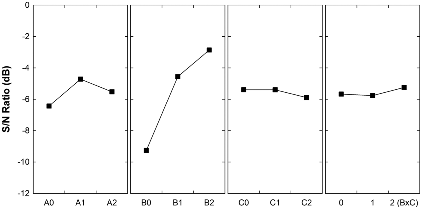
Response graph showing the influence of machining parameters on the surface roughness of a boron carbide-reinforced aluminium metal matrix composite (AMC220bc).
Pareto ANOVA of surface roughness.
Expected trends
Generally, feed rate significantly changes the cutting force in a non-linear manner, and increasing the cutting speed slightly reduces the cutting force. Cutting speeds in the low range tend to form a built-up edge that disappears at high cutting speeds. Depth of cut also changes the cutting force significantly but the relationship is linear. Therefore, varying the depth of cut and the feed rate yields a method of controlling cutting force. 25 Machining with a positive tool orthogonal rake angle also decreases the cutting force but at the expense of a greater possibility of tool failure.
Trends in surface roughness
The influence of machining parameters on the surface roughness of MMCs is complex compared with that of traditional alloys. The size and the amount of the reinforcement phase are known to influence surface roughness. 26 The response graph from the S/N ratio analysis with respect to surface roughness (Figure 2) showed that cutting speed had a varying effect on surface roughness. For example, when the cutting speed increased from Level 0 to Level 1, the quality of the surface improved, but when the speed was further increased to Level 2, the quality of the surface deteriorated. By contrast, when the depth of cut increased from Level 0 to Level 1, the surface roughness remained constant but then increased as the depth of cut further increased to Level 2. However, the overall influence of cutting speed and depth of cut on surface roughness in the present work was consistent with that in previous research.1,27 These trends are attributed to the plastic deformation of the machined surface from the built-up edge expected to exist in aluminium-matrix MMCs9,28 or from material softening, particularly at the higher temperatures expected from dry machining. 29 In contrast to the influence of cutting speed and depth of cut on surface roughness, the influence of feed rate on surface roughness (Figure 2), which showed surface roughness to decrease as the feed rate increased, was opposite to the conventional wisdom that the surface roughness should increase with the feed rate. Indeed, the results were so unexpected that the authors repeated the tests to confirm the validity of the trend.
As mentioned above, the machining tests indicated that the surface roughness improved with the increased feed rate. To investigate this further, the surfaces of the selected specimens were examined using electron microscopy. The SEM images of the machined surfaces at low and high magnification are presented in Figures 3 and 4, respectively. Analysis of the SEM images suggested that the machined surfaces for all specimens could be divided into three main types, as shown in Figure 5. The first type was identified as ‘fish scale’ (Figure 5(a)), and it occurred in approximately 30% of all specimens, particularly in those with the lowest cutting speed (50 m/min; that is, A0 specimens) and/or lowest feed rate (0.10 mm/rev; that is, B0 specimens). The ‘fish scale’ surface is generally associated with the largest surface roughness values encountered in this work. The second type of surface also occurred in approximately 30% of all specimens and was identified as ‘medium’ (Figure 5(b)). This surface type appeared to have the elements of the ‘fish scale’ surface but with smaller features in terms of both length and amplitude. It is suggested to be a transitional surface type associated with medium surface roughness. The ‘medium’ surface was mainly observed in specimens subjected to the highest cutting speed of 150 m/min (i.e. A2 specimens). The final surface type was encountered in approximately 40% of all specimens and was identified as ‘smooth’ (Figure 5(c)). This surface feature was characterised by large ‘smooth’ regions interrupted by rougher parallel lines. The analysis of several specimens under varying machining conditions showed the mean distance between the parallel lines to be 297 μm with a range of 285–305 μm. The ‘smooth’ surface type was associated with the lowest surface roughness specimens, and it tended to occur in the specimens subjected to feed rates of 0.20 and 0.30 mm/rev (i.e. B1 and B2 specimens, respectively).
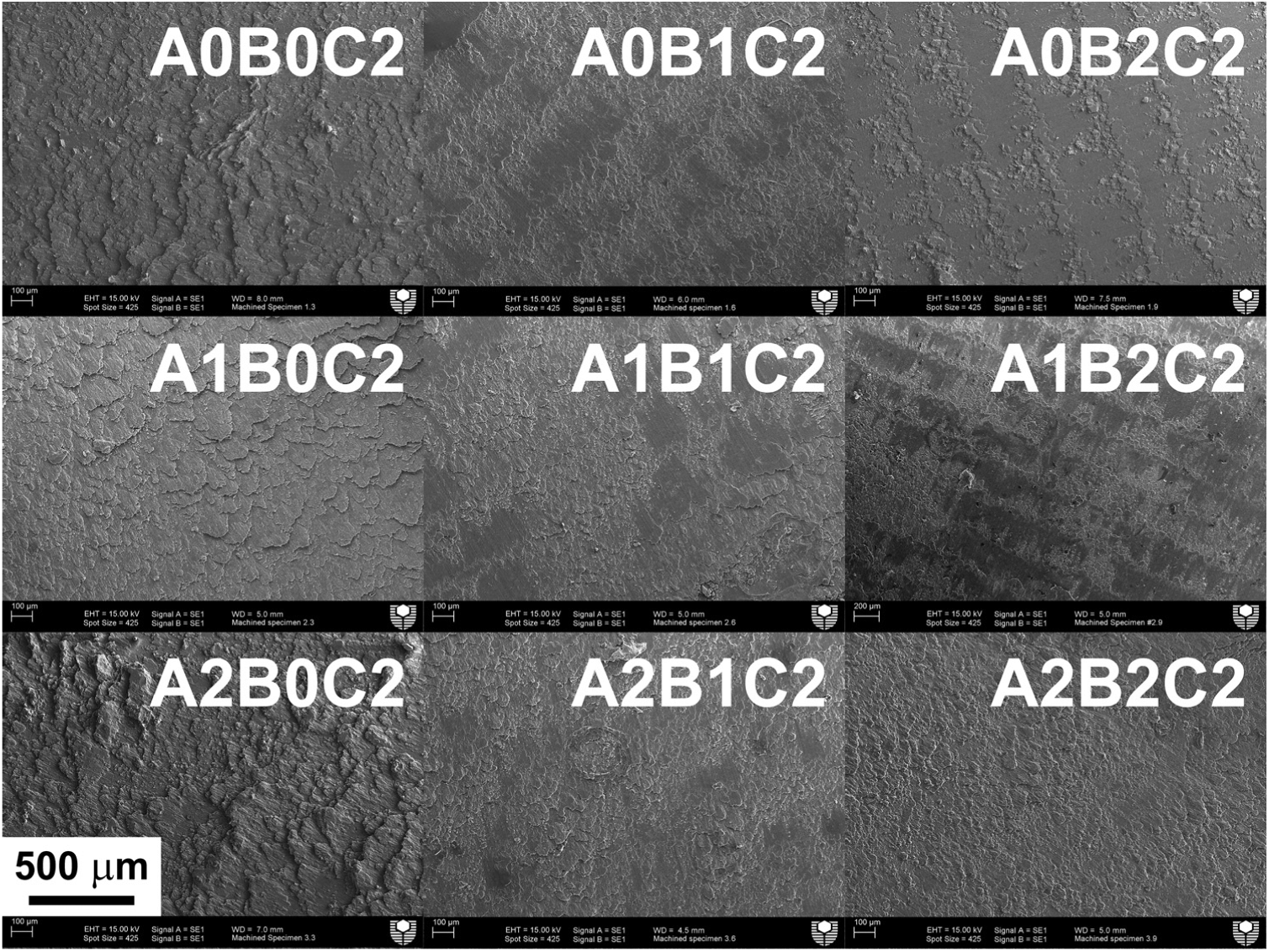
Scanning electron micrographs showing the surface finish of selected machined boron carbide particle-reinforced aluminium composite (AMC220bc) specimens at low magnification (nominally ×50).
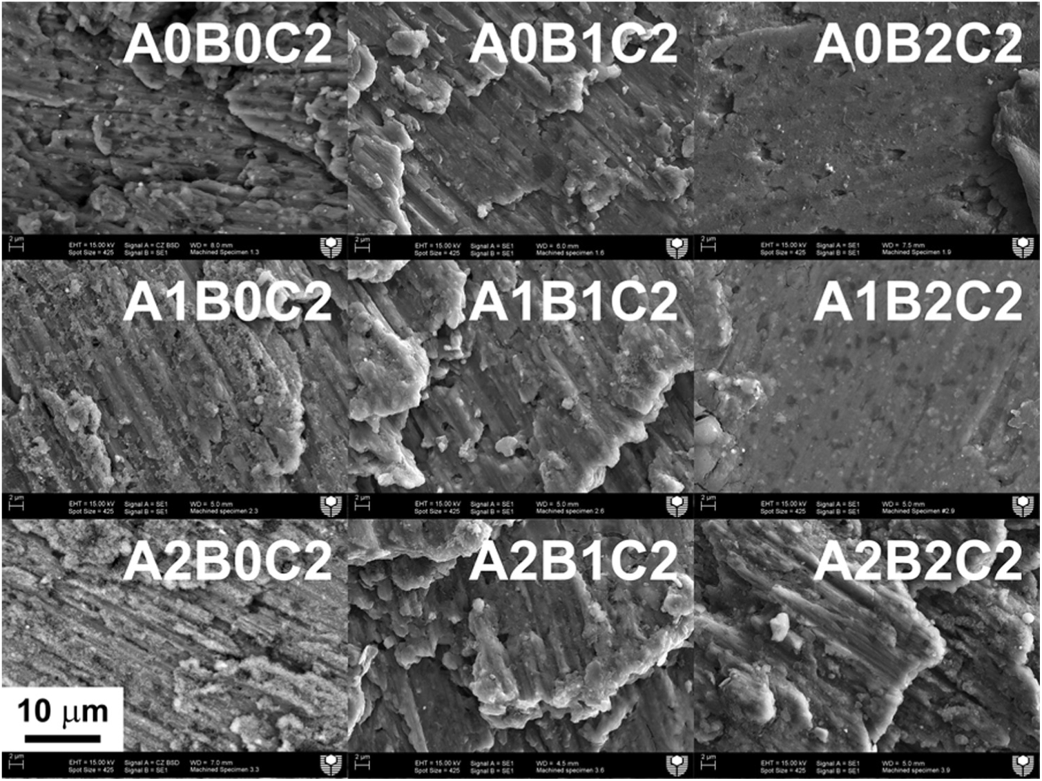
Scanning electron micrographs showing the surface finish of selected machined boron carbide particle-reinforced aluminium composite (AMC220bc) specimens at high magnification (nominally ×2000).
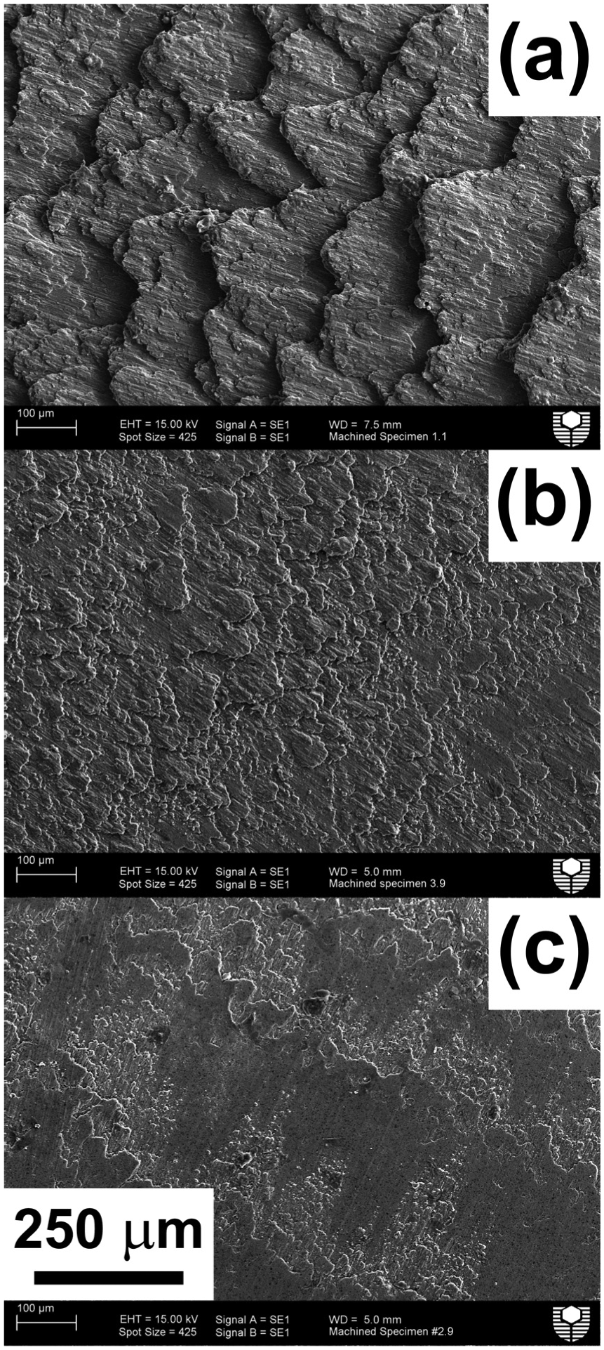
Scanning electron micrographs showing the main types of surface finish achieved after machining a boron carbide particle-reinforced aluminium alloy (AMC220bc) composite: (a) ‘fish scale’ (specimen A0B0C0), (b) ‘medium’ (specimen A2B2C2) and (c) ‘smooth’ (specimen A1B2C2).
The examination of the micrographs in Figure 3 confirmed the influence of the feed rate. The B0 series of specimens (i.e. 0.1 mm/rev, an example of which is given in Figure 6) had the roughest surface finish, with the ‘fish scale’ features clearly visible in the low magnification image (Figure 6(a)). Further magnification revealed the details of the edge of the ‘fish scale’ features (Figure 6(b)), with numerous microcracks observed. The highest magnification image (Figure 6(c)) revealed the presence of additional microcracks together with parallel indents, which are attributed to the gauging of the B4C particles across the softer aluminium base alloy and similar to those observed in SiC particle-reinforced aluminium composites. 13 By contrast, the best surface finish was achieved in the B2 series of specimens (an example of which is given in Figure 7), with the ‘smooth’ surface features and associated rougher parallel lines clearly visible at low magnification (Figure 7(a)). The rougher parallel lines in this case were estimated to be separated by 305 μm. A higher magnification image (Figure 7(b)) adjacent to one of the parallel lines indicated the rougher region to be associated with shallow (2–4 μm), flat-based craters. The crater floor exhibited evidence of parallel indents, suggesting that these features might have formed because of the gauging of the reinforcement particles. One hypothesis worthy of further investigation is that these craters may have formed through the action of reinforcement particles within the built-up edge interacting with the specimen surface. The highest magnification image for this specimen (Figure 7(c)) showed the presence of a locally flat surface interspersed with microcracks and surface voids. A closer inspection showed the microcracks to be due to the debonding between the reinforcement particles and the base alloy. The surface voids were attributed to the following: (i) the local removal of the base alloy adjacent to the reinforcement particles because of the action of shear stresses and (ii) the removal of reinforcement particles due to the action of the cutting force. Presumably, the degree of removal of the reinforcement particles to create surface voids would depend on the strength of the interfacial bonding and would be greater for particles subjected to machining forces below the particle midplane. The angle between the particle and the incoming force would provide a force component perpendicular to and out of the surface plane. Whereas the surface of specimen A0B2C2 in Figure 7 showed the presence of microcracking and surface voids, the specimen with a higher cutting speed (i.e. A1B2C2) exhibited a similarly flat surface but with noticeably less, albeit still present, microcracking and the absence of surface voids. Thus, the A1B2C2 machining condition would be preferred to A0B2C2 because of the significantly lower surface damage on the micron scale (which could be difficult to detect using optical microscopy).
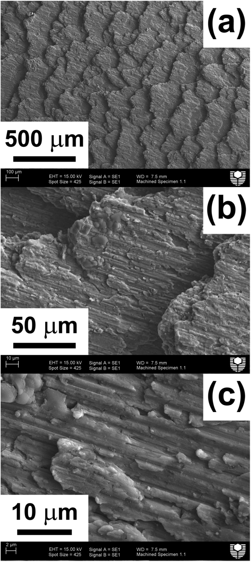
Scanning electron micrographs showing the surface finish of a boron carbide particle-reinforced aluminium alloy (AMC220bc) composite (specimen A0B0C2) machined at a low feed rate (0.10 mm/rev) at different magnifications.
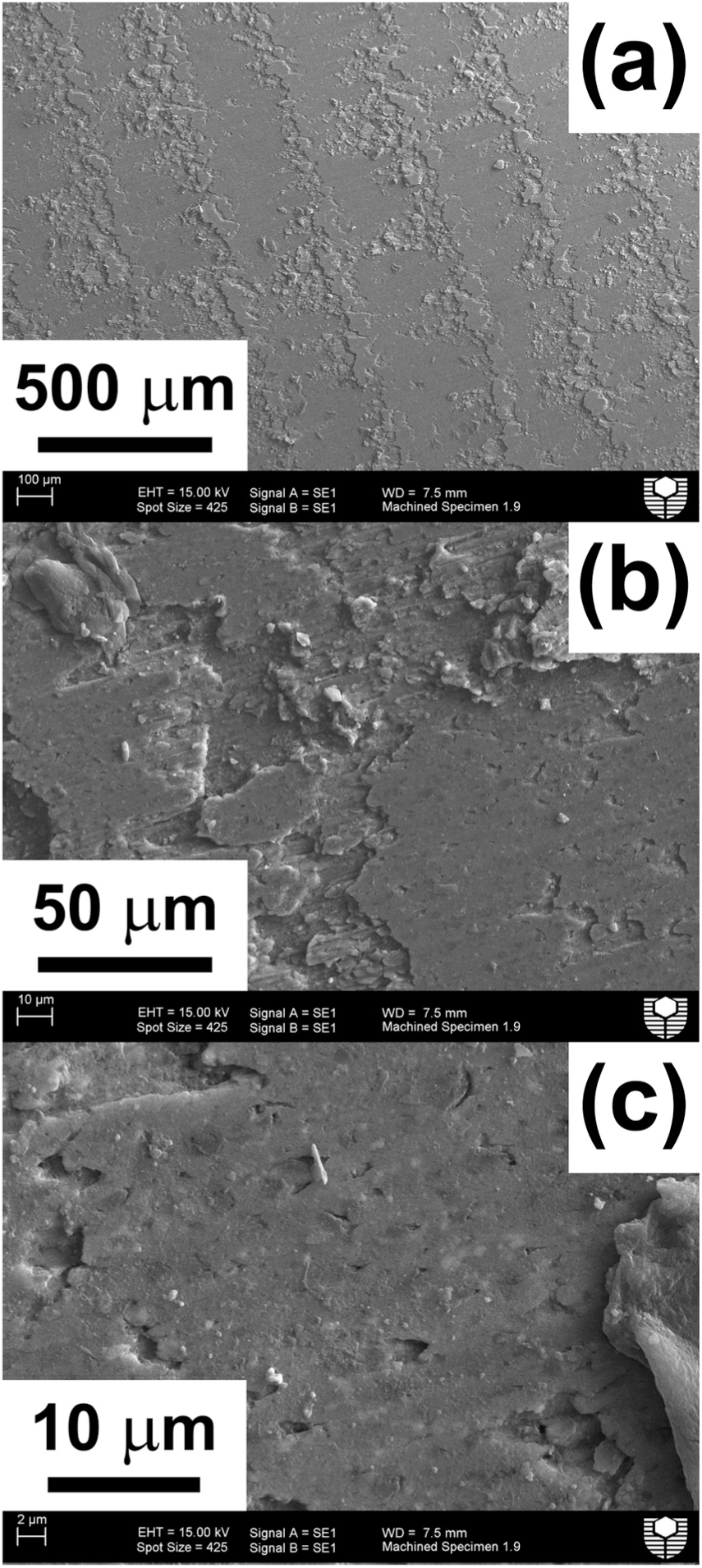
Scanning electron micrographs showing the surface finish of a machined boron carbide particle-reinforced aluminium alloy (AMC220bc) composite (specimen A0B2C2) machined at a high feed rate (0.30 mm/rev) at different magnifications.
Every specimen examined by SEM was found to contain surface microcracks due to the debonding between the reinforcement particles and the matrix. Therefore, the authors recommend that the relative importance of surface roughness and microcracking on properties such as fatigue lifetime be the subject of future research. The influence of surface roughness on the mechanical performance of MMCs is assumed to be of lesser importance, particularly when compared with that of traditional alloys, because of the presence of surface microcracking.
Overall, the improvement in the surface finish with the increasing feed rate was considered due to the difference in properties of the MMC compared with those of conventional alloys, particularly the base aluminium alloy, for the materials under investigation. The MMC in this work produced a better surface finish at a faster feed rate, thus decreasing the manufacturing time yet maintaining a better surface quality product. Furthermore, the interaction of the reinforcement particles with the machining operation may explain the previous observation 6 that the surface roughness of MMCs may be larger than that of the base alloy at low feed rates but smaller than that of the base alloy at higher feed rates.
In contrast to that of feed rate, the influence of cutting speed was typical of that of traditional alloys. That is, as the cutting speed increased, the surface finish initially improved and then reached a maximum. After which, further increases in the cutting speed degraded the surface finish. This result suggests that an optimum cutting speed exists, and its value needs to be determined by additional testing.
Conclusion
The authors investigated the influence of cutting speed (50–150 m/min), feed rate (0.10–0.30 mm/rev) and depth of cut (1.0–2.0 mm) on the surface finish of an end-milled MMC composed of an aluminium alloy reinforced with 20 vol% of boron carbide particles in the approximate size range of 1–4 μm. A key result of this work was that the highest feed rate minimised the surface finish, opposite to that expected for standard alloys. Furthermore, all specimens examined by SEM contained surface microcracks irrespective of the machining condition and surface roughness. Overall, the optimum machining configuration for the composite under investigation was high cutting speed combined with high feed rate, which would also maximise the material removal rate. Therefore, this study suggests that boron carbide particle-reinforced aluminium composites have the potential to be machined in an economic manner. Determining the optimum cutting parameters for these materials is an opportunity for future research.
Footnotes
Appendix 1
Declaration of conflicting interests
The author(s) declared no potential conflicts of interest with respect to the research, authorship, and/or publication of this article.
Funding
The author(s) received no financial support for the research, authorship, and/or publication of this article.