
Abstract
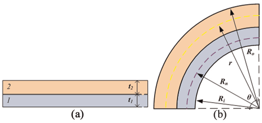
In this article, an advanced analytical formulation is developed to predict thickness change of an aluminum/copper clad sheet. Springback analytical formulation is also introduced using the combination of advanced and primary bending theories in air bending process. Experiments were performed to verify analytical results and to investigate the effect of different geometrical parameters such as punch stroke, die opening, punch radius and setting condition on the springback. It was observed that die opening had the most striking effect, while setting condition had a negligible effect on springback. On the other hand, setting condition played a crucial role on thickness change in bent clad sheets. Clad sheet thickened in the Al/Cu setting condition, while in the Cu/Al setting it thinned. Finite element method simulation was also applied to verify analytical predictions of the thickness change and study stress distribution in the layers of the clad sheet. Good correlation was observed between analytical and numerical results.
Introduction
In sheet metal industries, bi-layer clad laminated sheets are increasingly applied for manufacturing of various parts due to their characteristics such as high stiffness/weight ratio, special thermal and electrical behavior and wear and corrosion resistance. There are several processes to produce clad metals, namely, co-extrusion, diffusion bonding, hot or cold compression, friction stir welding, explosive welding, adhesive and cold or hot roll and accumulative roll bonding.1,2 Kaya et al. introduced a novel approach in diffusion welding of the copper–stainless steel clad sheets. Applying an auxiliary electrical current to the bonding sheets, they improved the strength of the bonding in diffusion welding process. 1 Li et al. presented a novel approach to fabricate Al/Ti clad sheets using multi-pass friction stir welding process. They also reported good bonding quality for this process. 2 Cladding different layers with different properties by roll bonding method needs some additional preparations, including surface preparation and heat treatment. Many parameters affect the cladding strength. Yan and Lenard 3 determined the optimum parameters such as rolling speed, entry temperature and normal pressure in cold and warm roll bonding of aluminum sheets. Bay et al. analytically investigated the effect of surface expansion and reduction on bonding strength of various clad sheet metals. It was observed that to bind the layers, surface expansion and reduction should pass a threshold. The effect of scratch brushing, Ni plating and friction on bond strength was also discussed. 4 Madaah-Hosseini and Kokabi 5 reported that increasing friction during rolling with no lubricant would result in the maximum weld efficiency. Abbasi and Toroghinejad 6 studied the effect of rolling speed, initial thickness of the clad components, rolling temperature and rolling reduction on the bond strength of copper clad sheets. Soltan Ali Nejad and Haerian Ardakani 7 reported that increasing pre-heat temperature has a positive effect on roll bonding strength of bi-layer steel–aluminum clad sheets. Buchner et al. 8 investigated the influence of grinding direction of initial sheets, pre-heat treatment and post-heat treatment on bonding strength of aluminum–steel clad sheets. In this article, cold roll bonding (CRB) of Al/Cu clad sheets has been performed considering all reported studies.3–8
Springback violates the product’s shape precision; therefore, it should be compensated. Since studying springback, whether to avoid or compensate it, is appealing, many studies focused on springback behavior in bending processes. Behrouzi et al.9,10 used an analytical inverse modeling to compensate springback in V-bending and made an iterative die shape design to compensate springback. Shim and Kim 11 proposed laser scanning to compensate springback after sheet stamping and provided a relation between bending radius and laser scanning length.
Rahmani et al. investigated the springback–spring forward phenomena in anisotropic sheets using numerical and experimental approaches. They studied the effect of punch radius, sheet thickness and sheet orientation corresponding to the rolling direction on the springback and spring forward in V-bending process. 12 Mori et al. investigated the springback of the ultra light steel in V-die bending controlled with a computer numerical control (CNC) servo press. The effect of the final sheet reduction in bottoming, forming speed and holding time at the end of the forming was investigated. 13 Farsi et al. 14 studied springback in wipe-bending process of the perforated sheets with oblong cuts using experimental and numerical approaches, and the effect of different process parameters and hole’s size on springback was investigated. Choudhury and Ghomi 15 investigated the effect of process parameters, and their combinations, on springback in V-die bending using design of experiments and Taguchi method. Lee et al. 16 applied an analytical approach in springback prediction of magnesium alloys in stretch bending process. Different hardening behaviors of the material in tension and compression were taken into account.
Analytical modeling of air bending consists of simplifying assumptions on sheet geometry, contact condition, material and stress-state modeling. De Vin 17 revealed the dependency of the accuracy of air bending process modeling on simplified assumptions. Many researches applied different assumptions to analytically model the air bending process. Gardiner studied analytical springback prediction in pure bending for rigid plastic materials and provided springback curves for different punch radius/sheet thickness ratios in industrial bending processes. In the analytical formulation, simultaneous plane strain and plane stress assumptions were used and sheet thinning was ignored. 18 Sidebottom and Gebhardt 19 analytically predicted springback in bent plates and beams assuming simultaneous plane strain and plane stress states. In analytical formulation, non-linear hardening behavior of the material was modeled by series of the infinitesimal lines. Yu and Johnson studied analytical springback prediction of rigid linear hardening sheet metal in the air bending process. In their model, bent sheet was divided into two regions. The first region, which locates near the punch nose, is in the plastic state, while the second region is in the elastic state. They assumed that sheet curvature is a cubic polynomial function and during air bending, sheet does not wrap around punch nose. 20 Wang et al. analytically predicted air bending springback using primary bending theories. They divided bending zone into three consecutive regions: (1) plastic zone under the punch tip, (2) elastoplastic zone and (3) elastic zone. It was assumed that sheet would wrap around the punch tip during air bending process. Required punch stroke, bending angle, springback angle and contact angle were computed by giving final desired angle. 21 Asnafi developed an analytical formulation to investigate springback in air bending process of thick sheets. In this developed formulation, primary bending theory was assumed and sheet did not wrap around punch tip. With the assumption of the linear moment distribution along the sheet length, sheet bending radius was calculated both in forming and after forming. 22 Jian et al. 23 applied a primary elastic bending theory to introduce the term elastic-limit-bend-angle and applied this definition for prediction of springback of the sheet metal in air bending process. Kim et al. developed previous model to consider neutral fiber shift in plastic zone and considering sheet thinning in plastic and elastoplastic zones. In this model, non-quadratic Hill yield criterion was applied. 24 Heller and Kleiner proposed an air bending analytical model in which sheet was divided into several segments. Pure plain strain bending condition was assumed in each segment and springback was predicted using advanced bending theories considering sheet thinning and neutral fiber shift. 25 Zhuan et al. analytically predicted springback considering sheet thinning, transverse stress and punch contact pressure using quadratic Hill yield criterion. Simple geometry for the sheet, including circular and straight parts, was assumed and the deformation and springback of the straight part were neglected. 26
Although many reports are available on forming behavior of mono-layer sheets, fewer reports concentrated on clad sheets. Hino et al. investigated draw bending of aluminum/stainless steel clad sheets and side wall curvature after the draw bending. The effect of strength difference between layers (yield strength and Young’s modulus), setting condition, thickness ratio and drawing force on the side wall curvature was studied both analytically and experimentally. 27 Jalali Aghchai et al. 28 investigated the formability of Al/St clad sheets using M–K theory and experiments. Forming limits of the bi-metallic sheet were also compared with its fabricating mono-layer sheets. Yilamu et al. studied air bending process of aluminum/stainless steel clad sheets numerically and experimentally. They investigated the effect of setting condition on both bending and springback angles and sheet thinning. Results revealed that setting condition was not so influential on springback angle but it affected bending behavior and sheet thinning. They also investigated the effect of hardening model on the accuracy of springback prediction. Results showed that kinematic hardening model, which describes Bauschinger effect, accurately predicted springback, while isotropic hardening rule underestimated springback. It was shown that when the softer layer was inside the bend-punch side, even sheet thickening might happen. 29
It can be implied from the presented reports that the effect of geometrical process parameters such as punch stroke, die opening and punch radius on bending behavior of the clad sheets has not received so much attention. Also, the springback and sheet thinning behaviors of the clad sheets have not been investigated analytically. Understanding clad sheet springback behavior and thickness change in each layer simplifies material selection and usage of such clad sheets.
In this article, the effect of process parameters and setting condition on springback and sheet thinning of aluminum–copper clad sheets is presented. First, analytical prediction of springback of clad sheets is presented using combined advanced and primary bending theories. Analytical calculations are faster and simpler than finite element method (FEM) simulations and can give some useful information about the subject. Numerical FEM simulation of air bending and the following springback was previously carried out by Yilamu et al. 29 Therefore, FEM simulation of springback is not explained in detail here. FEM simulation results will be used to verify analytical results of thickness change. By using results of FEM simulation and analytical procedure, the thickness change with setting condition will be explained.
Analytical formulation
In this analytical study of air bending, it is assumed that sheet conforms to punch curvature in punch-sheet contact zone.
21
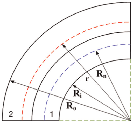
It is also assumed that moment distribution is linear along sheet length in the way that maximum bending moment acts in punch-sheet contact zone and no moment acts on the sheet in die shoulders. Figure 1 shows moment distribution and sheet geometry in loading condition. In air bending process, according to Figure 1, sheet can be divided into four regions of “oc,”“ce,”“ed” and “df” along its length. Point “o” is the symmetrical point of the sheet and is the origin of x–y linear coordinate system. In the first region, “oc” sheet undergoes plastic deformation and internal bending radius of sheet equals punch radius. Therefore, a constant bending moment, Mp, is applied on the sheet in this segment. In the next region, “ce,” sheet undergoes elastic–plastic deformation, while sheet deforms only elastically in the third region, “ed.” The fourth region “df” is free part of the sheet which remains rigid. The angle
Assumed bending distribution along sheet length and sheet geometry.
Defining another coordinate system, r–s, is convenient to analyze sheet deformation along its length. Point “c” is the origin of this curve-linear coordinate system. Smax, which equals sheet length between points “c” and “d” in Figure 1, is the maximum free length of the sheet in half of the die opening.
In analytical study, a combined advanced primary plane strain bending theory is used. It is assumed that in “oc” segment, because of the smaller bending radius/sheet thickness ratio, transverse stress and sheet thinning are not negligible. Therefore in this region, advanced bending theory in which the neutral fiber shift is taken into account is considered. In other regions, the assumptions of the primary bending theory are considered where sheet thinning, neutral fiber shift and transverse stress are neglected. In advanced bending theory, non-linear true strain distribution is considered in sheet thickness, while linear strain distribution is considered for primary bending theory.
Advanced bending theory
For the region “oc,” only plastic deformation of the sheet is assumed and elastic deformation is neglected. Due to the low thickness of the used sheets, it could be assumed that neutral and un-stretched fibers are coincident. Equilibrium condition can be derived as equation (1) for the plane strain condition as proposed by Hill 30
where
Considering Hook’s law and neglecting volume change in elastic deformation, relations between circumferential and transverse stresses and true radial strain can be established using equation (2)
where
Elastic circumferential stress distribution in sheet thickness can be calculated based on equation (4)
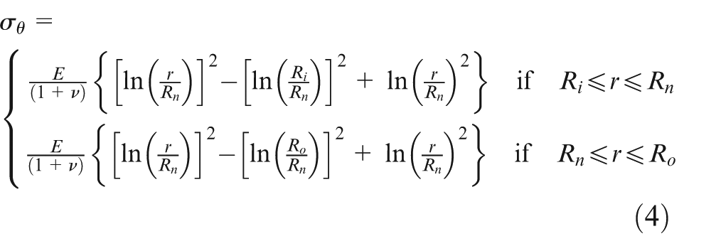
Apart from the deformation status of the sheet, the transverse stress should be continuous at neutral fiber. Therefore for an arbitrary clad sheet shown in Figure 2 considering transverse continuity, equation (5) can be found
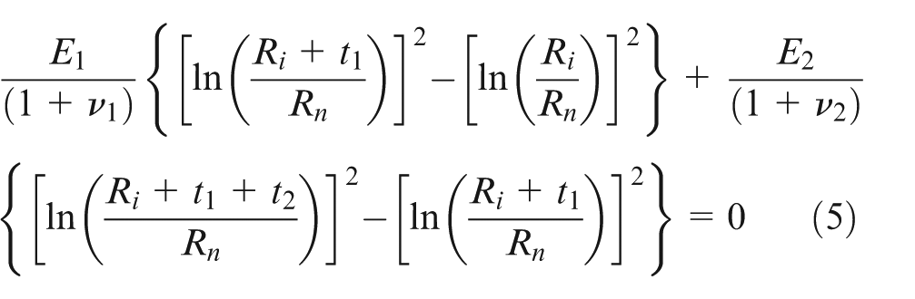
Laminated sheet bending.
In plastic state, assuming von Mises yield criterion and corresponding material flow rule, and the Holloman isotropic hardening, 30 the relations between circumferential and transverse stresses in upper and lower fibers of the neutral layer can be expressed using equation (6)
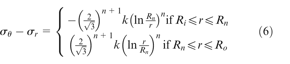
where
Substituting equation (6) in equation (1) and integration over the sheet thickness leads to equation (7) by which transverse stress distribution can be calculated in the sheet thickness during plastic deformation
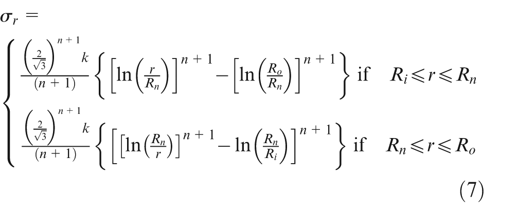
Plastic circumferential stress distribution can be calculated using equation (8) which is resulted from the combination of equations (6) and (7)
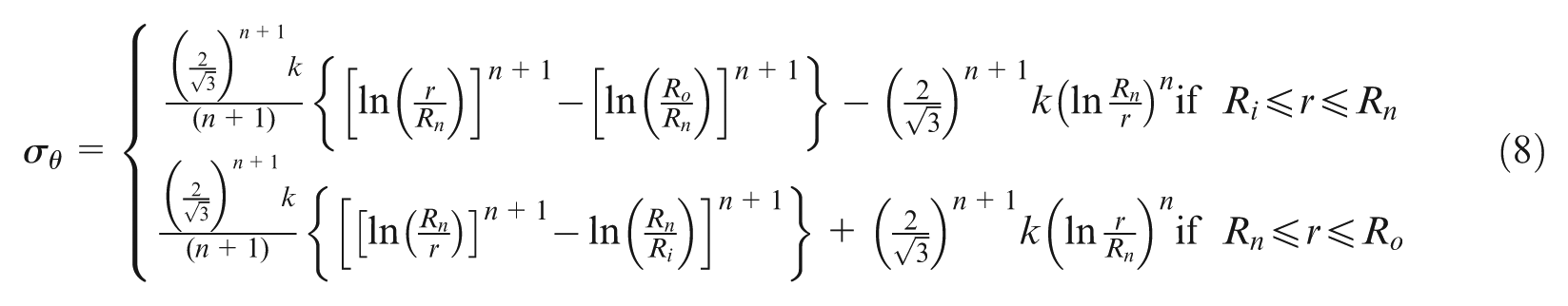
Transverse stress should be continuous at neutral fiber and bond boundary for bi-layer clad sheet as shown in Figure 2 which yields equation (9)
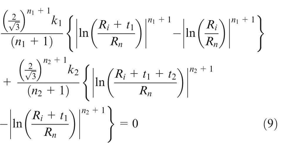
Equations (2)–(4) and (6)–(8) are derived for mono-layer sheets. These equations show that the stress distribution along the sheet length can be calculated if mechanical properties of used materials and geometrical variations of sheets are known. For a clad sheet, stress variations can be computed in the same way by noticing different material properties and thicknesses in clad layers. Equations (5) and (9), which are derived for a clad sheet, consist of three unknown parameters at forming stage, namely,
In the forming state, before unloading,
Sheet layout (a) before bending and (b) under bending.
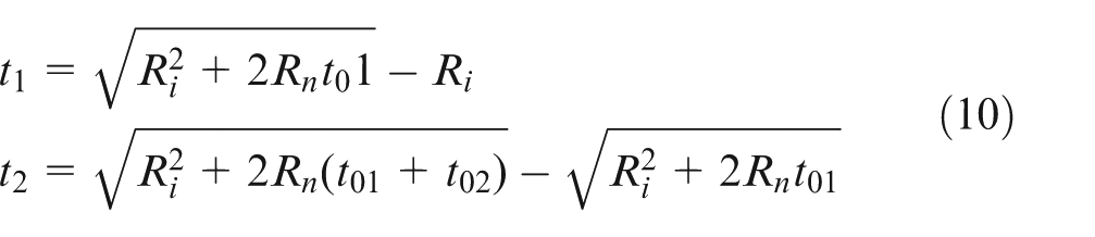
In clad sheets, thicknesses of different layers may undergo various changes in such a way that one layer may thicken and another may thin. Thickness change depends on the relative position of the layer as well as material properties of that layer, while in mono-layer sheet bending, thinning always happens. Simultaneous numerical solution of equations (9) and (10) yields the position of the neutral fiber and layers’ thicknesses. By knowing the initial thickness and material properties of each layer, stress distribution can be calculated for each layer. Knowing stress distribution along sheet thickness, bending moment can be computed.
Primary bending theory
Primary bending theory is used for elastoplastic and elastic regions. Based on Hook’s law, von Mises yield criterion and Holloman equation, elastic and plastic parts of circumferential stress in the bent sheet can be written as equation (11)
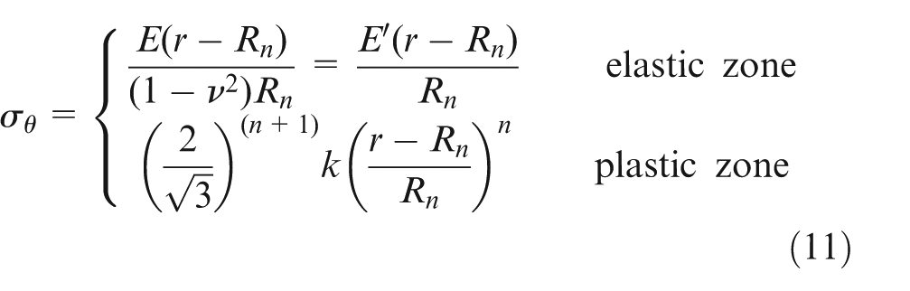
In clad sheets, generally, neutral fiber does not coincide with middle fiber due to the asymmetry and different mechanical properties of the clad layers. Thus, the position of neutral fiber should be obtained using force equilibrium equation; since there is no tension in sheet, integration of the circumferential stress in sheet thickness should be zero.
In order to calculate the bending moment, circumferential stress distribution should be found in the sheet thickness. If
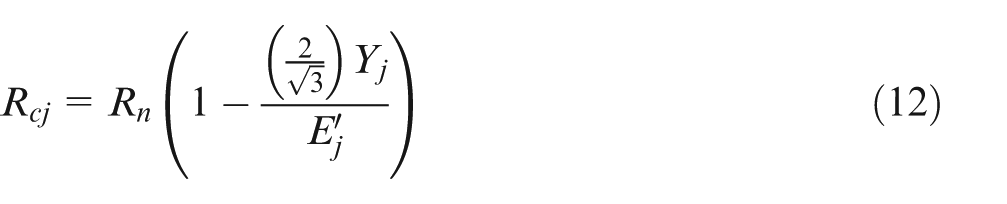
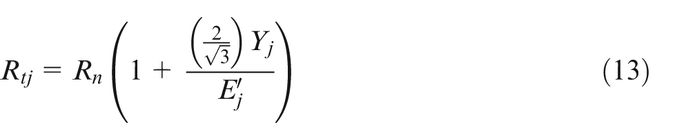
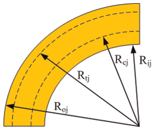
Outer, tensional yield, compressive yield and inner radii in the jth layer.
Considered
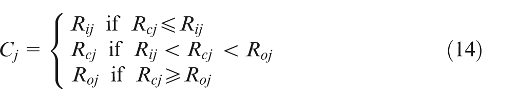
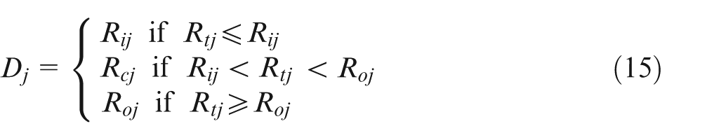
In fact,
Bending moment exerted by circumferential stress can be obtained by integrating the circumferential stress along the sheet thickness as equation (16)
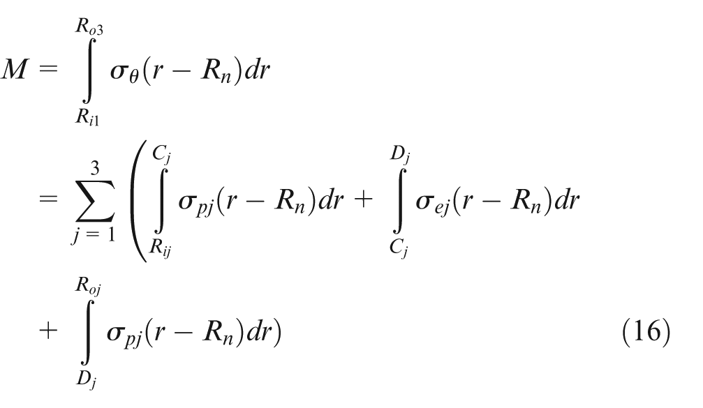
where
Air bending analytical formulation
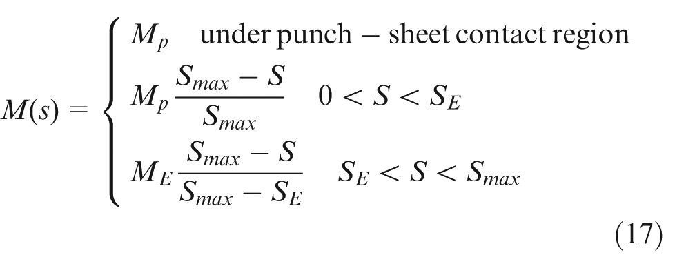
In this section, analytical formulations will be derived to calculate process parameters, namely, bending angle, contact angle, effective sheet length in die opening and springback angle. Considering Ri1 equals to punch radius Rp at the punch-sheet contact zone, maximum bending moment Mp can be calculated by integrating the circumferential stress in each layer using equation (8). Therefore, during air bending, considering linear moment distribution along sheet length, equation (17) can be presented
As can be seen from Figure 1, moment distribution along sheet length is continuous. Therefore, length of the
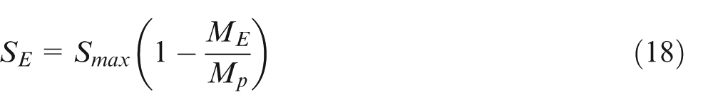
where ME is the required bending moment to yield outer sheet fiber. Amount of ME can be calculated using primary bending formulations using equations (11)–(16).
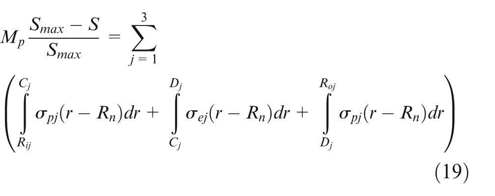
Next step is to find sheet curvature based on the location of the neutral layer in each segment of the sheet length. In the first region, where sheet contacts punch nose, sheet neutral curvature is computed using advanced bending theory using equations (9) and (10). In elastic–plastic and elastic regions, considering that in each cross section, external bending moment should equal internal bending moment, curvature distribution along sheet length can be found using equation (19)
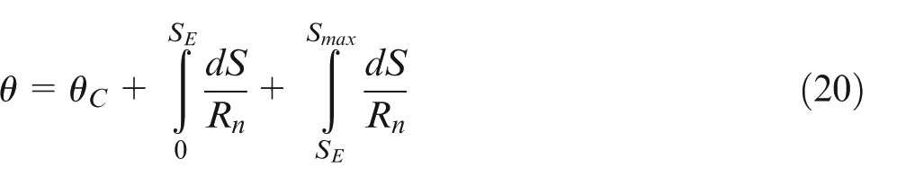
By integrating curvature distribution along sheet length, bending angle can be computed as represented by equation (20)

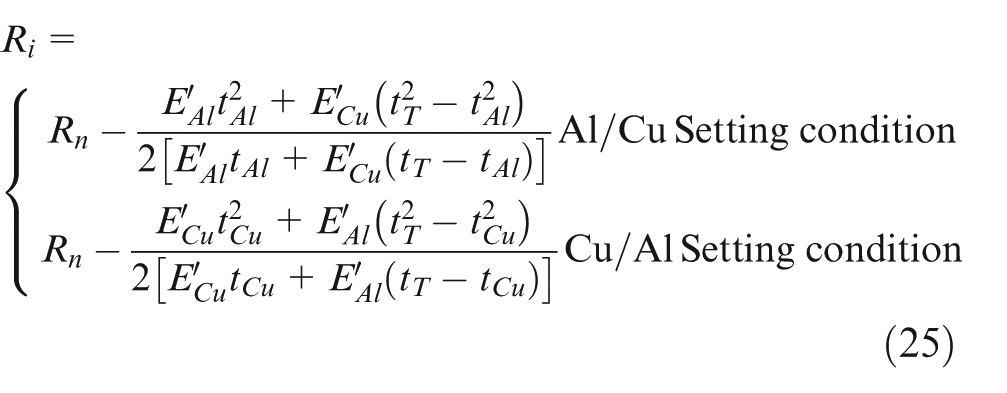
Final bending angle after unloading can be found using equation (25).
Die opening can be also related to the process parameters by using equation (26)
Springback calculation
Next step is to calculate springback after unloading, assuming pure bending is imposed on every element along the sheet length and considering springback as an elastic phenomenon. Different calculations are used to compute springback in different regions: springback calculation based on advanced bending theories for plastic region in punch-sheet contact zone, and springback calculation based on primary bending theory in elastoplastic and elastic regions along the sheet length.
For the first region in which punch nose comes to contact sheet, the springback angle is computed using equation (23)
In which neutral fibers before and after unloading are computed in the contact region using advanced bending theory. While during forming, neutral layer can be computed using equations (9) and (10), after unloading both
Algorithm to find neutral fiber before and after springback in punch-sheet contact zone.
For elastoplastic and elastic regions, first bending moment is considered to be equal to the difference of elastic moment based on equation (24)
In this equation, neutral layer and internal fiber vary along the sheet length. Thus, another equation is needed to find both. In elastic state (springback is assumed as an elastic phenomenon), it can be shown that in a bi-layer clad sheet, the distance between neutral and internal fiber remains constant. Based on force equilibrium in primary pure bending theory, one can show that the following formulation is always satisfied
Substituting this equation in equation (24) shows that bending moment distribution along sheet length is a function of one variable Rn in the range of SE < S< Smax.
Based on geometrical relation, it can be shown that differential of springback can be related to the curve length and curvature change according to equation (26)
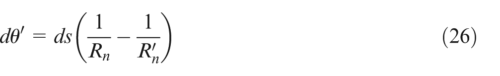
Using equations (23)–(26) and integrating equation (26) along sheet length, the second portion of the springback can be calculated. Adding up these two portions of springback yields the total springback. Process parameters, including
Applied algorithm to find springback.
FEM simulation
As mentioned before, since FEM simulation was previously performed by other researches to study springback in air bending process of clad sheets, 29 here numerical simulation is performed to evaluate theoretical predictions in terms of thickness change. Both computer-aided design (CAD) and FEM models were built using Abaqus 6.9 software package. 31 Due to the symmetry only half of the blank was modeled. The first sheet was modeled and sectioned into two layers (Al and Cu) considering no interlayer shear. Then bending tools were modeled as analytical rigid bodies. Implicit time integration FEM code was selected to simulate two-dimensional (2D) plane strain clad bending. After performing mesh sensitivity analysis, clad sheet was discretized by 11 four-node solid elements along the thickness. Bending was performed using punch radius of 4 mm and punch stroke of 12 mm. Coulomb friction model was considered with the frictional coefficient of 0.1 for sheet-die and sheet-punch contact zones.
Experimental procedure
CRB can be used for manufacturing of wide range of clad materials, and it is easy to be automated. In addition, CRB process is considered as one of the promising methods of bonding materials from initial metal sheets because of low costs.
32
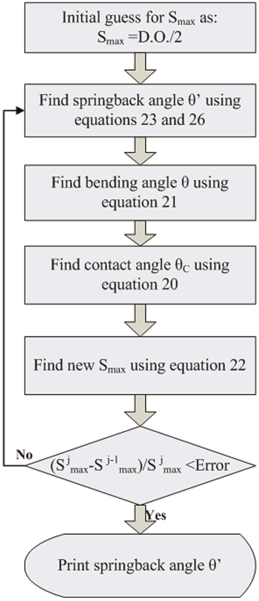
Initial 2-mm-thick aluminum and copper sheets with length of 120 mm and width of 30 mm were annealed for 1 h at 400 °c and 500 °c, respectively. After annealing surfaces of sheets scratch brushed, degreased and then cold rolled in order to produce clad sheets. Copper–-Aluminum clad sheets with total thickness of 1.1 mm were prepared for air bending tests. After rolling, clad sheets annealed in 500 °c for 30 min to create a stronger bond and annihilating residual stresses as much as possible. For evaluating mechanical properties of final clad sheet and extracting basic data for analysis, uniaxial tensile test specimens were prepared using a cutting punch according to ASTM-E8 standard. Bond strength of produced clad sheet was measured by T-peel test according to ASTM-D1876. A Santam 1195 test machine was used for performing T-peel test and uniaxial tensile test. Material properties used as inputs for analytical approach is listed in Table 1. It was assumed that materials obeyed Holloman hardening rule,
Material properties of Al-1100 and copper sheets.
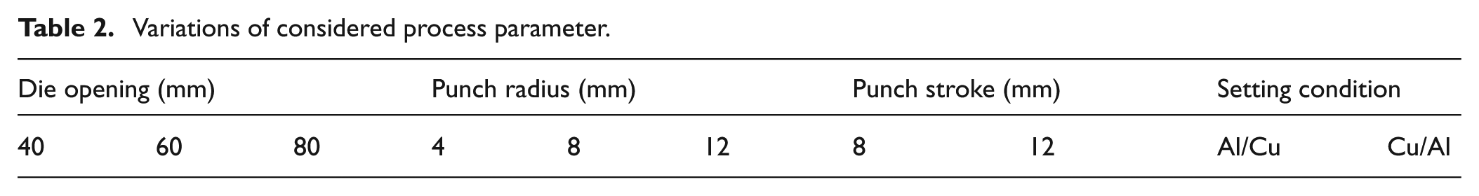
Air bending tests were carried out using nine die sets with various die openings and punch radii. Used dies in air bending tests were divided into three groups, in each group, there was same punch radius for three dies with different die openings. Using two different punch strokes of 8 and 12 mm and two setting conditions, namely, Al/Cu in which Al layer faces the punch and Cu/Al in which Cu layer faces the punch, overall 36 different air bending tests were performed to study the effect of different parameters on springback. Each set of experiments was carried on for three times to consider experimental errors. Bending tools are represented in Figure 7, and considered parameters are listed in Table 2. Bending speed was controlled in the way that no dynamic effect occurred during bending process and experiments represent a quasi-static process.
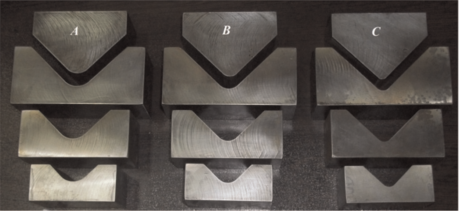
Different tool sets used for clad sheet air bending process.
Variations of considered process parameter.
Clad sheets were located on each die, and then forming process was carried out through a moving punch. Bending setup is illustrated in Figure 8. Measurements of bending angle at the end of loading and unloading stages were carried out using images captured by a digital camera. Also, it was checked from the pictures whether shear happened between layers. In all bending sets, no shear was observed to occur between layers.
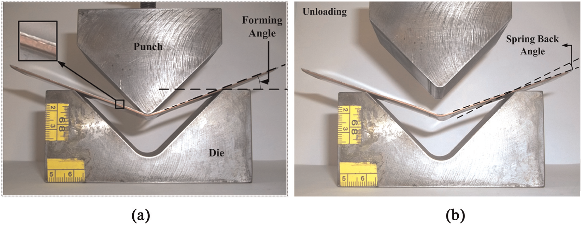
Springback measurement in experimental tests: (a) loading stage and (b) springback stage.
Result and discussion
In this section, results of analytical and experimental studies on the effect of different process parameters on springback of clad sheets are presented. Also, clad sheet thickness change is discussed. Springback data are considered for only half of the sheet. Figure 8 presents the applied method for measurement of the springback. As shown in this figure, the difference between angle of sheet with horizon in forming and after unloading is considered as springback angle.
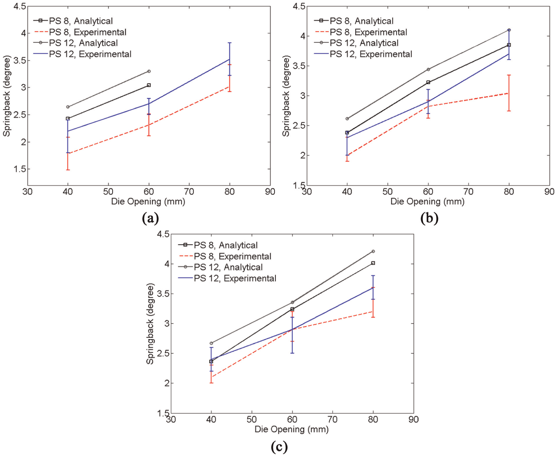
Figures 9 and 10 illustrate the effect of punch stroke and die opening on springback of clad sheets with two different Al/Cu and Cu/Al setting conditions using punch radius of 4, 8 and 12 mm. Variations in experimental data which are shown by error bars are contributed to various origins of uncertainty and lack of perfect control in experiments such as sample preparations, bending operations, method of measurements and so on. Figure 9 shows springback results of Al/Cu setting condition for different punch radii. As can be seen from this figure, springback in both analytical and experimental procedures increases with die opening. Considering springback as an elastic phenomenon, it has been previously shown that springback increases with increase in bending moment acted on the sheet. 33 With increase in die opening, higher length of the sheet undergoes bending; this leads to an increase in bending moment which consequently increases springback. For punch radius of 4 mm, analytical data are available just for die opening of 40 mm. Analytical model is based on the wrap-around assumption in which sheet’s internal bending radius equals punch radius in punch-sheet contact zone. Here, based on analytical model, no wrapping around was obtained for die openings of 60 and 80 mm when punch radius equals 4 mm, therefore, analytical formulation is not applicable to predict springback for these die sets. It can also infer from Figure 9 that with increase in punch stroke, springback increases. This observation correlates well with previous published data for mono-layer sheets. No remarkable change in springback occurred with increase in punch radius.
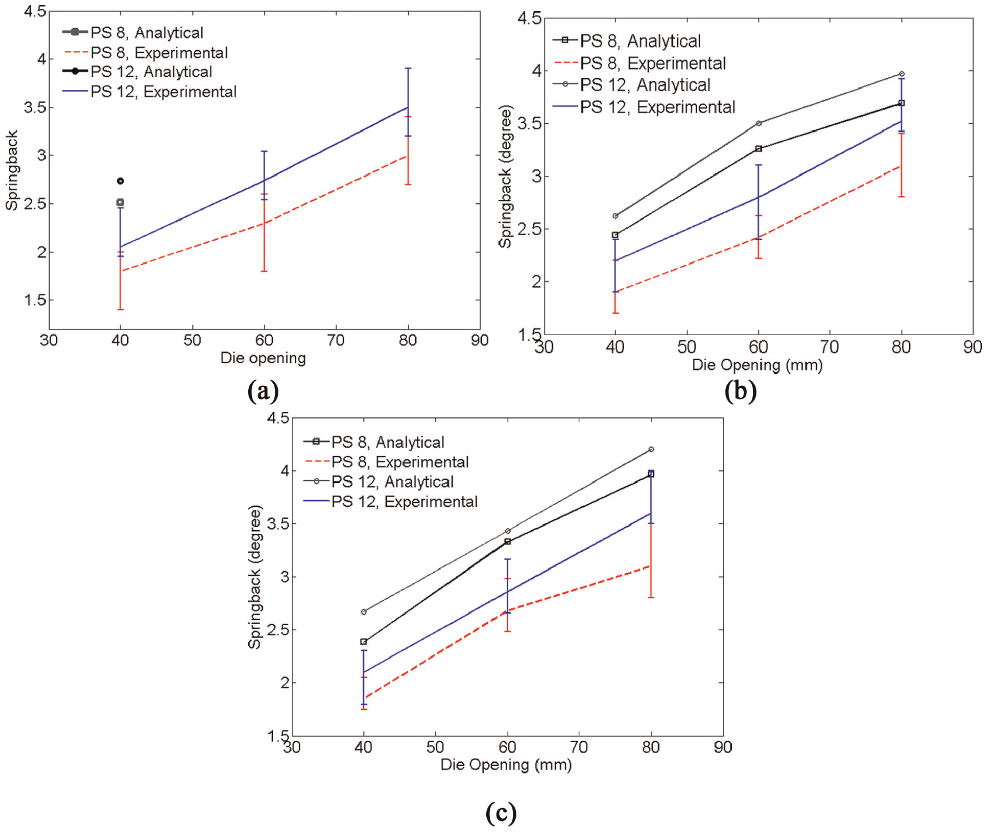
Al/Cu springback behavior with the change in die opening using analytical, numerical and experimental methods: (a) punch radius (4 mm), (b) punch radius (8 mm) and (c) punch radius (12 mm).
Cu/Al springback behavior with the change in die opening using analytical, numerical and experimental methods: (a) punch radius (4 mm), (b) punch radius (8 mm) and (c) punch radius (12 mm).
Figure 10 depicts springback results of Cu/Al setting condition. Same trend can be observed in Cu/Al setting condition in which springback increases with die opening and punch stroke. Also, punch radius has no effect on springback in selected die sets.
To study the effect of setting condition on springback, Figure 11 shows springback for both Al/Cu and Cu/Al setting conditions in different die opening when punch radius is 8 mm and punch stroke is 8 mm.
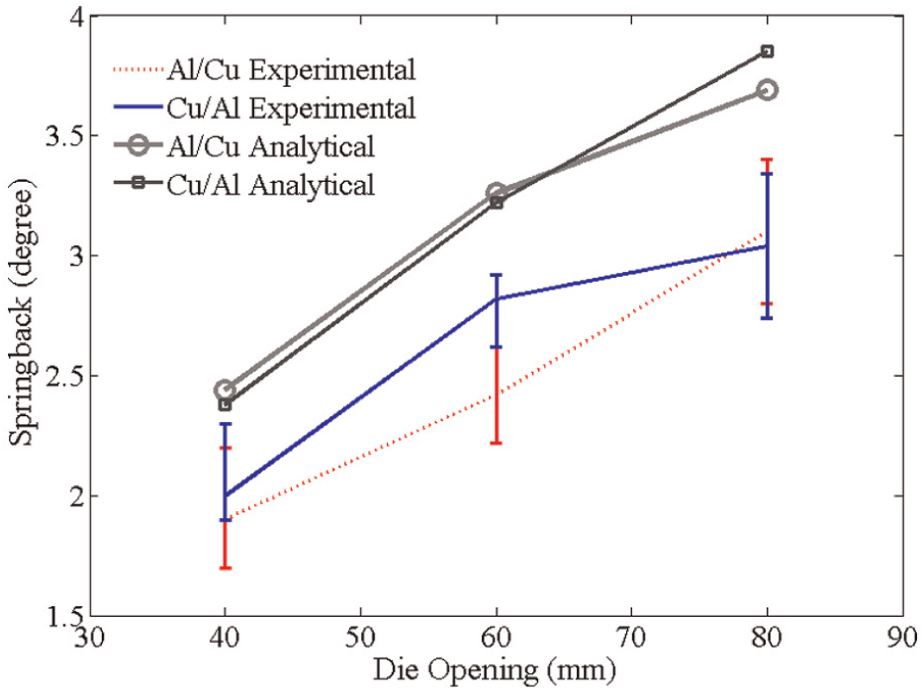
Springback for Al/Cu and Cu/Al setting conditions for different die opening when punch radius and punch stroke are 8 mm.
As can be seen from Figure 11, in both setting conditions, springback increases with increase in die opening. No difference could be observed between different setting conditions. Obtained results match well with previously reported data about clad sheet springback in air bending process. 29 Discrepancies shown in Figures 9–11 between analytical and experimental results are attributed to the non-uniformity of the sample preparation and also rooted in the material modeling of the Bauschinger effect. 29
Thickness change during forming is another important issue that limits the amount of bendability. In mono-layer sheet bending, thickness thinning happens, while in clad sheets, due to different material properties and relative position in bending, there could be either thinning or thickening. 29 Based on advanced bending theory in the punch contact zone, thickness variations for each layer were computed for different punch radii. Figure 12 demonstrates the thickness change for each layer in different setting conditions using analytical approach. Overall thickness change is also compared using analytical and experimental methods in Figure 13.
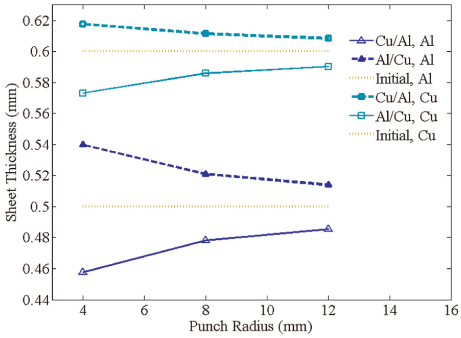
Thickness change in each of Al and Cu layers in different setting conditions for different punch radii.
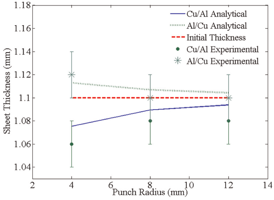
Overall thickness change in clad sheets in different setting conditions for different punch radii.
As can be seen from Figure 12, depending on the setting condition, Al and Cu layers may undergo thinning or thickening. Initial thickness of the Al and Cu layers equal 0.5 and 0.6 mm, respectively. In Cu/Al setting condition in which Cu faces the punch nose, thickening occurs in the Cu layer, while thinning happens in the Al layer. On the contrary, in Al/Cu setting condition, thickening and thinning occur for Al and Cu layers, respectively. Apart from the setting condition, thickness change in the Al layer is much more than that in the Cu layer due to differences in their properties. It can be observed from Figure 13 that overall change in thickness dramatically differs with setting condition. In Cu/Al condition, the overall sheet thickness is less than its initial amount in all punch radii. In the other hand, sheet thickening happens in all bending radii for Al/Cu setting condition. This observation correlates well with previous findings where in the setting condition in which softer layer faces the punch, the total thickness thickens and vice versa when harder layer faces the punch, total thickness thins. 29 Another important observation in Figure 13 is that the change (thinning or thickening) in sheet thickness decreases with punch radius. This also matches well with previous reports. 29 To clarify different thickness behaviors in different setting conditions, circumferential stresses in both setting conditions are depicted in Figure 14 using analytical method when punch radius equals 4 mm.
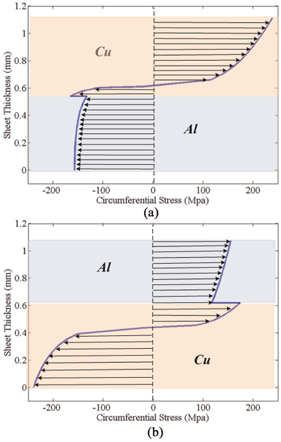
Circumferential stress distribution for (a) Cu/Al and (b) Al/Cu setting conditions with punch radius of 4 mm.
Based on Figure 14, the Cu layer undergoes much more stress in both setting conditions. In both settings, the neutral layer coincides with the Cu layer. In Al/Cu arrangement, it places at the 0.65 mm distance of the punch, while in Cu/Al arrangement, it locates 0.45 mm from the punch. This attributes to different thickness change behaviors in these setting conditions.
To better understand this force distribution in each layer, exerted forces are considered for different setting conditions. Force per unit of the width from analytical approach is calculated based on the stress distribution in the thickness using numerical integration. By dividing sheet thickness into 40 segments and applying trapezoidal integration, net force for each of the layer in different settings is computed as is shown in Figure 15.
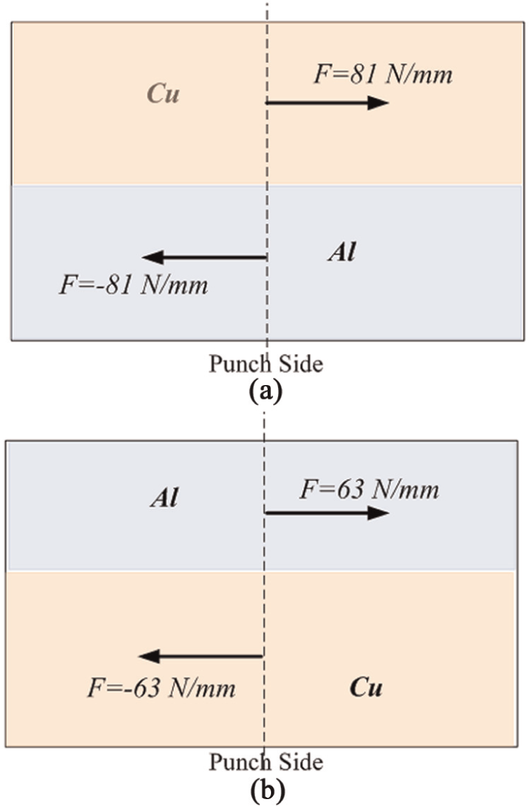
Net force acting on each Al and Cu layer in (a) Cu/Al and (b) Al/Cu setting conditions with punch radius of 4 mm.
As can be seen from Figure 15 in both setting conditions, total net force acting on the thickness equals zero. This confirms the assumption of pure bending in analytical formulations in which no total force is applied on the sheet thickness. However, considering each layer individually, differences appear in Cu/Al and Al/Cu setting conditions where change in each layer’s force is about 28%. In Cu/Al setting condition, each layer undergoes about 63 N/mm. This force has less ability to change thickness of the sheet comparing to 81 N/mm which is imposed on each layer in Cu/Al setting condition. Furthermore, considering different material properties of the Al and Cu layers, 28% change in exposing force has less effect on thickness change for Cu layer than that for Al layer. Therefore, Al/Cu setting condition attributes to sheet thickening. From another view as discussed in Figure 14, in Cu/Al setting condition, only about 40% of the total sheet is in compression which is probable to boost the thickening and about 60% of the sheet thickness is in tension which increases the thinning. Opposite state governs the Al/Cu setting condition in which 60% of the sheet is in compression and 40% is in tension. Thus, in Cu/Al setting condition total thickness decreases and in Al/Cu setting condition total thickness increases.
Figure 16 shows FEM results of thickness change in clad air bending with punch radius of 4 mm and die opening of 40 mm. Punch stroke was chosen to be 12 mm to guarantee that sheet would wrap around the punch and FEM results is comparable with analytical ones. Comparing Figure 16 with its own analytical counterparts (Figures 14 and 15) shows good correlation between analytical and FEM models. First, the stress distribution is matched within sheet thickness. Furthermore, to compare analytical and numerical results using nodal stress and a numerical integration applying trapezoidal method, net force for each layer is calculated. Comparing FEM results with analytical results show discrepancy less than 10%.
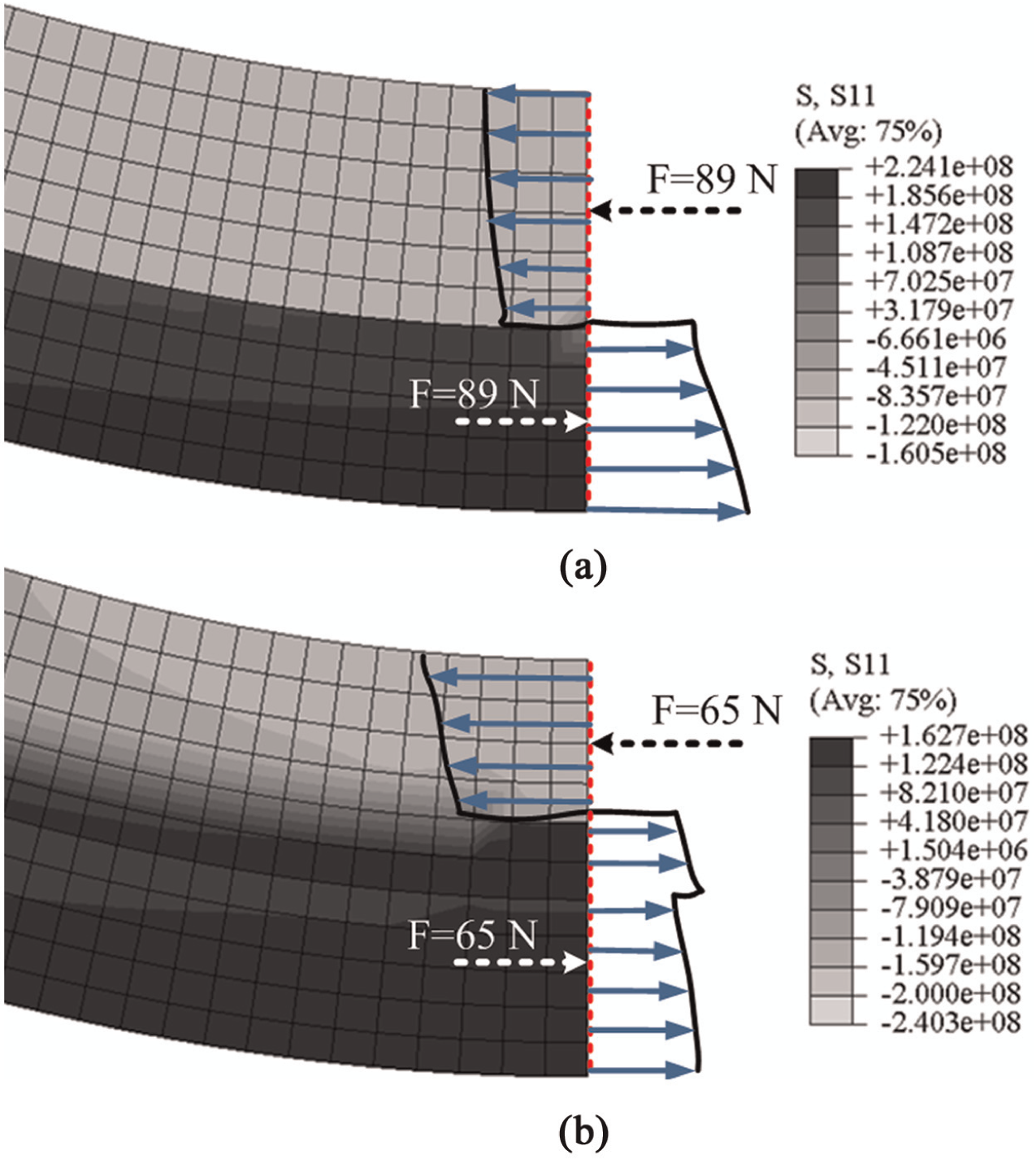
Numerical results of circumferential stress distribution and resultant force in each layer for (a) Cu/Al and (b) Al/Cu setting conditions in clad air bending process.
Conclusion
In this article, effects of different bending parameters on springback of Al/Cu clad sheets are presented for air bending process using analytical and experimental procedures. Die opening, punch stroke and punch radius and different setting conditions were investigated. Analytical model was developed based on the combination of advanced and primary bending theories. In the analytical model, it was assumed that sheet would wrap around the punch in punch-sheet contact zone. Experimental tests were also followed using different bending sets to verify analytical results. Also, thickness change in different setting conditions was analytically predicted using advanced bending formulation and later verified with numerical and experimental results. Following findings can be highlighted:
With increase in die opening, springback increases. Die opening is the most effective parameter on springback.
Increasing punch stroke leads to increase in springback.
Punch radius has no influence on springback in different die sets.
Different Al/Cu and Cu/Al setting conditions have no remarkable influence on springback.
The angle in which wrapping around starts is affected by punch radius, die opening and setting condition. With increase in punch radius, sheet tends to wrap around the punch in the earlier bending angle, while with increase in die opening, wrapping around starts in larger bending angles. In a certain die set, Cu/Al setting condition leads to an earlier wrapping around.
Setting condition remarkably influences the thickness change in the bent clad. In this case, if Cu faces the punch, the overall thinning happens, while clad sheet thickens if Al faces the punch.
Footnotes
Appendix 1
Declaration of conflicting interests
The authors declare that there is no conflict of interest.
Funding
This research received no specific grant from any funding agency in the public, commercial, or not-for-profit sectors.