
Abstract
AC-170PX (AA6014) alloys are typically used in lightweight automobile vehicles. Laser welding can be a viable tool for the assembly of components. However, porosity is often generated during aluminium welding. In this article, an investigation is reported on the characteristics of porosity formation in high-power disc laser welding of AC-170PX aluminium alloy sheets in two weld joint configurations: fillet edge and flange couch with three different filler wires of 4xxx, 3xxx and 5xxx aluminium series for each joint. Porosity, microstructures, tensile strengths and joint geometry were investigated. It has been found that the use of filler wires with higher Mg and Mn content such as AA5083 and AA3004 leads to a significant reduction in porosity to less than 1.5% in both types of joints compared with up to 80% porosity with the silicon-rich AA4043 wire. The mechanism that led to this improvement is discussed.
Introduction
Aluminium alloys are becoming commonly used in rail vehicles, electronics, automotive and aerospace industries due to their high-strength-to-weight ratio. Different welding techniques such as friction stir welding and arc welding have been successfully applied for jointing components.1–3 Laser welding would enable several advantages over the conventional welding techniques. These advantages include higher welding speed, higher precision and more flexibility. 4 However, laser welding of aluminium alloys can be challenging due to defects associated with melting, solidification, shrinkage, thermal expansion, hydrogen trapping and other gases’ solubility5,6 and so on. The type and amount of defects depend on the chemical compositions of the parent materials and the filler wires as well as welding parameters. Porosity and cracks are the most common defects that are observed during aluminium alloys’ welding. Some investigations reported crack initiations during welding of aluminium alloys (6xxx series) that have a wide solidification range between the liquidus and the solidus, while others reported porosity generation in aluminium alloys with high magnesium content. This was attributed to the lower melting temperature of Mg compared to Al.7,8 Haboudou et al. 9 used different methods for porosity reduction such as surface preparation including sand blasting, polishing and laser cleaning, as well as dual spot laser welding. Their experiments showed that surface cleaning reduced porosity in the weld and laser cleaning had the most significant effect among other cleaning techniques. Moreover, the increase in the interaction time between the laser beam and the metal using dual spot beams led to a reduction in porosity by about 8% for AA5083 and A356 alloys. Similar trend has been observed by Blackburn et al.,10,11 who not only investigated the effect of twin spot laser beams on pore reduction in titanium alloys but also optimised the directed assist gas parameters to achieve the same goal. The directed argon gas jet led to less porosity, deeper penetration and eliminated other weld defects such as undercuts and spatter. AlShaer et al. conducted an investigation on porosity reduction using laser cleaning as a surface preparation method prior to laser welding of Al alloys for automotive applications. They used Nd:YAG nanosecond pulsed laser to clean the alloys before being welded using a 5-kW disc laser. Their findings indicated that laser cleaning has eliminated all contaminants and dry lubrication from the surface of AA6014 alloys and led to a significant reduction in porosity to less than 1% for fillet edge and flange couch joints. 12
Although much attention has been drawn to porosity formation in laser welding of aluminium alloys, few investigations concentrated on the effect of the filler wire properties on weld defects. The influence of shielding gases and their delivery in laser welding of aluminium alloys were reported by Ancona et al. 13 and Katayamaand colleagues.14,15 who indicated that the use of helium gas achieved deeper penetration than both Ar and nitrogen gases due to the reduction in plasma. The influence of different filler wires on Nd:YAG laser welding of dissimilar materials was reported by Pinto et al., 6 including welding of AA6061-to-LM25, AA6063-to-AA6083 and AA6060-to-AA5754 using 4000 and 5000 series filler wires. Their findings concluded that AA4047 filler wire is the most suitable for welding 5000-to-6000 aluminium alloys due to its high silicon content if a suitable shielding gas is used. A 5xxx series filler wire causes hot cracking in dissimilar 5000-to-6000 laser welding. Welding different materials with different chemical compositions using filler wires that have another chemical composition make it difficult to observe the effect of the filler wire composition on porosity formation in the welds. To the authors’ knowledge, no investigation has been reported on the effect of filler wires on porosity formation in laser welding of AC170-PX (AA6014) alloy.
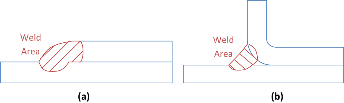
In this investigation, AC-170PX (AA6014) aluminium alloy sheets were laser welded using three different filler wire types to examine their influence on porosity formation. AC-170PX aluminium alloys are typically used for automotive applications due to its high-strength-to-weight ratio and corrosion resistance. Two types of joints were welded using a high-power disc laser and the quality of the welds was evaluated for different filler wires. Figure 1 illustrates the joint configurations.
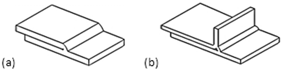
Two types of joint configurations used in this investigation: (a) fillet edge and (b) flange couch joint configuration.
Materials and experimental procedure
Chemical compositions of the parent material and the filler wires are given in Table 1. Sheets of 1.1 mm thickness were used as the parent material. In this investigation, the aluminium alloy sheets were welded using different filler wires of 1.2 mm diameter: AlSi5 (AA4043), AlSi12 (AA4047), AlMgMn (AA3004) and AlMg4,5Mn (AA5083). In each type of welds (fillet edge and flange couch), the three types of filler wires were compared. The base material AC-170PX (AA6014) is tempered to T4 and coated with titanium and zirconium (4 mg/m2) and lubricated using dry lubricant AlO70 (1.5 g/m2) as part of the material forming process. The mechanical, physical and microstructural properties after laser welding were characterised in the transverse direction of rolling according to EW 10002. The physical and mechanical properties of the alloys are given in Table 2.
A TruDisk 5302 (max. power 5300 W) disc laser with a Scansonic AlO3 head was used for welding the sheets. Table 3 and Figure 2 give the laser technical specifications and the schematic of the laser head, respectively. A lens with focal length of 176 mm was used to focus the beam at 10 mm below the workpiece surface producing a spot size of 600 µm at focus. The use of a defocused laser beam for the welding process is to compensate for the effect of thermal lensing (that would effectively shorten the focal length to move the focal position closer to the lens) and to provide sufficient heating area for the weld zone formation. Argon gas was used for shielding the weld zones with a flow rate of 15 L/min. Argon is widely used in industry as a shielding gas for the weld zone protection from oxidation since it is cheaper and heavier than helium. 19 A length of 300 mm weld seam was produced for each experimental combination using a drag angle of 10° and a lateral angle of 45°. An inclined beam was used in laser welding of aluminium to prevent beam interaction with plasma and to avoid back reflection and the optics damage. Inclined gas shroud removes the plume and prevents its interaction with the beam. Figure 3 demonstrates these angles in the weld configuration. Ultimate tensile strength (UTS) was measured for all samples using Galbadini Quasar 100 kN test machine. (Samples were prepared according to ISO 6892-1 2009.)
TruDisk 5302 laser unit technical properties. 20
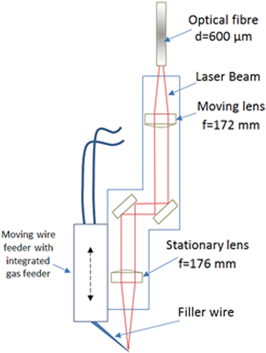
Scansonic AlO3 laser head.
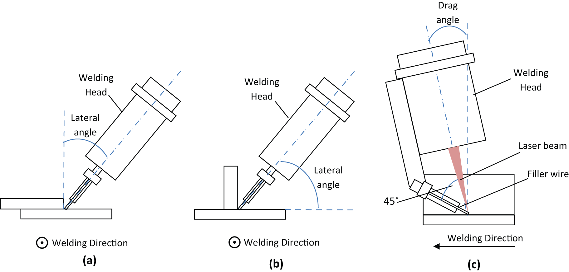
Lateral angle for the (a) fillet edge joint and (b) flange couch joints, respectively; (c) the drag angle for both types of joints.
The wire feeding rates were selected in the range of 3.1–5.7 m/min to provide sufficient but not excessive filler material in the weld zone. This allows welding under different laser line energy inputs that would bond the two sheets to meet the industrial joint geometry specification (e.g. weld depth and width).
On one hand, the increase in silicon content in aluminium alloys increases the fluidity since the heat of fusion of primary silicon is higher by 4.5 times than that of pure aluminium. Hence, liquid AlSi12 alloys are less viscous than molten AlSi5 and Al–Mg alloys.21,22 On the other hand, Al–Mg wires produce more spatter and ‘smut’ (black deposit of the metal oxide on the weld surface) than Al–Si wires which is very detrimental to the appearance of the welds in the structural components. 23 Accordingly, limits for wire feeding rates apply when Al–Mg fillers are used for such applications. Therefore, identical feeding rates cannot be used for all cases regardless of the wire composition. For each wire, their feed rates were selected to achieve optimum welds.
To compare the effect of filler wires, the laser welding parameters were fixed in each set of welding experiments at 35–50 mm/s welding speed at a laser power of 3500–5300 W. The selection of laser powers and welding speeds was to provide the required line energy (approximately 100 J/mm) to melt the wire and some surrounding material. On the other hand, welding parameters were selected to meet the industrial requirements requested and to be in the range that is utilised and feasible for automotive industry.
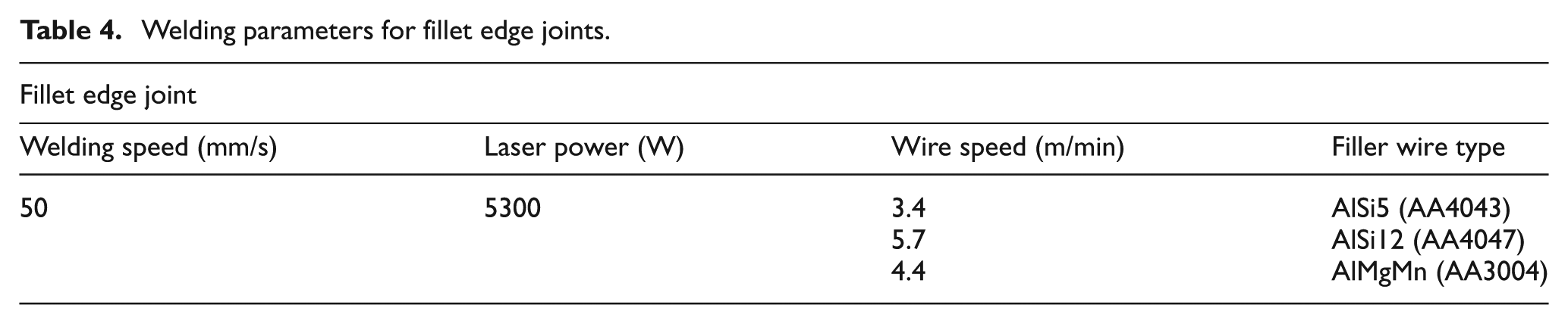
After welding had been completed, all samples were sectioned in the perpendicular direction to the weld axis, and then ground using abrasive papers that contain silicon carbide particles. Grinding was performed in five stages using 80, 300, 600, 1200 and 4000 grit papers using a rotating disc (Mecatech 334). Following that, the samples were polished using 3 and 1 µm diamond pastes on a rotating cloth. The samples were then etched using sodium hydroxide solution (1 g NaOH + 100 mL H2O) in which they were immersed for 45 s. The microstructure and the dimensions of the welds were then examined using a digital microscope KEYENCE VHX-500F. It is worth mentioning that porosity levels were determined using cross sections along the weld bead and all measurements were repeated multiple times. Three cross sections were made for the weld bead and porosity content was calculated as a ratio of the pores’ projected area to the weld cross-sectional area. The measurements of porosity content for each section were then repeated three times. The errors shown in Figure 10 demonstrate the level of deviation in these measurements. The same procedure was also followed for flange couch joints, and the parameters used in welding the fillet welds are shown in Table 4.
Welding parameters for fillet edge joints.
Experimental results
Fillet edge joints
Microstructure and porosity characteristics
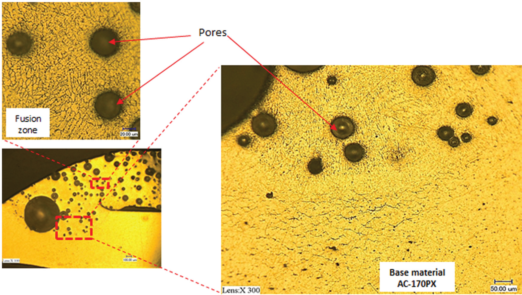
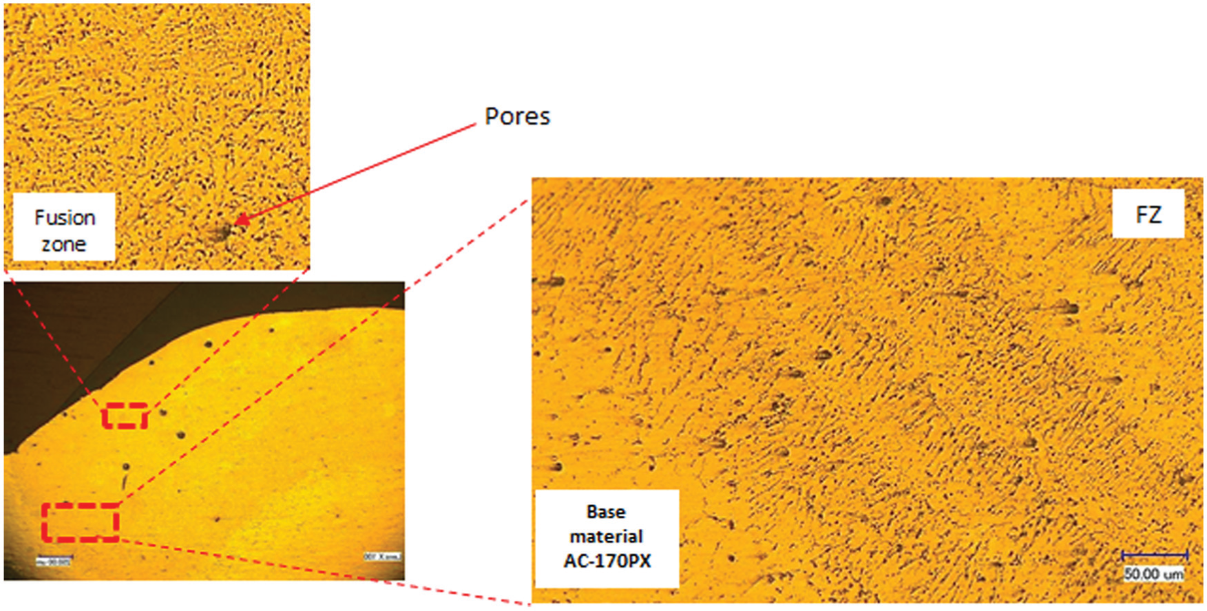
Micro-sections were examined initially using low-magnification optical microscopy (×100) and porosity levels and other defects were examined. Figure 4 shows the microsections of the fillet edge samples welded using different filler wires.
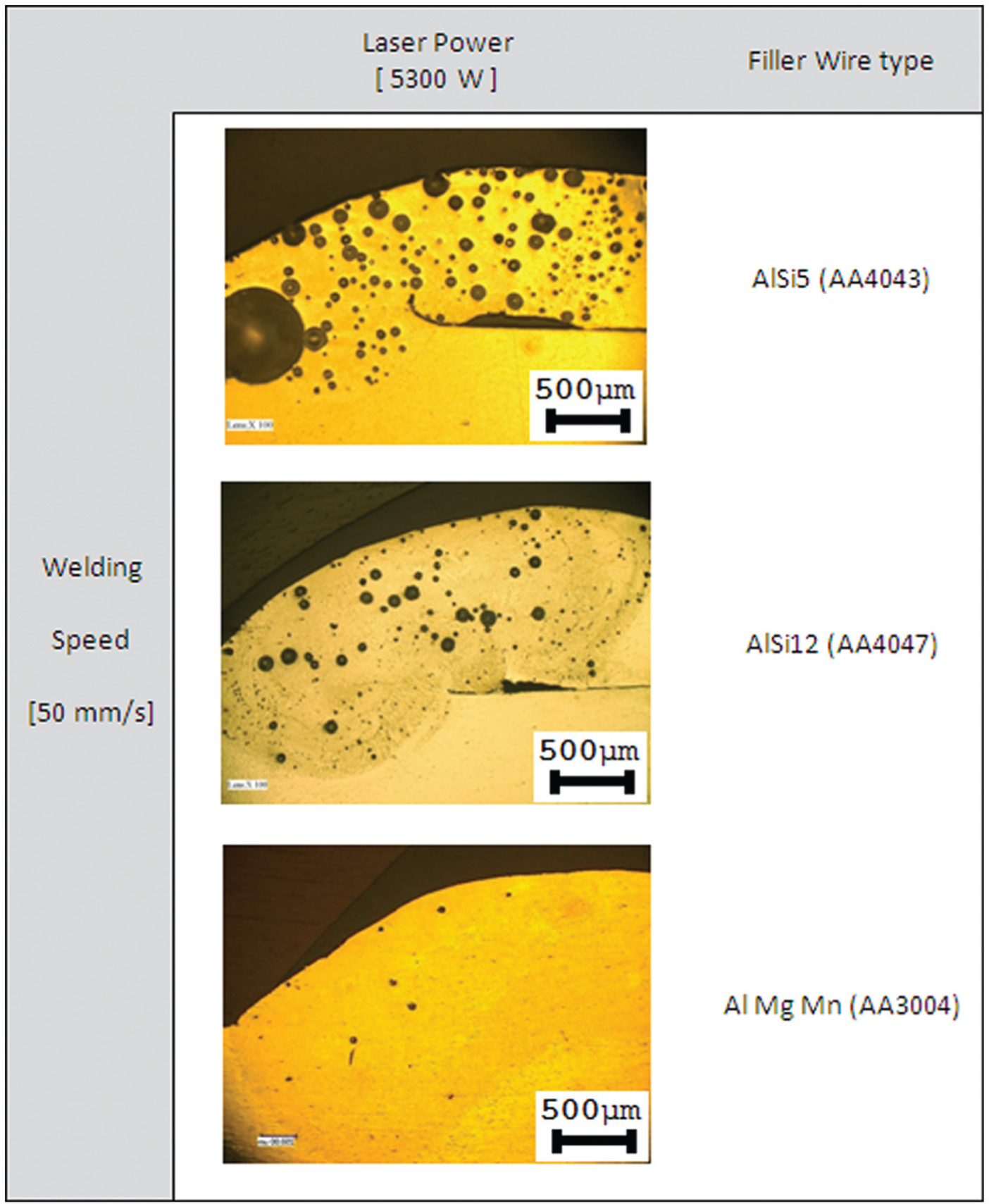
Microsections of the fillet edge joins welded using different filler wires.
From Figure 4, it can be seen that a large quantity of porosity is observed during welding using the AlSi5 filler at the specified parameters. However, less porosity was seen when welding with AlSi12 filler and it was further reduced with the AA3004 filler. Some cracks were also observed with the AA4043 (AlSi5) filler wire welds especially at the root of the joints but no macro- or micro cracks were observed in the weld joints welded with AlSi12 and AA3004 wires. Moreover, both AlSi5 and AlSi12 welds suffered from the lack of fusion at the weld root while no such defect exists in the AlMgMn (AA3004) welds.
Using higher magnification (×400), the welds’ microstructure can be clearly examined. Figure 5 shows the microstructure in the fusion zone (FZ), heat-affected zone (HAZ) and the parent material after welding using the AlSi5 filler wire. The microstructure of the base material consists of elongated aluminium grains whose boundaries do not appear clearly due to the large elongation occurred during rolling process. Black dots of magnesium silicide Mg2Si particles can be seen distributed randomly within the grains. In the HAZ, Mg2Si is rearranged to form a eutectic phase and precipitates at the grain boundaries in a dendritic form.
Microstructure of the weld–HAZ–base material of a fillet edge joint welded at 5300 W laser power and 50 mm/s welding speed (AlSi5 filler wire).
In the FZ, Mg content in the filler wire is very low in comparison with the silicon content. Therefore, aluminium forms a (Al–Si) eutectic with silicon and settles at the grain boundaries. The magnesium silicide is not clearly observed in this region due to the low Mg content in comparison with the parent material.
Figure 6 shows the microstructure of fillet joints welded using the AlSi12 filler wire. The microstructure in the AlSi12 weld is similar to that of ALSi5 in terms of the phases. However, due to the high silicon content in the AlSi12 (4047) filler wire, dendritic Al–Si eutectic becomes coarser and more visible in between the Al grains and it looks like a crack under the microscope using low magnifications. Pores of different sizes appear clearly in Figure 6 in the FZ.
Microstructure for a fillet edge joint welded using AlSi12 filler wire.
Figure 7 shows the difference in Al–Si amount in the FZ for both AlSi5 and AlSi12 filler wire. It can be seen that the grain size in the case of AlSi12 ranges between 5 and 7 µm, compared with 10 and 15 µm in the AlSi5 welds.
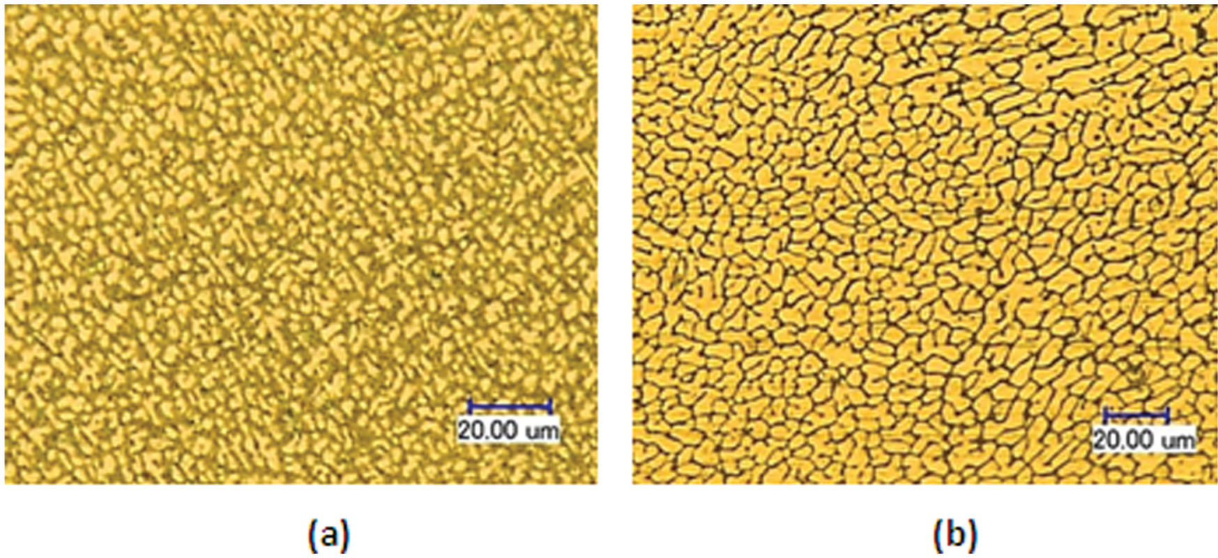
Microstructure comparison between fillet edge joints welded using (a) AlSi12 filler wire and (b) AlSi5 filler wire.
The microstructure of weld with the AlMgMn filler wire is shown in Figure 8. The HAZ takes a different appearance in which Al solid solution appears in the light yellow zone containing some coarse and fine particles. Since the filler wire and the base materials are of different chemical compositions mixed together, the black particles that appear in between the grains boundaries in the HAZ can be Mg2Si which originates from the base material and the eutectic Al6Mn is formed due to the high manganese content in this filler wire in comparison with AlSi5 and AlSi12 fillers. In the FZ, randomly distributed dark particles of FeAl3 eutectic and Al6Mn are observed within the aluminium solid solution with light colour. FeAl3 becomes more pronounced in the FZ because AA3004 filler wire contains two times more iron than the base material. 24
Microstructure of the weld–HAZ–base material of a fillet edge joint welded at 5.3 kW and 50 mm/s (AlMgMn filler wire).
It is obvious from Figure 4 that porosity reached significant proportions for the welds with silicon-rich filler wires, while very little pores were detected for welds with Mg-rich filler wires. Porosity was estimated as the ratio of the pores’ projected area to the weld cross-sectional area averaged in multiple cross sections. Pores and weld areas were determined directly using the microscope image processing software.
Figures 9 and 10 illustrate the weld areas for both types of joints where porosity was characterised, and porosity percentages for the three different filler wires, respectively. Porosity content in the AlSi5 welds has reached up to 80% at the specified weld parameters. It was reduced to less than 10% for the AlSi12 to reach only 1.4% for AlMgMn welds. The maximum pore diameter observed in the fillet edge joints reached up to 690 µm for the AlSi5, 90 µm for AlSi12 and 56 µm for AlMgMn welds.
Weld cross-sectional area used in porosity proportions determination for (a) fillet edge and (b) flange couch joints.
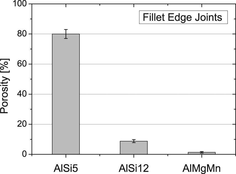
Porosity content in fillet edge joints welded with different filler wires at 5.3 kW and 50 mm/s.
Weld dimensions and tensile strength
The weld penetration depth and weld width definition for fillet edge joints are illustrated in Figure 11.
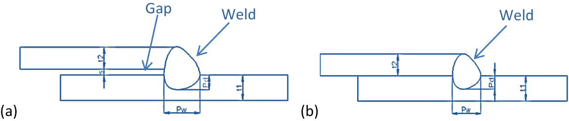
Fillet edge weld dimensions: (a) fillet weld with gap between the sheets and (b) fillet weld with no gap.t 1 and t2 are the sheets’ thicknesses, s is the gap size, Pw is the weld width and Pd is the penetration depth.
The weld dimensions were measured using the optical microscope for all the joints as shown in Figure 12. All weld dimensions were found to be the maximum when AlMgMn was used as filler, since the penetration depth and the weld width reached up to 1000 and 2500 µm, respectively. Penetration depth for the welds using either AlSi5 or AlSi12 wires was approximately half that for AlMgMn. This difference in weld dimensions, although welding parameters were the same, can be attributed to the root cracks that caused the lack of fusion for both AlSi5 and AlSi12 fillers.
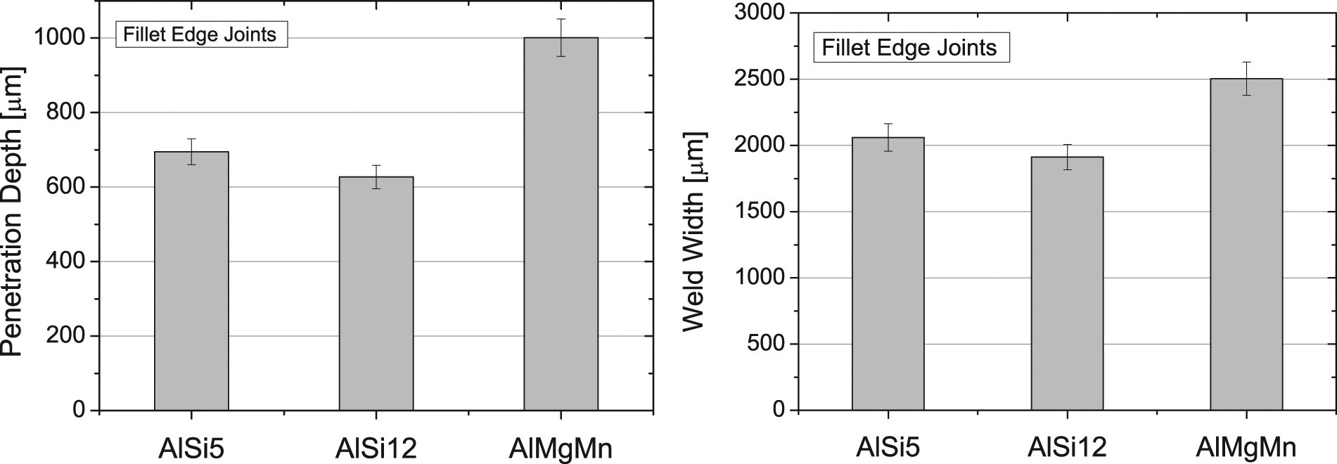
Weld dimensions for fillet edge joints using various filler wires at 5.3 kW and 50 mm/s.
The difference in the weld dimensions and porosity content besides the difference in the chemical composition of the filler wires led to a difference in the UTSs. As shown in Figure 13, the UTS has increased from its minimum value for AlSi5 (38%) to the maximum value for the AlMgMn (55%) weld. Although AlSi12 weld dimensions were less than those obtained for the AlSi5 welds, porosity caused a significant reduction in the UTS of the AlSi5 welds since it occupied 80% of the weld cross-sectional area. The use of AlMgMn filler achieved the maximum UTS due to three reasons: the low porosity content in the weld, lager FZ volume and the high Mg and Mn content that is responsible for increasing the strength. 25
Tensile strength for various filler wires’ welds at 5.3 kW and 50 mm/s as a proportion of the base material UTS (195 MPa).
Flange couch joints
Microstructure and porosity characteristics
The same analytical procedures were followed for the flange couch joints, and the welding parameters are given in Table 5. Figure 14 shows the micro-sections of flange couch joints welded using AlSi5, AlSi12 and AlMg4,5Mn filler wires at 3500 W laser power and 35 mm/s welding speed.
Welding parameters for flange couch joints.
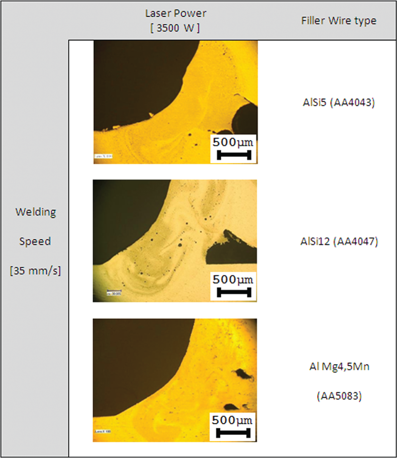
Microsections of flange couch joints welded using different filler wires.
Figure 14 shows that the use of AlSi12 (AA4047) wire increases porosity in comparison with AlSi5 (AA4043) filler at the same operating parameters. AlMg4,5Mn (AA5083) reduced porosity in the flange welds significantly in comparison with other fillers. Micro-cracks were not observed in any of the joints and welds did not suffer from other defects such as lack of fusion or undercuts.
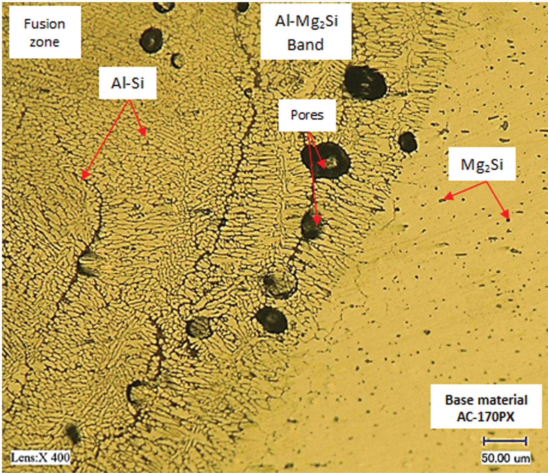
The microstructure of the flange couch welds was found to be identical to that shown in Figures 5 and 6 when AlSi5 and AlSi12 wires were used, respectively. This can be related to the fact that the same filler wires were used to weld the same type of the parent material. Therefore, the joint configuration did not have any effect on the type of phases existing in the flange welds. A different microstructure is observed in Figure 15 due to the use of AA5083 filler wire. In the HAZ, black dendrites of magnesium silicide that originates from the base material are pronounced at the grains’ boundaries since this region contains relatively high silicon content. Beside this phase, FeAl3 phase is observed as dark rounded dots that are distributed randomly over the HAZ. In the FZ, FeAl3 becomes more evident since higher iron content exists in the FZ than in the HAZ. This phase is distributed within a light gray network of Mg2Al3 eutectic which is formed from the very high magnesium content in AA5083 alloy,24,26 Small pores can also be seen within different zones.
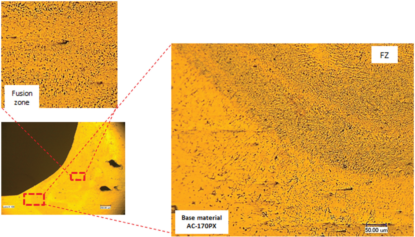
Microstructure of the weld–HAZ–base material of a flange couch joint welded at a 3500 W laser power and a 35 mm/s welding speed (AlMg4,5Mn filler wire).
After calculating porosity percentages, Figure 16 is created to compare the different flange welds. It can be seen from this figure that porosity recorded the highest value for AlSi12 (AA4047) welds while the minimum value was achieved in AlMg4,5Mn (AA5083) welds. At this level of power and welding speed, although the joint configuration helps the gases to escape from the welding pool, more pores were generated in AA4047 flange joints. The high silicon content (about 12%) of the AA4047 wire increases fluidity and hence the speed of the flow inside welding pool, which, in turn, promotes the interaction between liquid aluminium and ambient gases especially shielding gases that are blown directly at high flow rate (15 L/min) onto the welding pool. Another source for porosity during laser welding of aluminium alloys can be the hydrogen gas. Some works reported that hydrogen was the main reason for porosity formation and even 2 ppm of hydrogen can still lead to porosity in aluminium welds. 27
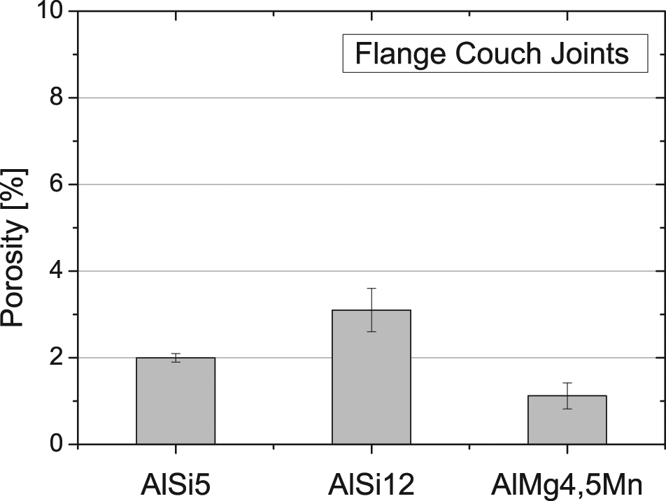
Porosity content in the flange couch joints welded with different filler wires at 3.5 kW laser power and 35 mm/s welding speed.
Moreover, some pores can be formed due to the keyhole instability which is dependent on how stable the flow inside the welding pool is. Higher fluidity may increase the chance to keyhole collapse and leads to more porosity.7,28,29 The maximum pore size observed for the flange couch joints in this investigation was about 65 µm in diameter for both AlSi5 and AlSi12 welds and 22 µm for AlMg4,5Mn welds.
Weld dimensions and tensile strength
The weld penetration depth and weld width for flange couch joints are illustrated in Figure 17.
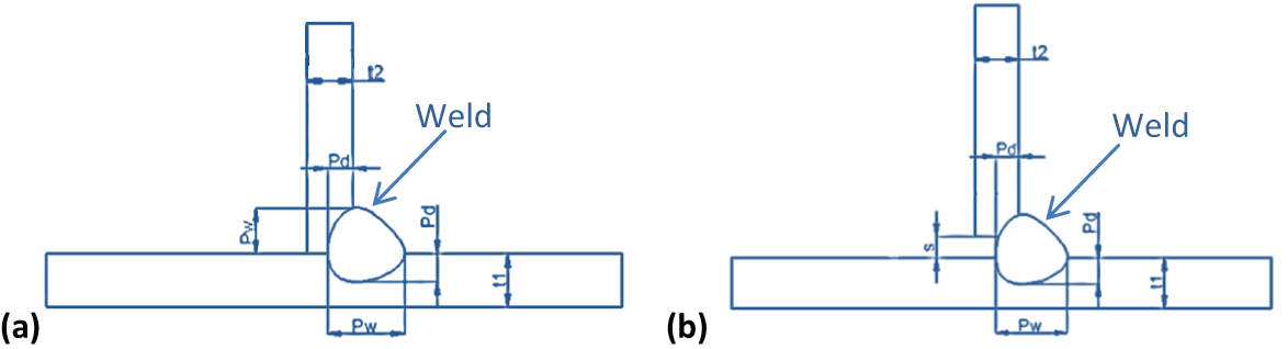
Flange couch weld dimensions: (a) flange weld with no gap and (b) flange weld with gap between the sheets. t1 and t2 are the sheets’ thicknesses, s is the gap size, Pw is the weld width and Pd is the penetration depth
The weld dimensions values are depicted in Figure 18. It is clear from Figure 18, which shows the weld dimensions for the flange couch weld, that there is no significant change in both penetration depth and weld width for the various welds. This can be related to two reasons; same welding parameters and the same weld configuration were used for all filler wires, and more importantly, no defects such as lack of fusion or root cracks were observed in these joints.
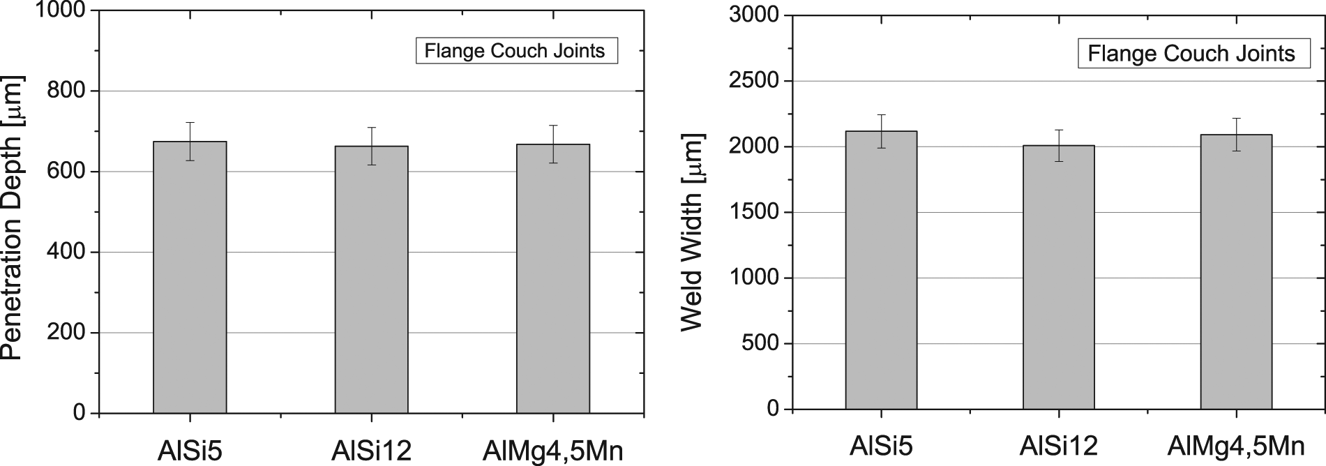
Weld dimensions for flange couch joints using various filler wires at 3.5 kW laser power and 35 mm/s welding speed.
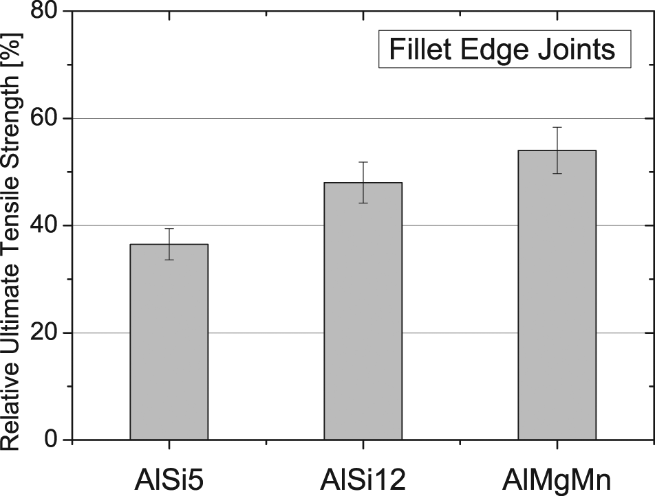
Tensile strengths of the joints were also evaluated to the ISO 6892-1 2009 standard and their values are given in Figure 19. It can be seen that AlSi12 (AA4047) welds showed the least tensile strength among other joints due to its containment of the highest porosity percentage. Porosity affects UTS directly since it reduces the cross-sectional area that carries the tensile load. The highest UTS value of more than 80% was achieved using AlMg4,5Mn (AA5083) filler wire which obtained its strength from the high magnesium content (more that 4.5%) and other alloying elements which form high-strength precipitates.
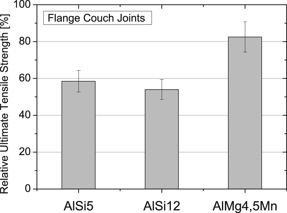
Tensile strength for various filler wires’ welds at 3.5 kW and 35 mm/s as a proportion of the base material UTS (195 MPa) for the flange couch joints.
Discussion
This work shows clearly that the addition of Mg and Mn to the filler wires can significantly reduce porosity and cracking compared to Al–Si filler wires in laser welding of the aluminium alloys. This is opposite to some of the previous findings7,8 when filler wires were not used. This may be attributed to the fact that Si element in the filler wires increases the fluidity of aluminium alloy by decreasing the viscosity to less than 1 cP at 700°C for alloys at 12% silicon. 7 This increases the disturbance in the weld pool especially at high welding speeds, which, in turn, enhances the entrapment of the gases inside the weld. Although the increase in Mg content increases hydrogen solubility in aluminium, the AA3004 filler wire contains more Fe and Cu than the base material and the other two filler wires, which, in turn, reduces hydrogen solubility to a certain level. 7 More importantly, the microstructure of the dendritic Al–Mg eutectics that are produced in the AlSi5 and AlSi12 welds makes magnesium evaporation much easier to occur than in the refined and rounded phases in the AlMgMn welds. In a previous study, it was found that the refinement of the microstructure in AA3004 welds reduces alloying elements’ evaporation and subsequently reduces porosity generation. 30
Keyhole stability is dependent on the vapour pressure inside the keyhole as well as the surface tension of the liquid. When the surface tension becomes greater than the vapour pressure, the keyhole collapses and results in voids inside the weld. 31 It is pertinent to mention that unlike Cu and Si, magnesium has lower boiling and melting points and has a very high vapour pressure that leads to a reduction in the surface tension of molten aluminium. 32 However, it may be possible that Mg helps to stabilise the keyhole and results in less porosity in welds with high Mg content.
It is worth mentioning that less porosity was observed in the flange couch joints in comparison with the filler edge ones although the same line energy (approximately 100 J/mm) was used. This can be attributed to the gap that exists at the root of the joint due to the joint’s configuration. This gap allows gases to escape from the weld while they are trapped inside the welding pool in fillet edge joints.
It should be noted that no cracks were observed in the welds produced in this work when Mg filler wires were used. Many researchers reported that some of the Al–Mg alloys can be used to produce welds that are free from solidification cracking.25,26,33 This can be attributed to the high Mg content (4.5%) which alters the FZ composition and reduces the weld crack susceptibility, as well as to its role in the formation of equiaxed grains in the FZ instead of the elongated grains which are associated with autogenous laser welding of 6000 alloys. The fine and equiaxed grains hinder cracks’ initiation and propagation in the FZ which is also observed when Al–Si filler wires are used.7,26
Some previous work reported that AA6013 alloy can be welded without filler wire using a fibre laser. However, the process window within which sound welds are produced was found to be very narrow (0.8–1.5 kW and 70–100 mm/s) and many defective welds were produced outside that range. 34 The work reported in this article shows that the use of filler wire broadens the process window within which low porosity welds can be achieved.
Conclusion
This work reported the effect of filler wires’ composition on the joint characteristics such as porosity, tensile strength and weld dimensions during laser welding. The work can be concluded as follows:
Porosity in fillet edge joints decreases from 80% (where AlSi5 filler wire is used) to less than 1.5% when AlMgMn filler wire is used. For flange couch joints, the maximum porosity proportion is observed in the AlSi12 joints (3%), while it is reduced to about 1% using AlMg4,5Mn filler wires. In both types of joints, filler wires with higher Mg and Mn content lead to a significant reduction in porosity.
Weld dimensions such as weld width and penetration depth for the fillet edge joints vary due to various weld defects such as lack of fusion and root cracks. However, no significant difference is observed in the weld dimensions in the flange couch joints due to the joint configuration.
The tensile strength (UTS) of the weld is maximum in the fillet and flange joints when AlMgMn and AlMg4,5Mn fillers are used, respectively. This can be attributed to the high Mg and Mn content in these wires compared to AlSi5 and AlSi12 fillers.
Further investigations may include an evaluation of the corrosion resistance as well as other mechanical properties such as impact and fatigue strength for the studied wires. The weld appearance is of a great interest for structural applications in which the outer skin should be sustainable, smooth and defect-free. Therefore, corrosion resistance can be explored in more detail. Moreover, a systematic design of experiment can be created to examine a wider process window using two or three filler wires.
Footnotes
Appendix 1
Declaration of conflicting interests
The author(s) declared no potential conflicts of interest with respect to the research, authorship, and/or publication of this article.
Funding
The author(s) received no financial support for the research, authorship, and/or publication of this article.