
Abstract
In this article, the lap joint of acrylonitrile butadiene styrene and polycarbonate is produced by submerged friction stir welding. The objective of this research work is to investigate the effect of welding parameters (rotational speed, traverse speed and plunge depth) on tensile strength. Maximization of weld strength (19.2 MPa) is achieved at a rotational speed of 1500 r/min, traverse speed of 40 mm/min and plunge depth of 1.0 mm. The macrostructure morphology and microstructure are analyzed using the optical microscope and scanning electron microscope. The major defects of the joints are cracks, pores and voids, which are the main reasons for decreasing the tensile strength.
Keywords
Introduction
The joining of plastic materials is essential part for producing large and complex structure. Generally, the joining methods for thermoplastics are mechanical bond, adhesion and welding. 1 Welding for thermoplastics is that the molten macromolecule mutually diffuses under the welding pressure and temperature until softened surfaces of materials are united. 2 Now, the novel plastic welding technology mainly involves several methods: laser welding,3,4 vibration welding, 5 friction stir welding (FSW), 6 ultrasonic welding 7 and so on.
FSW, as a novel solid-state joining technique, was initially invented at The Welding Institute (United Kingdom) in 1991 for mainly joining aluminum alloys such as highly alloyed 2XXX and 7XXX series which were considered difficult to be welded via the conventional fusion welding techniques.8,9 In the FSW process, a rotating tool with a special shoulder and pin slowly inserts into the workpiece until the shoulder contacts the workpiece surface. Under the weld heat generated by the friction and material plastic deformation, the material is softened and plasticized. With the rotation of the tool, the material moves from the front of the tool to the back and then forges into the joint. During the FSW process, the shoulder could not only prevent the plasticized material from overflowing but also break the oxide film on the workpiece. Compared with the fusion welding techniques, the FSW is regarded as an extremely attractive joining process due to its many advantages.
Although studies about FSW have been conducted, almost all of them were about FSW of metals. For thermoplastics, FSW has very attractive prospect because it is energy efficient, cost-effective and versatile. The researches on FSW of thermoplastics include polyethylene,10–14 polypropylene, 15 nylon, 16 poly(methyl methacrylate) (PMMA), 17 poly(ethylene-terephthalate-glycol) 18 and acrylonitrile butadiene styrene (ABS).19,20 The FSW of thermoplastics could not be considered as a solid-state process because the polymers do not have a single melting point (i.e. the molten materials were involved in weld regions). 21 Compared with the metallic material, thermoplastics have a low thermal conductivity, a very short solidification time and a low melting temperature. In the process of thermoplastics FSW, the low thermal conductivity would lead to nonuniform temperature distribution. The friction heat mainly concentrated in the weld nugget (WN). This resulted in the overheating of the material of WN and even degradation. Meanwhile, in this process, the material flow was difficult to control. As a result, the common FSW method does not achieve sound welding quality. In order to solve these problems and improve the properties of FSW joints, different methods had been used, including double-side FSW,10,11 in-process using a special tooling system6,12,19,20 and submerged FSW. The double-side technique has a high requirement for mounting workpieces. Using a special tooling system often made the experiments complicated and uncontrollable. The submerged FSW process took place under a specific ambient temperature. Present researches on submerged FSW mainly focused on aluminum alloy.22,23 The results confirmed that the mechanical properties of the underwater welded joint were significantly higher than those of the normal joint. During the process of submerged FSW, the water could not only decrease the peak temperature but also effectively control the thermal cycle. 24 In addition, the high-temperature distribution area was narrower than normal joint. 25 However, there are few reports about submerged friction stir weld on thermoplastics, especially for welding dissimilar thermoplastics.
In this study, submerged FSW was performed to weld ABS and polycarbonate (PC) plates. Figure 1 shows the schematic representation of submerged FSW. The effects of process parameters such as rotational speed, traverse speed and plunge depth on the weld strength, macrostructure and microstructure of the joints were investigated. The aim of this method was to reach practical applied solutions for welding dissimilar polymers.
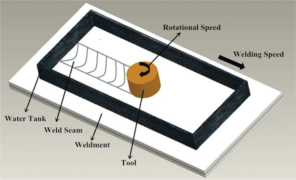
Schematic representation of submerged FSW.
Materials and experimental procedure
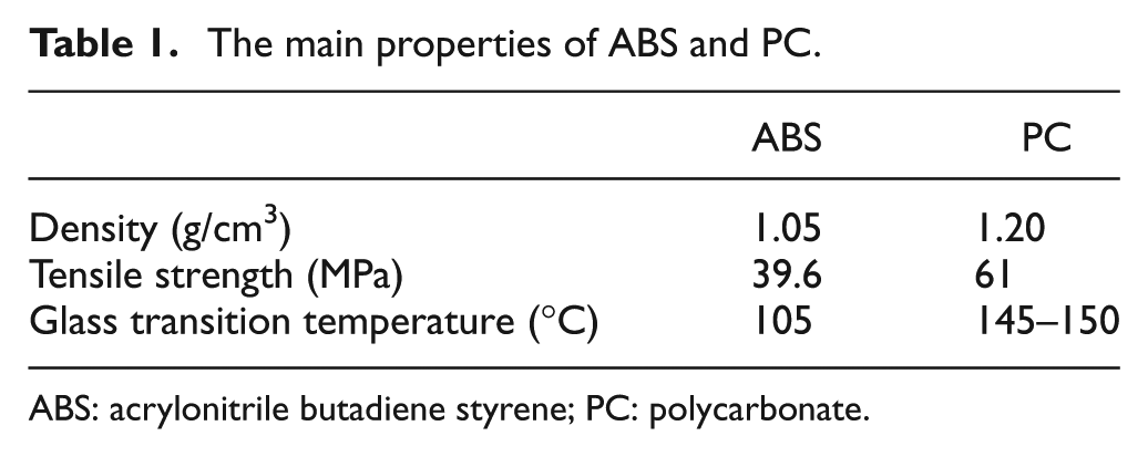
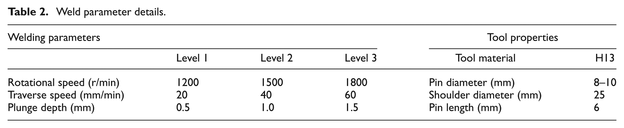
The samples used in this study consist of two 200 mm × 200 mm × 4 mm (length, width and depth) ABS and PC plates. The schematic illustration of welding setup is presented in Figure 2. The properties of materials are presented in Table 1. The joints are produced on modified milling machines. The rotating tool used in this experiment has a tapered pin. Figure 3 shows the schematic representation of the FSW tool. The tool and welding parameters are presented in Table 2. The rotating tool stays a short dwell time before moving forward along the joint line.
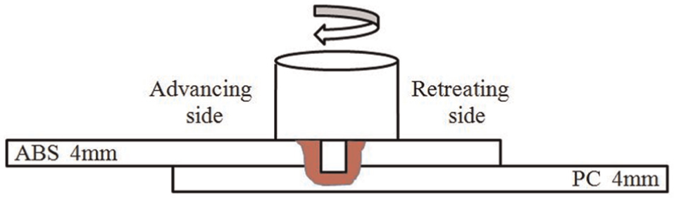
Schematic illustration of the friction stir dissimilar joint of ABS to PC in a single overlap configuration applied in this study.
The main properties of ABS and PC.
ABS: acrylonitrile butadiene styrene; PC: polycarbonate.
Friction stir welding tool.
Weld parameter details.
The weld tensile test was tested on the SANS CMT-5105 microcomputer control electronic universal tensile testing machine at room temperature, according to the GB/T 1040-92 standard. Figure 4 shows the tensile specimen used for studying the FSW under shear loading conditions. The strength was obtained by averaging strengths of five individual specimens, which were welded under the same parameters.
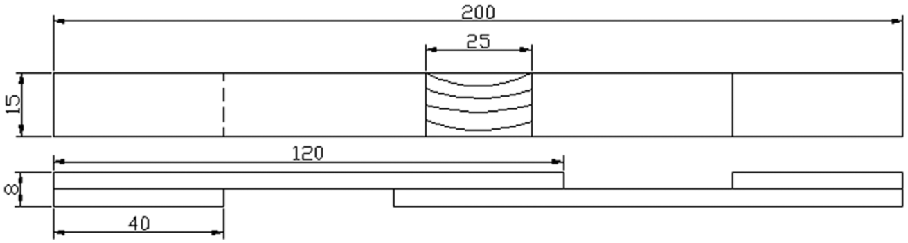
Configuration of tensile shear specimen (dimensions in mm).
For microstructure research, a new cross section was cut from the welded specimen using a LEICA RM 2235 model rotary-type microtome. The XJP-300 optical microscope (OM) was used to study an overview investigation of the cross section of the joints. The JSM-6360 LV scanning electron microscope (SEM) was applied to further analyze the welding interface of the specimens. For SEM analysis, the welded specimens were coated with gold.
Results and discussion
Macrostructure analyses
The macrograph in Figure 5 shows a typical joint segment, representative of the plane transverse to the weld travel direction of ABS–PC FSW joints. There were four distinct zones: base material (BM), heat-affected zone (HAZ), thermo-mechanically affected zone (TMAZ) and WN. The WN and TMAZ underwent plastic deformation and frictional heating. However, the deformation strain of TMAZ was not sufficient. The HAZ between the TMAZ and the WN was affected only by heat, and it often showed no apparent difference compared with the BM. Meanwhile, the width of the HAZ was very small due to the low thermal conductivity of the thermoplastics.
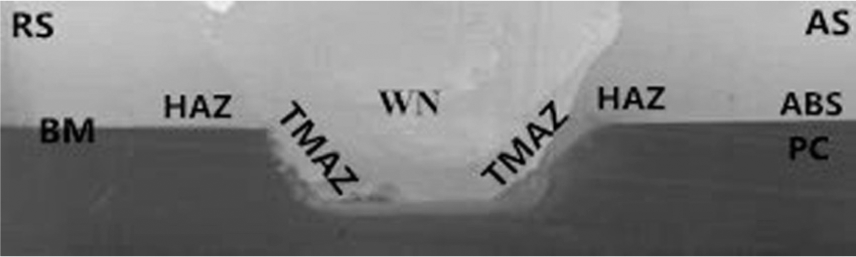
Macrograph showing overview of the transversal section of the weld seam of the ABS–PC submerged FSW joint.
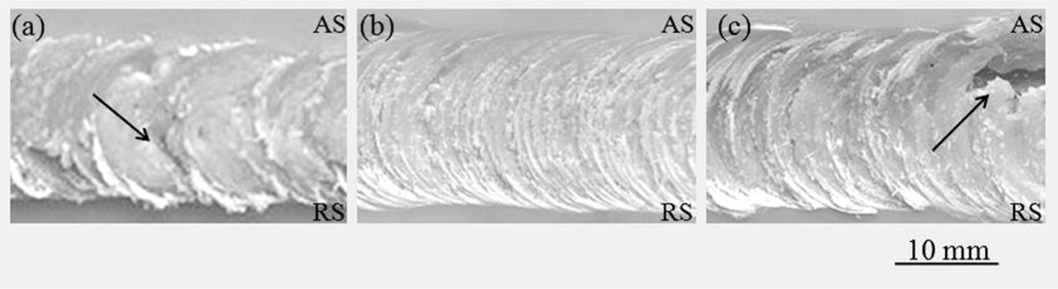
The weld surface quality could be used to evaluate the weld performance. Figure 6 shows the weld surface at different rotational speeds, and the traverse speed and plunge depth are 40 mm/min and 1.0 mm, respectively. In this study, all the weld surfaces appeared rough, and the weld surface showed striation shape, resulting from periodic deposition of materials. However, there was a clear dividing line (see the dotted lines in Figure 6(c)) in the middle of advancing side (AS) and retreating side (RS), and surface striations were broken in this region. This was due to thermal shrinkage after welding. Furthermore, the flash of materials is consistently present along the weld edge on the RS. The main reason for this phenomenon is the asymmetric flow of materials resulting from asymmetrical heat distribution, that is, the temperature of the AS was higher than the RS. 6 In the FSW process, the materials on the AS rotated with the pin, while it did not occur on the RS. The materials on the RS did not enter the rotational zone adjacent the pin; however, the materials on the AS formed the fluidized bed adjacent the pin and rotated around it. 20
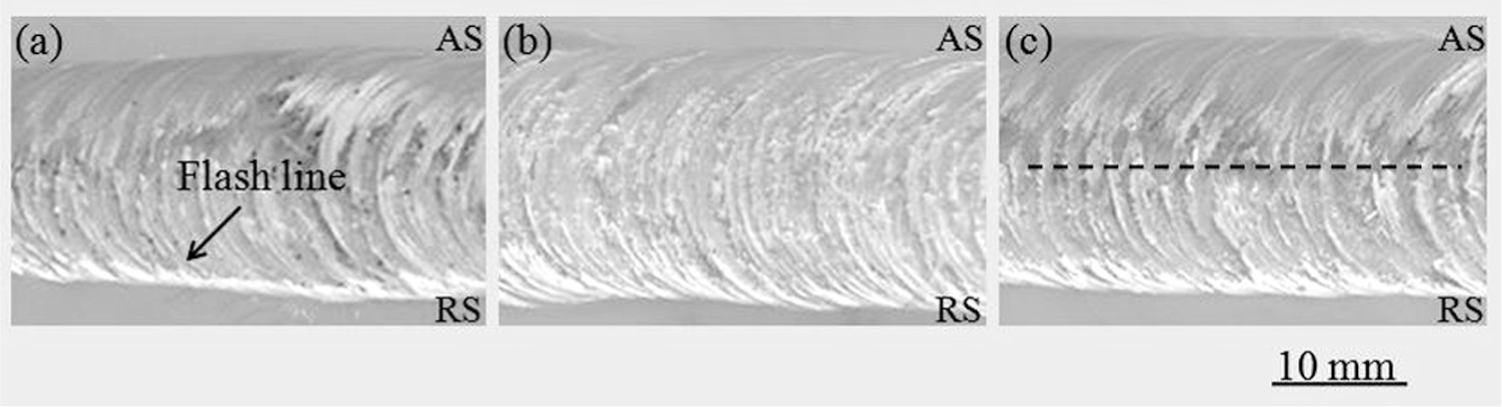
Macrograph of weld crown at different rotational speeds: (a) 1200, (b) 1500 and (c) 1800 r/min.
In the process of FSW, the total heat and parameters can be explained by 9
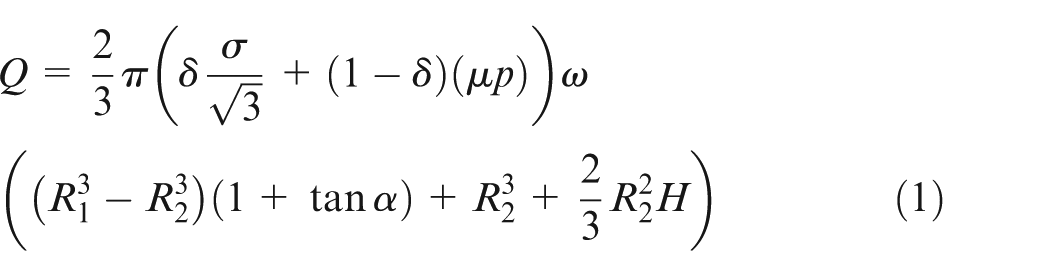
where Q is the total heat generation (W), σ is the yield strength (Pa), δ is the contact state variable, µ is the friction coefficient, p is the contact pressure (Pa), ωis the tool angular rotation rate (rad/s), R1 is the tool shoulder radius (m), R2 is the tool probe radius (m), α is the tool shoulder cone angle (°) and H is the tool probe height (m).
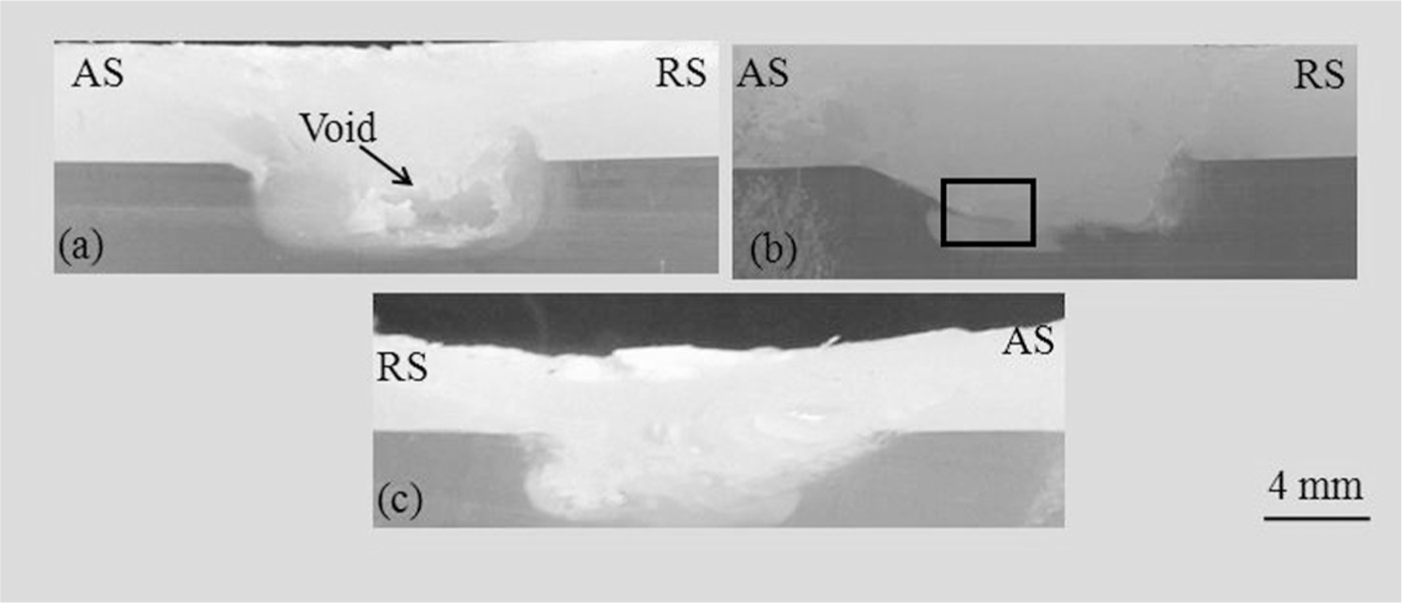
The effect of rotational speed on the macro-profile of transversal section of the weld seam is presented in Figure 7, and the traverse speed and plunge depth are 40 mm/min and 1.0 mm, respectively. According to equation (1), it could be deduced that the total heat generation was related to the rotational speed. When the rotational speed was low, the materials could not be fully mixed because of insufficient heating, which led to the existence of the no fusion area (crack). With increasing rotational speed, the heat increased to a decent value, and the materials of weld regions fully flowed and mixed. At the same time, the melted materials were stirred and squeezed, and macromolecular diffused in the whole weld surface, so that a good weld was formed. There were no obvious defects such as pores, cracks and voids. However, too high rotational speed (1800 r/min) would lead to too much heat concentrated on the nugget region, resulting in the formation of pores. These pores were controlled by trapped air, thermal shrinkage or environmental water. 6
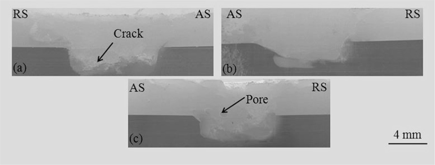
Transversal section of the weld seam of the ABS–PC submerged FSW joint at different rotational speeds: (a) 1200, (b) 1500 and (c) 1800 r/min.
Figures 8 and 9 show the effect of traverse speed on the macro-profile of weld surface and transversal section, and the rotational speed and plunge depth are 1500 r/min and 1.0 mm, respectively. The research of Kim et al. 26 indicated that the heat input was proportional to the inverse of welding speed. The weld surface made with the lower traverse speed (20 mm/min) was bumpy (see arrow in Figure 8(a)), and it had an irregular pattern, which was mainly due to the excessive melting of the increment of the local material in weld regions. When excessive heat concentrated in a narrow weld region for a long time, the surface was vulnerable to pores in weld region. Nevertheless, it easily led to the existence of no fusion area (crack) in interface and rough weld surface at too high traverse speed (60 mm/min) (see arrow in Figure 8(c)) due to the inadequate flow and mix of materials caused by the insufficient local heat. Meanwhile, the striation shape was discontinuous at higher traverse speed.
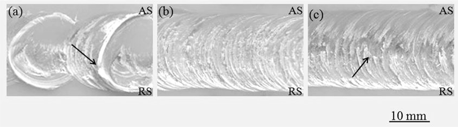
Macrograph of weld crown at different traverse speeds: (a) 20, (b) 40 and (c) 60 mm/min.
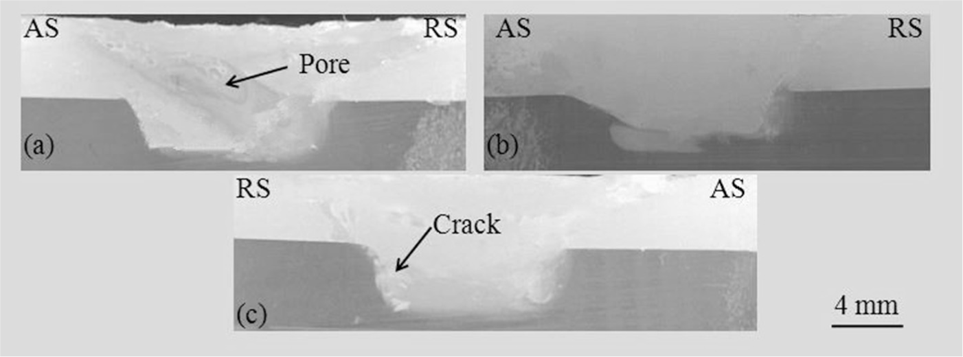
Transversal section of the weld seam of the ABS–PC submerged FSW joint at different traverse speeds: (a) 20, (b) 40 and (c) 60 mm/min.
The effect of plunge depth on the macro-profile of weld surface and transversal section is presented in Figures 10 and 11. The rotational speed and traverse speed are 1500 r/min and 40 mm/min, respectively. The weld surface that performed with the smaller plunge depth (0.5 mm) displayed irregularly, and the molten materials were deposited on the weld regions, causing the formation of voids in weld region. When the plunge depth was too large, the molten materials were extruded by the shoulder. As a result, the thickness of the upper sheet decreased.
Macrograph of weld crown at different plunge depths: (a) 0.5, (b) 1.0 and (c) 1.5 mm.
Transversal section of the weld seam of the ABS–PC submerged FSW joint at different plunge depths: (a) 0.5, (b) 1.0 and (c) 1.5 mm.
In the FSW for metals, the main concentrative position of defects was in the AS. 24 However, one phenomenon that had been noticed is that the defects, such as cracks, pores and voids, tended to occur on the RS. In FSW thermoplasts, the partially melted polymeric materials on the RS were extruded against the BMs on the AS, which led to the lack of materials on the RS. This accelerated the formation of defects. 17
A magnified view of Figure 11(b) is shown in Figure 12. A macro-interlocked structure, which might be conducive to improve the joint strength, was formed between both polymers. The long PC flash was inserted into the ABS base, which could tightly lock both polymers. As shown in Figure 12, the ABS and PC around the PC flash were closely contracted, with no micro-crack resulting from weld residual stress.
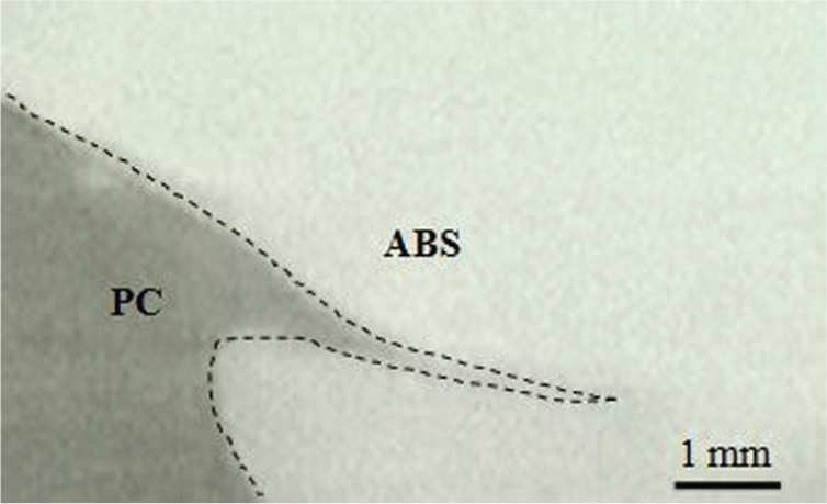
Nail effect formed by long PC flash inserted into the ABS.
Interfacial microstructures of the joints
Figure 13 shows micro-morphologies of a group of welds made by submerged FSW at different rotational speeds, with a traverse speed and plunge depth of 40 mm/min and 1.0 mm, respectively. At lower rotational speed (1200 r/min), the materials could not be softened sufficiently by friction heating, and the cracks (i.e. no fusion areas) were found at the interface, as shown in Figure 13(a). With the increase in the rotational speeds, the cracks disappeared (Figure 13(b)). However, there were many pores at a greater rotational speed, which might result from trapped air, thermal shrinkage or environmental water. 17 The increased friction heating might be responsible for such micro-morphology evolution of the joining interface. 27
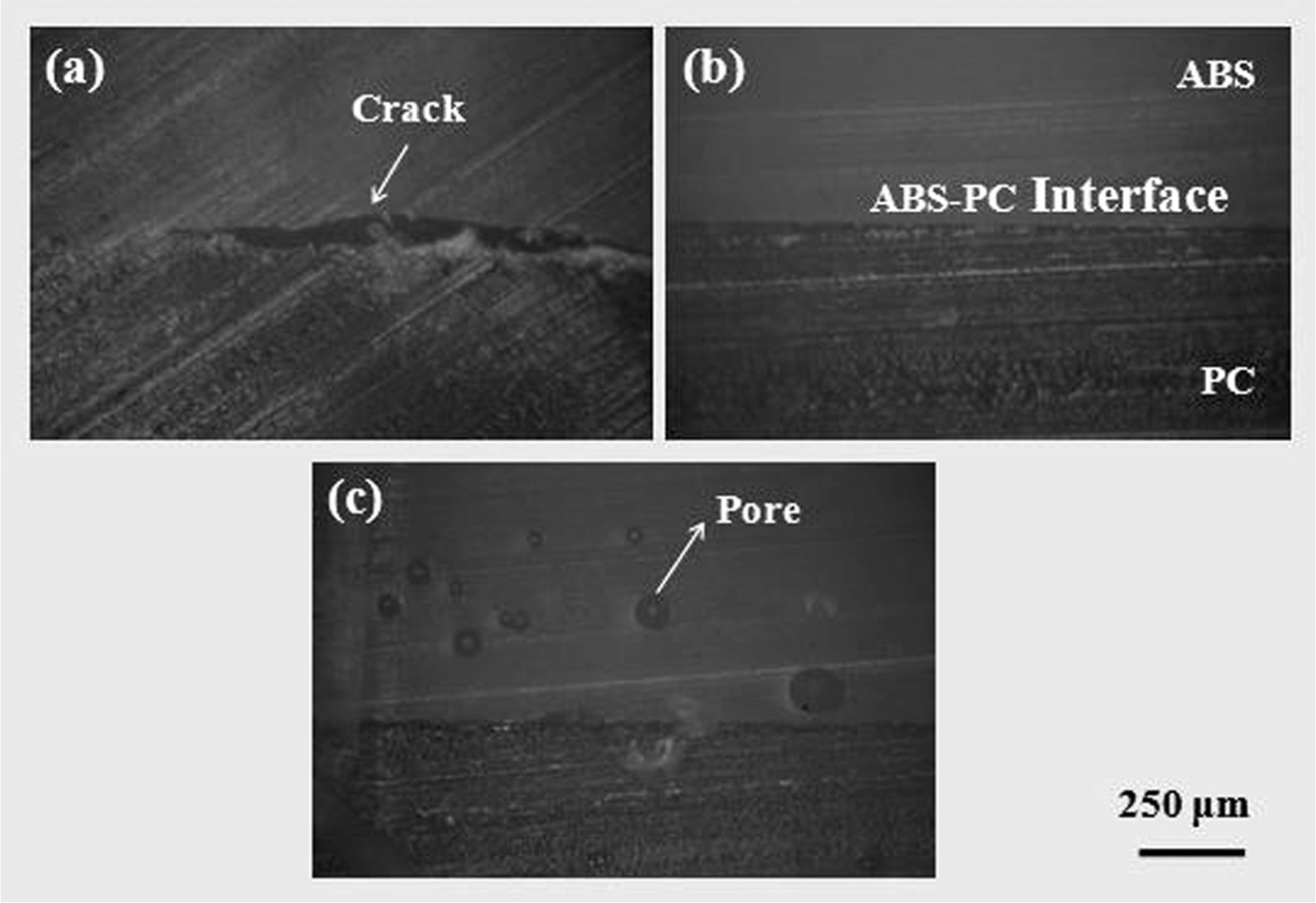
The micro-morphology of the joint at different rotational speeds: (a) 1200, (b) 1500 and (c) 1800 r/min.
Figure 14 shows the SEM microstructures of the ABS–PC joint from Figure 13(b). As can be seen from Figure 14, a continuous and uniform interface was distinctly visible between the ABS and PC bulk. There were no micro-cracks or voids which commonly existed in the welding of heterogeneous materials. Thus, the maximum tensile strength was achieved under these welding conditions.
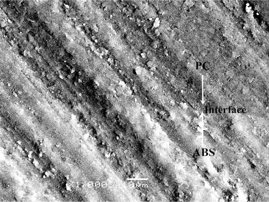
The SEM backscattered electron image (BEI) of the interface region.
The tensile tests of the joints
As the metric of mechanical properties test, the tensile property was used to evaluate the influence of the process parameters (rotational rate, traverse speed and plunge depth) on the weld quality.
Figure 15 shows the effect of rotational speed on the tensile strength of the sample by FSW. The traverse speed and plunge depth are 40 mm/min and 1.0 mm, respectively. It was revealed that the tensile strength of the sample increased with the rotational speed from 1200 to 1500 r/min. However, by further increasing the rotational speed from 1500 to 1800 r/min, the tensile strength decreased. As can be seen from equation (1), the total heat generation increased with increasing rotational speed. The lower rotational speed gave rise to insufficient flow and mix of the materials in weld regions. 20 There exists a region where the materials were not fully fused between the weld and BMs (crack). However, this easily led to the excessive fusion of materials in weld regions and made the weld process uncontrollable when the rotational speed was further increased. In this case, it easily formed a pore. These defects, such as crack and pore, acted as stress concentration points, which were likely to result in the decline of the tensile strength. 6
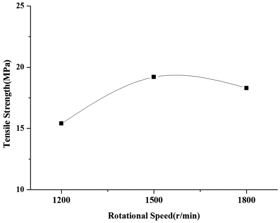
Effect of rotational speed on the tensile strength.
Figure 16 shows the effect of the traverse speed on the strength of the joints. The rotational speed and plunge depth are 1500 r/min and 1.0 mm, respectively. It indicated that the tensile strength increased first and then decreased with increasing traverse speed. The traverse speed affected the heat input per unit length of weld and thus controlled the degree of fusion and mixing ability of the weld material. 28 Although lower welding speed could promote the material flow, a large amount of friction heating concentrated in the nugget zone due to the low thermal conduction of polymeric materials, and the pore appeared along with the material melting. At higher welding speed, there was not enough time to melt the polymer materials. 13 This would lead to weak mixing of weld materials, thereby decreasing the tensile strength.
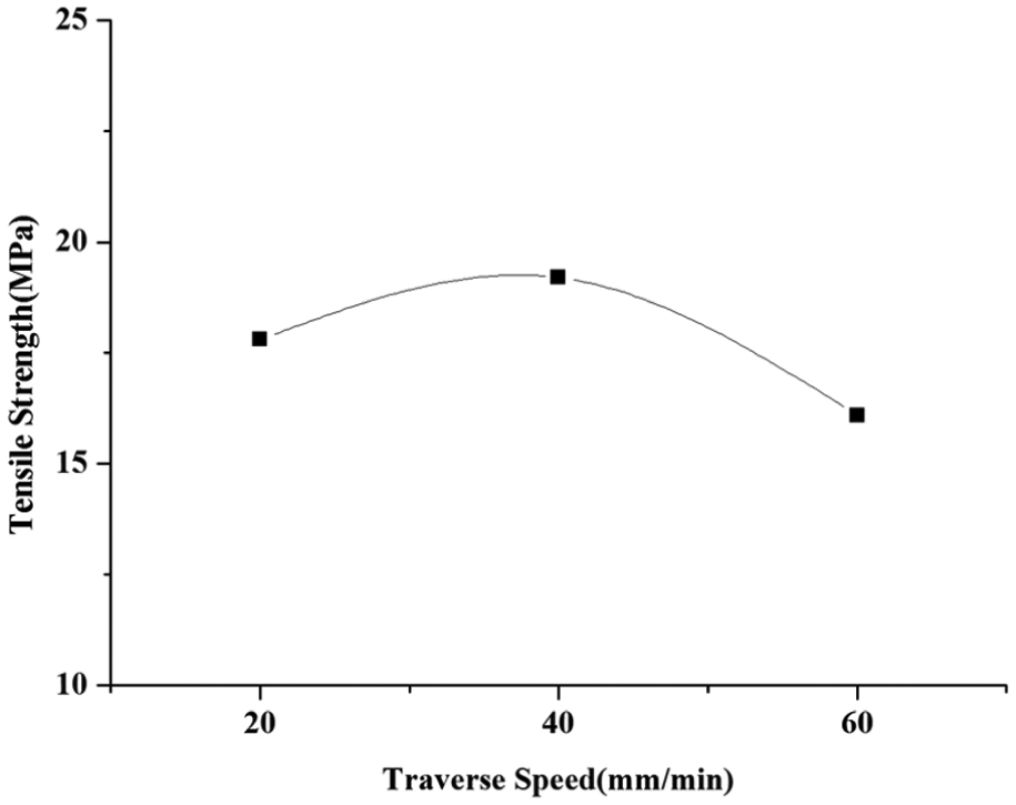
Effect of traverse speed on the tensile strength.
Figure 17 shows the effect of plunge depth on the strength of the joints. The rotational speed and traverse speed are 1500 r/min and 40 mm/min. The material mixing and heat transferring were insufficient at a small plunge depth due to the shoulder and workpiece having the least contact, 28 which could lead to strength reduction. When the plunge depth was deeper, the upper plate would be thinner, leading to decreasing strength.
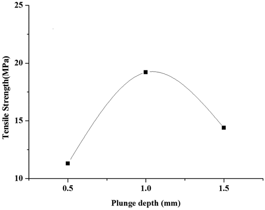
Effect of plunge depth on the tensile strength.
Conclusion
In this article, ABS and PC were successfully friction stir welded under water employing different weld parameters in order to investigate their effect on the macrostructure morphology, interface microstructure and tensile strength of joints. The following conclusions could be drawn:
Sound joints could be obtained using conventional tool by submerged FSW, and the macrostructure morphology, interface microstructure and tensile strength of joints varied depending on weld parameters.
Good tensile strength (19.2 MPa) was achieved with the rotational speed of 1500 r/min, traverse speed of 40 mm/min and plunge depth of 1.0 mm.
The major defects of the joints were cracks, voids and pores, which were the main reasons for the decrease in tensile strength.
In FSW of polymer, the main concentration of defect was in the RS, which was the location of fracture of the joints in the tensile test.
Footnotes
Declaration of conflicting interests
The authors declare that there is no conflict of interest.
Funding
This work was supported by the National Natural Science Foundation of China (grant number 51475232). This is a project funded by the Priority Academic Program Development of Jiangsu Higher Education Institutions.