
Abstract
This work is to assess whether car bumpers can be formed using single-stroke pressing instead of conventional double-stroke pressing. Some basic characteristics of the car bumper forming process are also clarified. An incremental elasto-plastic finite-element method is used to simulate a bumper forming process using high-strength steel and laminate sheets under the plane strain condition. Simulations clearly demonstrate the processes involved in single-stroke forming. A three-layer steel/polymer/steel laminate developed for vibration-damping in an automobile bumper is also tested to demonstrate how shear defects occur between the two skin steel layers along the entire length of the laminate sheet in simulation. The springback phenomenon resulting from the elastic recovery is observed in simulations of the final bumper shape. Accordingly, experiments for high-strength steel sheet were performed to verify the numerical simulation and to investigate how process geometry conditions affect the springback angle, which is an essential consideration when assessing and controlling the final bumper shape in practice. This work improves understanding of the bumper forming processes used in the automotive industry.
Introduction
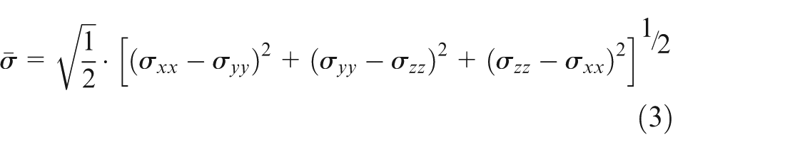
A bumper is a protective component made of metal, rubber or plastic and mounted on the front and rear of a vehicle. When a low-speed collision occurs, plastic deformation in the bumper system absorbs the shock (impact energy) and prevents or reduces damage to the front and rear ends of the vehicle. The conventional steel bumper has many advantages such as good load carrying capacity. However, its limitation is a low strength-to-weight ratio. The trend toward use of lightweight automotive structures has in the widespread use of high-strength steel (HSS), advanced high-strength steel (AHSS) or composites as replacement materials for conventional steel. Bumpers made from these lightweight materials absorb more collision energy compared to steel bumpers. Another major advantage over steel bumpers is their reduced weight. Osuga 1 emphasized that vehicle weight reduction primarily resulted in energy savings and oil economy, which made lightweight vehicles with improved vehicle crashworthiness through optimization. Xichan 2 analyzed the automotive frontal crash test regulation and its tendency regarding crashworthiness, lightweight design and energy economy. The present work compared steel bumpers conventionally used in passenger vehicles with bumpers composed of HSS or laminate sheets. Industrial demand for the new bumpers is high because of their vibration-damping characteristics and their lightweight, which reduces energy consumption.
During metal forming, plastic deformation can substantially affect the final shape, depending on the material used. These material properties are important inputs to computer-aided engineering analyses of component response such as models for analyzing a car bumper during a crash or for analyzing the durability of a car bumper. A change in these properties could substantially affect the results of such analyses and could lead to a sub-optimal design. Bumpers are one of the simplest and most common impact energy-absorbing devices currently used in automobiles. The impact energy-absorbing devices are capable of bringing a moving mass to a controlled stop depending on how much energy is absorbed by plastic deformation. Recently, HSS sheet has been used to satisfy the industrial demand for lightweight auto parts that can increase energy efficiency. Ohwue et al. 3 reported the experimental results and finite-element (FE) analyses of springback in bending forming of bumper model for HSS sheets. Hariharan et al. 4 examined the techno-economic merits of automotive engineering materials. A bumper made from lightweight stainless steel stamping satisfied the vibration test requirement. Accordingly, a new composite sheet composed of a three-layer steel/polymer/steel laminate has also been developed for vibration-damping of automobile parts and panels, such as vehicle bumper for shock absorbers. Kleisner and Zemčík 5 applied Research Council for Automobile Repairs (RCAR) methodology in a numerical simulation of a composite material used to reinforce car bumpers. Recently, Prabhakaran et al. 6 investigated the design and fabrication of a composite bumper for light passenger vehicles. Compared to a steel bumper, the composite bumper had a 64% higher safety factor and an 80% lower cost. By using a composite material, the weight of the bumper was reduced by 53.8% without sacrificing the strength. Additionally, several works have studied how bending forming of composite sheet affects vibration-damping in a vehicle bumper. Yoshida 7 reported how the press formability of vibration-damping sheets is affected by extremely small deformation resistance of the core film. Hirose et al. 8 concluded that decreased shear deformation of the core films reduces press failures during deformation of laminated sheet. Itoh et al. 9 investigated the elasto-plastic bending relevant to the press formability of sandwich plates. Huang and Leu 10 reported FE simulation results for a bending process in laminate sheets. Figure 1 shows the structures of a three-layer steel/polymer/steel laminate sheet. Although composite steel has excellent vibration-damping properties, the steel/polymer/steel laminate has poor formability. Geometrical defects often occur in the forming process, typically in the bending operation. One example is an occasional shear between two skin steel layers along the entire length of the sheet, even when the deformation is non-severe. This problem does not occur during bending of a simple steel sheet.
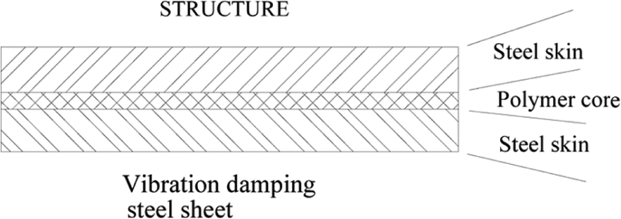
A three-layer steel/polymer/steel laminate sheet.
Besides, Liu and Day 11 reported the results of experimental analyses and computer simulations of an automotive bumper system under impact conditions. Avery and Weekes 12 developed a new low-speed impact test for improved measurement of bumper performance and compatibility. Qi et al. 13 applied a nonlinear FE method (FEM) to perform a frontal crash simulation of a commercial vehicle to improve the crashworthiness of energy-absorbing structures. Yildiz and Solanki 14 reported a new particle swarm-based optimization method for multi-objective optimization of vehicle crashworthiness to improve passenger safety and to reduce costs in the early stage of vehicle design. Kim and Won 15 studied structural variables that affect automotive body bumper impact beam. Rao and Murthy 16 designed an injection mold for a front bumper and analyzed its impact characteristics. On the other hand, Haag et al. 17 investigated the characteristics of aluminum foams, which are developed to apply in lightweight construction upon stiffness and impact absorption (crushing resistance), using uniaxial compression tests. Gantner et al. 18 theoretically investigated the technique of free-bending process, which is highly applied in the manufacture of car components due to fast bending speed and free definable bending geometry and verified by experiments. Huang et al. 19 estimated springback of indirect hot press forming for manufacturing automobile structural components of ultrahigh-strength steels, reducing weight and improving crashworthiness, under varied cooling rate.
An incremental elasto-plastic FEM for bumper forming is used to investigate (1) the feasibility of replacing the double-stroke pressing method conventionally used for bumper forming with the single-stroke pressing method shown in Figure 2, (2) the causes of increased complexity of asymmetric springback compared to a single bending point and (3) the formability and deformation characteristics of bumper formed from a three-layer laminate of HSS-polymer-HSS (vibration-damping steel for safety purpose). Accordingly, experiments were performed to verify the numerical simulation and to investigate (4) how process variables, including punch and die corner radius and clearance, affect springback after bumper forming. The simulations also clearly demonstrate the processes that typically generate a shear defect between the two steel surface layers along the entire length of the laminate sheet. The calculated sheet geometries and the velocity distributions are also simulated to observe the characteristics of the overall bumper forming process and to improve understanding of the bumper forming process in industry needs.
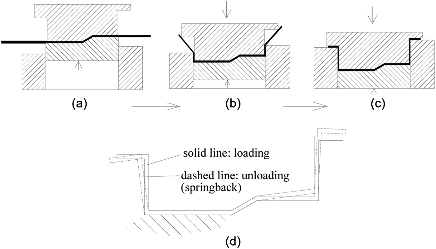
Initial steps in conventional bumper forming processes: (a) cushion forming (first step), (b) bumper forming (second step), (c) final stroke (under loading) and (d) bumper shapes.
Analysis
The bumper forming process is simulated by an incremental elasto-plastic FEM based on the updated Lagrangian formulation under the plane strain condition. A weighting factor
FE formulation
By using the Jaumann rate of Cauchy stress introduced by McMeeking and Rice, 20 the rate equation for virtual work can be expressed in updated Lagrangian form as
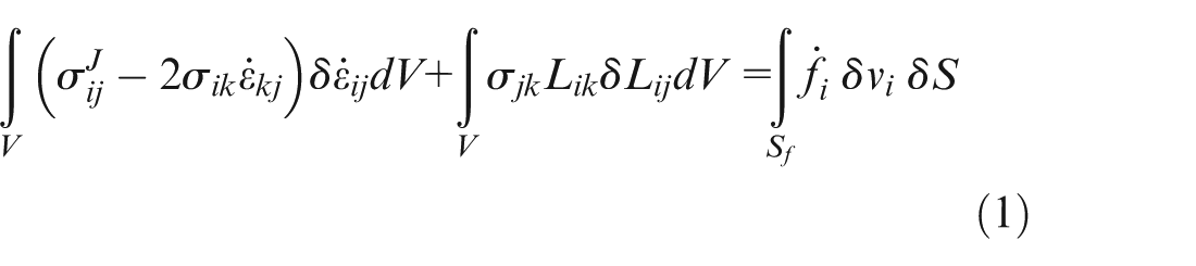
where
The constitutive relation, which incorporates small elasto-plastic finite deformation behavior, is expressed as
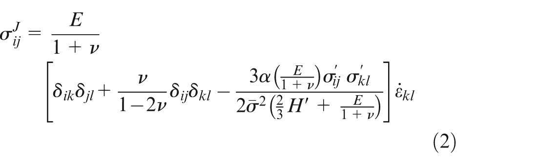
where
where

where n denotes the strain hardening exponent and K represents a material constant.
By performing a standard FE discretization procedure, equation (1) yields a system of algebraic equations, which can be expressed in matrix form as
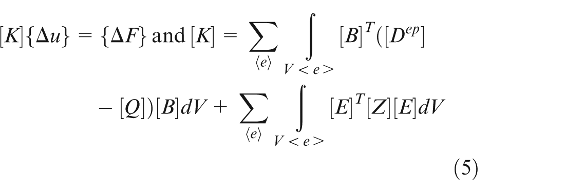
In the above equations, [K] is the global elasto-plastic tangent stiffness matrix, which is a constant within each incremental step;
In this work, the friction effect was ignored in contact layer because the later pretest of lubrication effect (with and without lubrication) shows that the geometrical effect is larger than the friction effect in this work. The friction effect seems to be suppressed or submerged by the geometrical effect. To ensure the accuracy of this explicit integration scheme (static explicit formulation), the weighting factor
Unloading process
Performing unloading or elastic recovery is a very important process to obtain the final shape of bumper in simulation. There are various methods for unloading simulation, such as Lee et al. 22 incorporated the modified Chaboche model, isotropic–kinematic hardening laws and non-quadratic anisotropic yield functions to examine the effect of hardening law on springback and to improve the springback evaluation of automotive sheets. Guo et al. 23 proposed two simple and efficient discrete Kirchhoff triangular (DKT) shell elements for the springback simulation in sheet forming process. Hama et al. 24 used Nagata patch for describing tool surfaces to improve tool modeling accuracy and to clarify its effect on springback prediction. In this work, the following unloading process has been widely used, and its correctness has been verified by many researchers, for example, Huang et al., 25 Huang and Leu 26 and Leu. 27
In this work, the final shape or the springback behavior is determined by executing the unloading process under the assumption that the properties of all elements are reset to elastic. The force of the contact node is reversed, which makes it the prescribed force boundary condition. All tools are removed for the elastic unloading procedure. The present unloading process is simple and effective.
Results and discussion
A car bumper is one of the simplest and most common impact energy-absorbing safety devices used in the automobile industry. By absorbing energy, plastic deformation of a bumper can bring a moving mass to a controlled stop. Figure 3 shows the shape of a bumper before and after unloading at the final stage of forming. One feature of the bumper is the occurrence of springback. In practice, the final shape or the springback behavior resulted from the elastic recovery of bent sheet as all tools are removed when the bending process finished a bumper forming. Then, the deformation of elastic recovery (unloading) is induced and the springback occurred. In this work, the bumper forming process is first simulated by an incremental elasto-plastic FEM to clarify some basic characteristics of the bumper forming process. The single-stroke pressing model is used instead of the conventional double-stroke pressing model (Figure 2). The formability and deformation characteristics of a bumper formed fromHSS-polymer-HSS three-layer laminate sheet (vibration-damping steel for safety purpose) are simulated for a clear demonstration of the processes that typically generate a shear defect between the two skin steel layers along the entire length of the laminate sheet. In FE simulation, three-layer elements are divided for steel/polymer/steel laminate sheet and two-layer elements for HSS sheet in thickness direction. The existence of complete adhesion with no peeling and no sliding at the interface between two layers of the sheet is assumed in simulation. Accordingly, a series of experiments were performed to verify the numerical simulation results and to investigate how process variables such as punch and die corner radius and clearance affect bumper deformation.
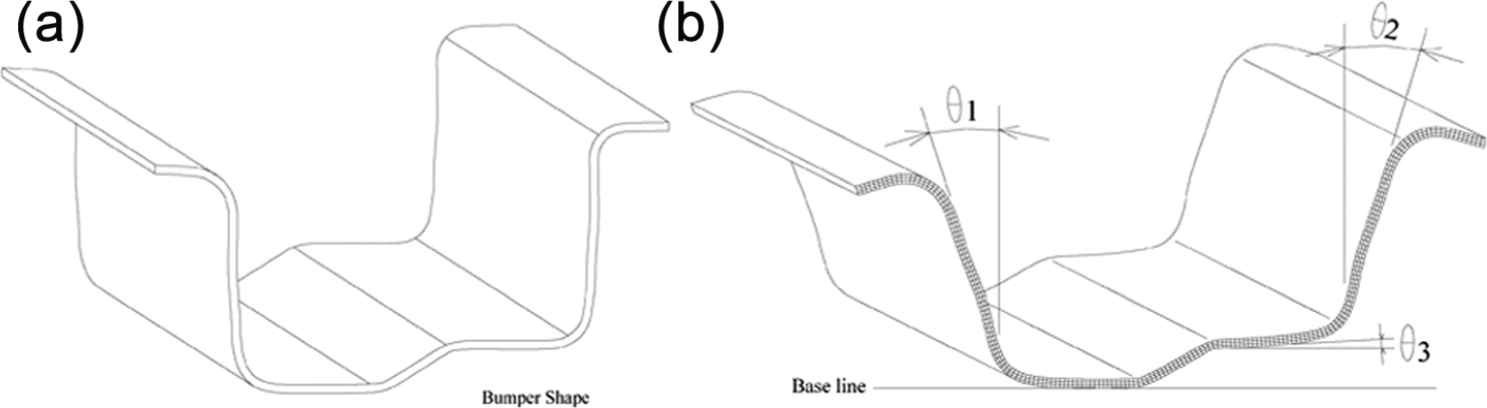
Bumper shape before and after unloading at the final forming stage: (a) bumper shape under loading and (b) bumper shape after loading.
Figure 4 shows the investigated bumper forming model, where Figure 4(a) shows the fixed-type bumper forming process and Figure 4(b) shows the free-type bumper forming process. The FE simulation is used to determine which is the better forming type, the fixed type or the free type. This better forming type is used for the bumper forming model in this work. Table 1 shows the material properties of HSS for experiment and laminate sheets for FE simulation. The SPFC 440 steels (JIS G3135) were made by China Steel Corporation (CSC). The material properties of laminate sheets, acrylic acid copolymer (CHT) and polyester (CNT), were obtained from the work of Huang and Leu. 10
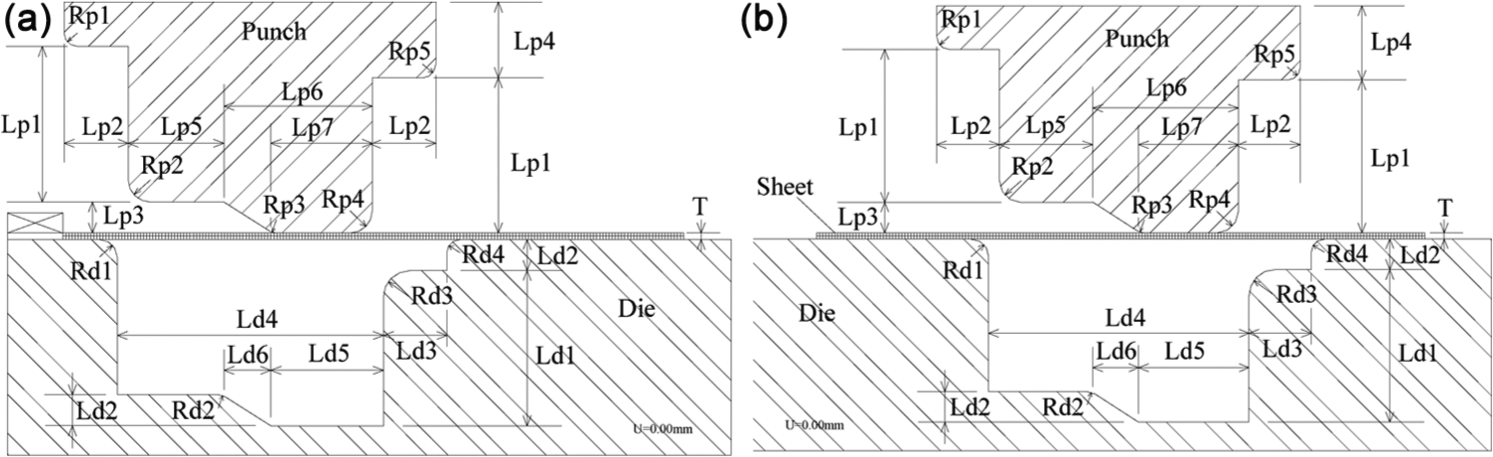
(a) Fixed-type bumper forming process and (b) free-type bumper forming process.
Material properties of HSS sheet and laminate sheet for vibration-damping.
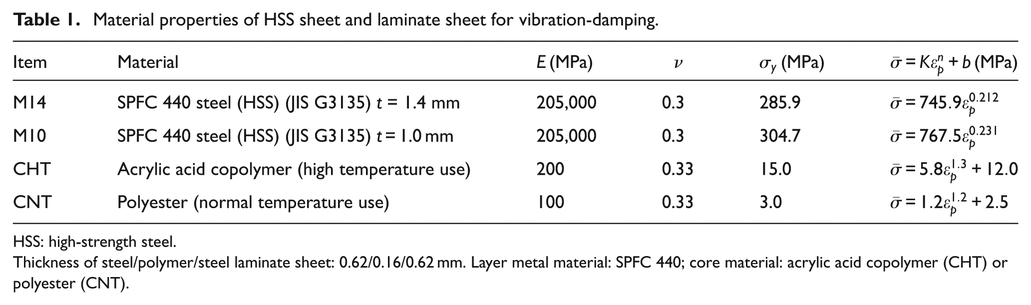
HSS: high-strength steel.
Thickness of steel/polymer/steel laminate sheet: 0.62/0.16/0.62mm. Layer metal material: SPFC 440; core material: acrylic acid copolymer (CHT) or polyester (CNT).
Occurrence of necking in fixed-type bumper forming
Figure 5 shows how necking in fixed-type bumper forming results from geometrical constraints on bending at points A, B and C, where Figure 5(a) shows the case of HSS sheet and Figure 5(b) shows laminate sheet. Moreover, comparing the simulation results of three element sizes in parts (i)–(iii) of Figure 5(a), it clearly shows that the effect of FE mesh (element size) on the necking phenomena is little. Apparently, fixed-type bumper forming is unsuitable for forming a bumper by a single-stroke operation. Therefore, this work developed and characterized a free-type bumper forming process.
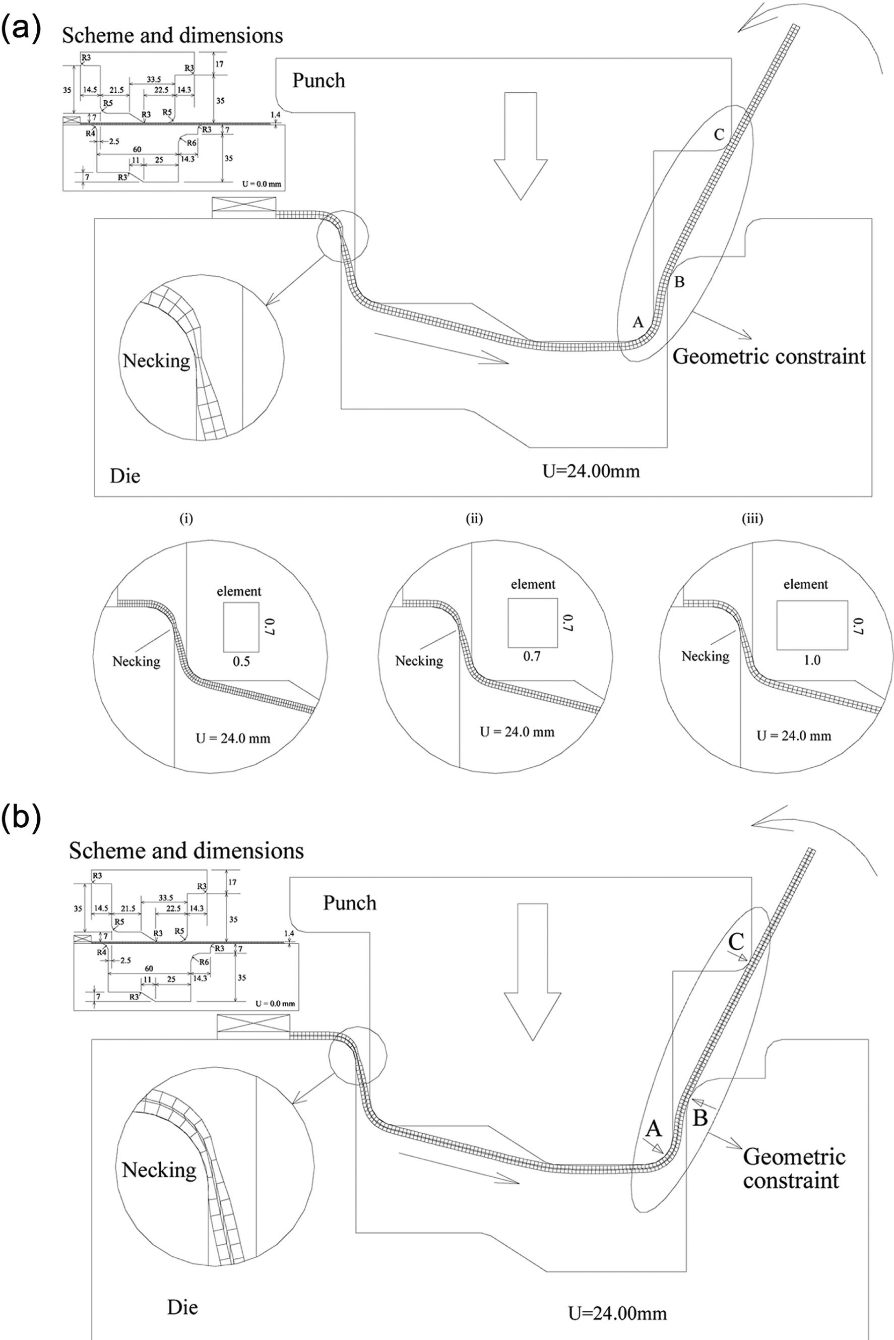
Comparison of necking in (a) SPFC 440 steel and (b) high-temperature vibration-damping steel sheet with acrylic acid copolymer core (clearance Cr=2.5mm, thickness t=1.4mm).
Simulation of bumper forming with steel/polymer/steel three-layer laminate with vibration-damping
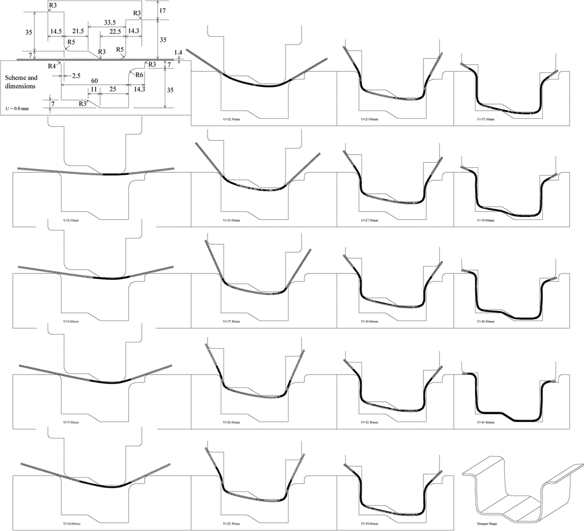
Figure 6 shows the bumper mold scheme and dimensions used for FE simulation. Figure 7 shows the distribution of punch load with punch stroke for CHT laminate sheet (SPFC 440/acrylic acid copolymer/SPFC 440). In the early stage, the punch load increases gradually. In the final stage, however, it increases rapidly with punch stroke due to the large bending effect. Figure 8 shows the overall bumper forming process, including the deformation and velocity distributions of the high-temperature vibration-damping laminate steel sheet at 18 different forming stages. The arrows show the direction of material flow during bending. By gradual bending, the sheet was easily fitted to the die cavity before forming the final bumper shape. However, Figure 9 shows two defects observed in bumpers formed from steel/polymer/steel laminate sheet: shear deformation and edge defect during the final forming. The bending characteristics of bumper forming, both shear deformation and edge defect, are clearly visible. In general, high shear deformation weakened the core film and increased the failure rate. Figure 10 also shows that shear deformation between the two skin steel layers occurs along the entire length of the sheet in the cases of CNT (Figure 10(a)) and CHT (Figure 10(b)). The shear defect in the core resulted from the relatively weak polymer compared to the metallic faces. The magnitude of shear depends on the position of the material. In Figure 10, two large shear regions, I and II, in the die radius area result from a severe bending effect, which induced geometrical constraints to obstruct metal flow on the contact surface, in the area near the die arc. Figure 11 compares springback after unloading in the final forming stage in the cases of CNT (Figure 11(a)) and CHT (Figure 11(b)), which are the actual shapes of the bumper.
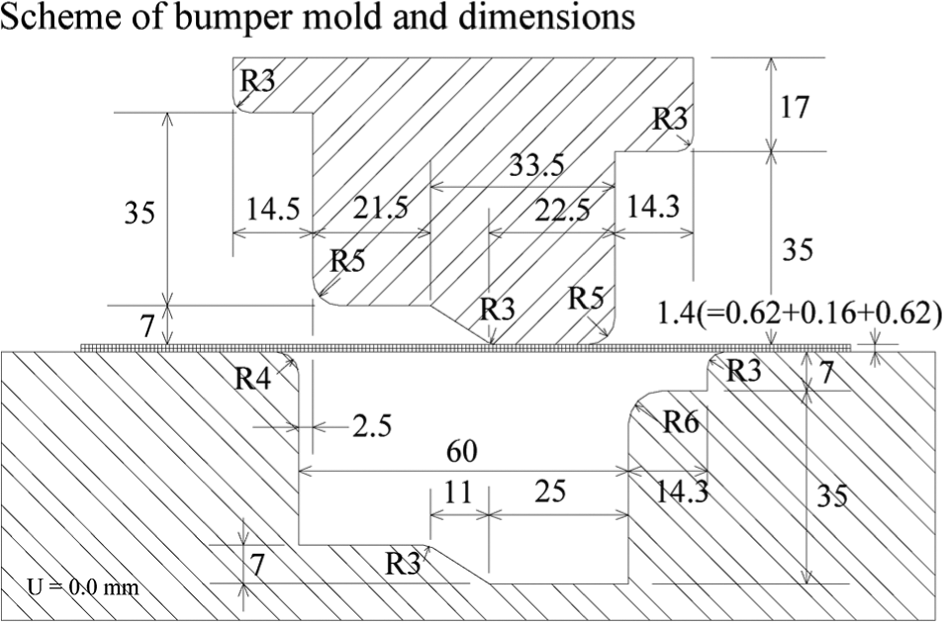
Schematic diagram of bumper mold (in mm).
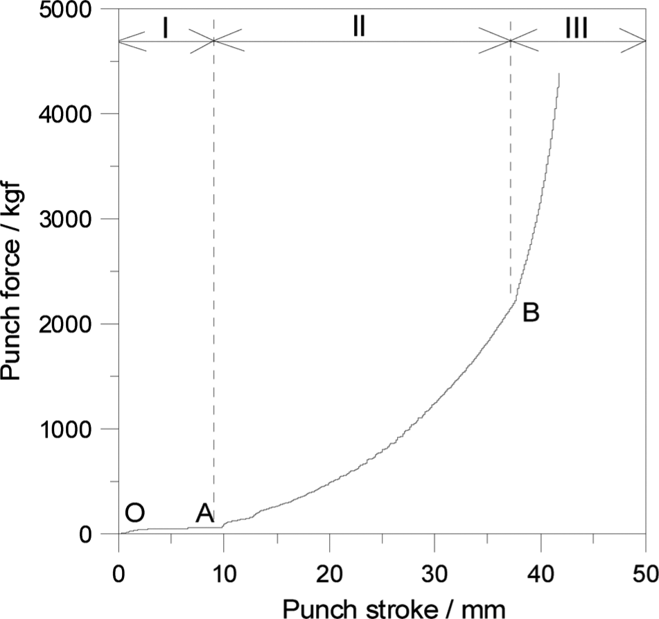
Distribution of punch load with punch stroke.
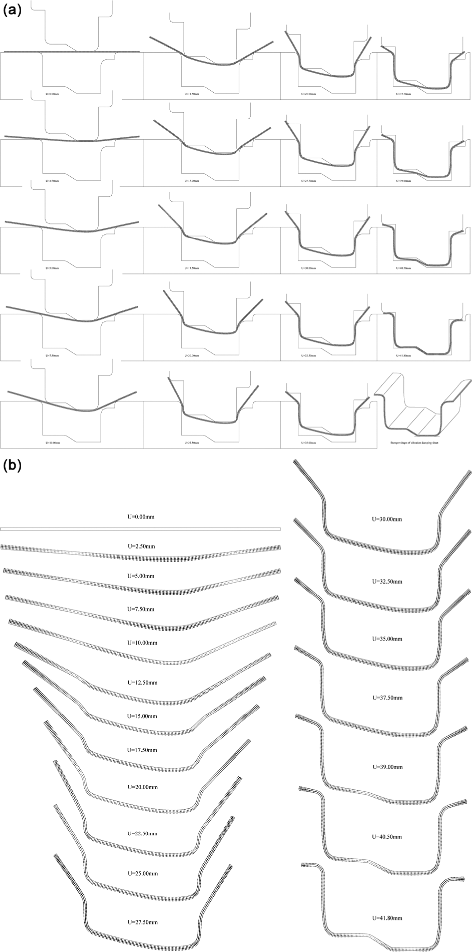
Overall bumper forming process using laminate sheet with damping-vibration: (a) deformed shapes and (b) velocity distributions.
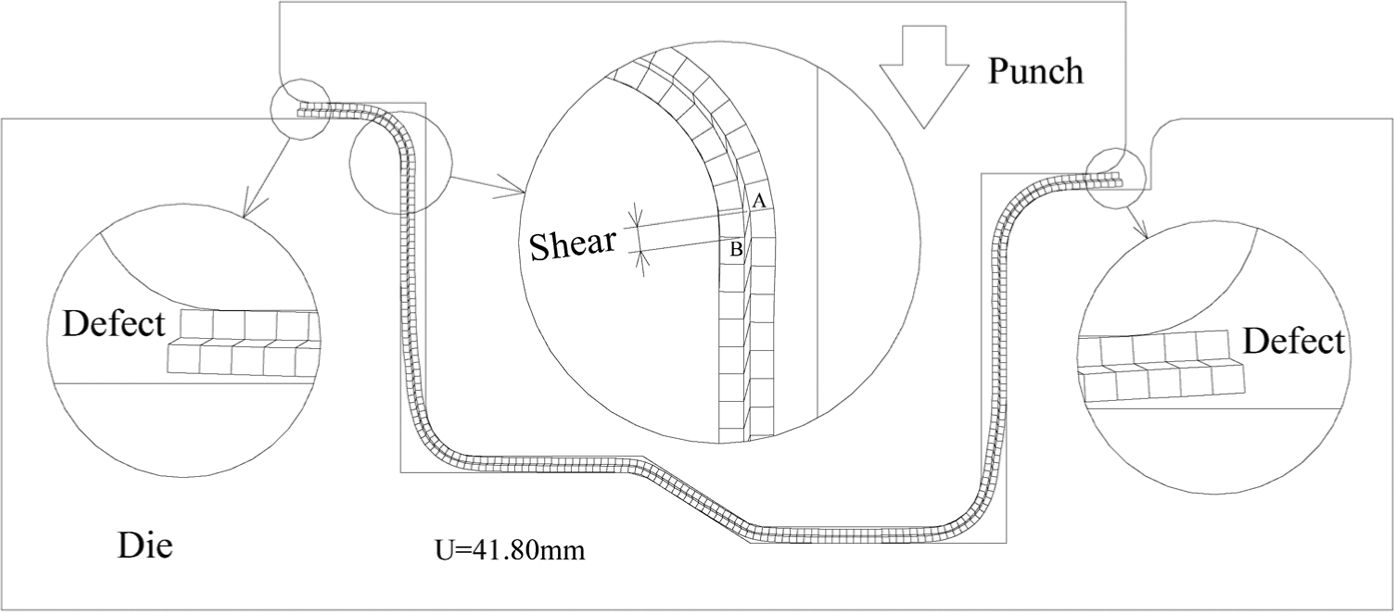
Shear deformation and edge defect in bumper formed from steel/polymer/steel laminate sheet.
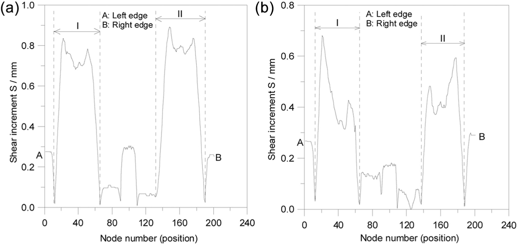
Distribution of shear along the sheet length for (a) CNT and (b) CHT.
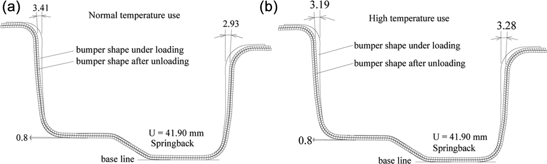
Springback after unloading at final forming stage for (a) CNT and (b) CHT.
Simulation and experimental results for bumper forming using HSS sheet
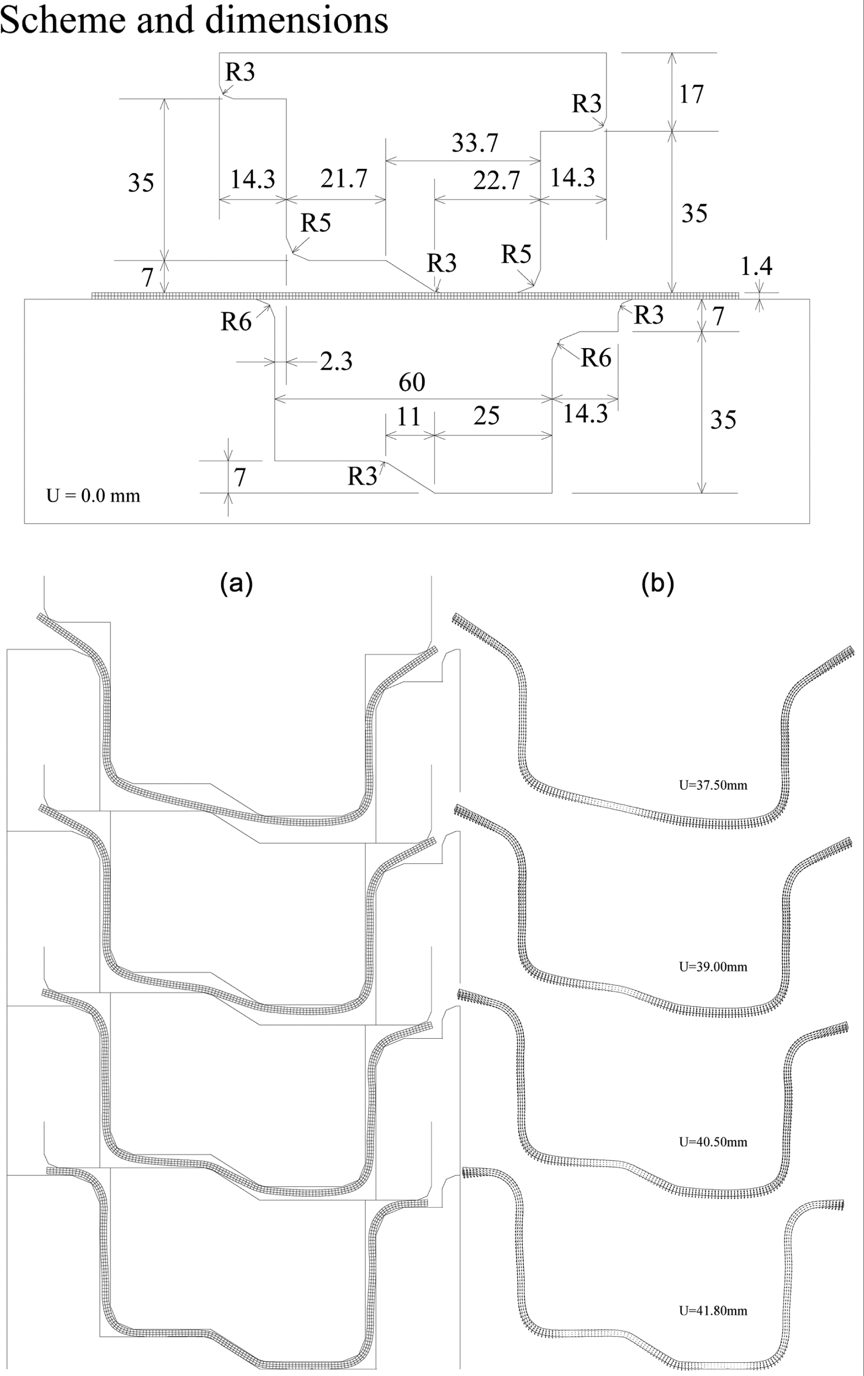
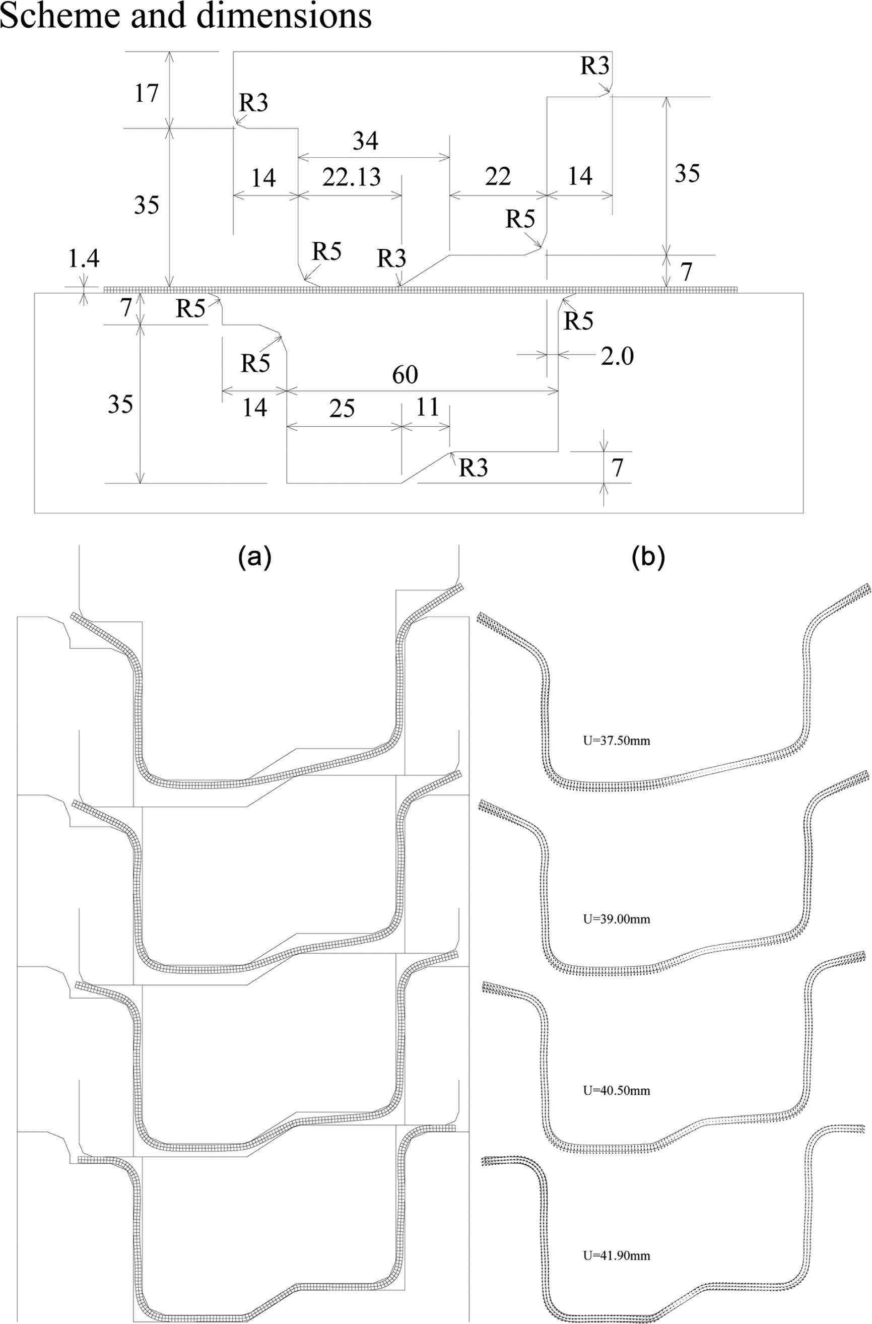
Figure 12 shows deformed geometry distributions at 18 different forming stages of the process for forming bumpers from SPFC 440 HSS sheet with clearance Cr=2.5mm. Figures 13 and 14 also show the deformed shapes and velocity distributions for Cr=2.0 and 2.3mm, respectively, for HSS sheet of SPFC 440. The sheet was bent gradually and streamed smoothly into the die cavity to form a bumper shape without shear deformation or edge defects which will be occurred in laminate sheet. Figure 15 shows the occurrence of springback after unloading at the final forming stage for three cases, which shows the actual bumper shape after manufacture.
Bumper forming processes for M14 sheet with Cr = 2.5 mm.
(a) Deformation shapes and (b) velocity distributions for M14 sheet with Cr = 2.3 mm.
(a) Deformation shapes and (b) velocity distributions for M14 sheet with Cr = 2.0 mm.
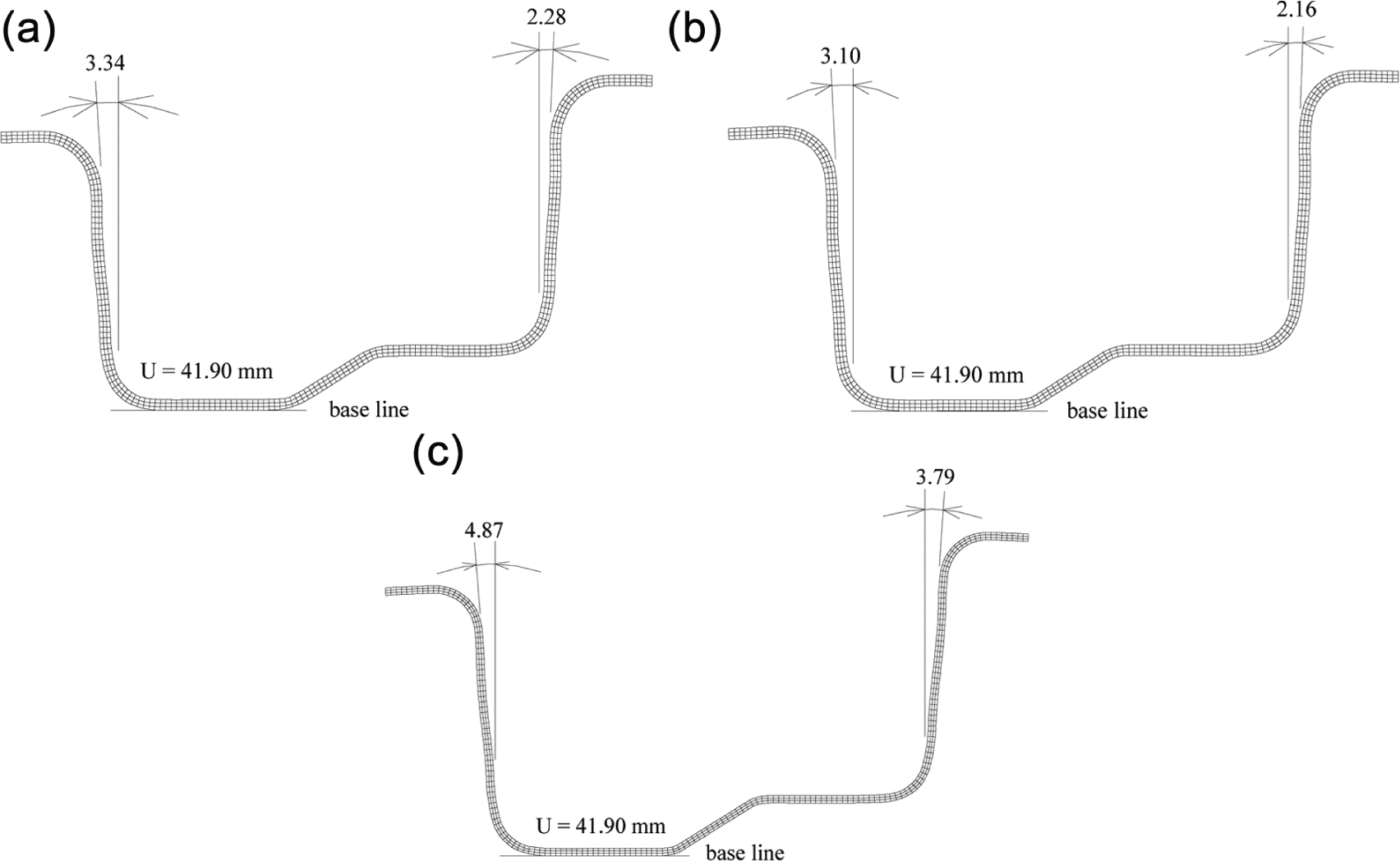
Table 1 shows the material used in a series of experiments performed to explore springback characteristics during bumper forming using HSS SPFC 440 of JIS G3135. A polishing treatment was performed to remove irregularities in the rim of the sheet and to maximize surface smoothness. The two lubricants used in the experiment are WD-40 mineral oil (WD-40) and graphite plus grease (graphite), and the polished steel sheets used in the experiment are prepared by pressing. The experiments were performed with a 300-kN hydraulic test machine. Figure 16(a) shows the experimental layout of the bumper forming process; Figure 16(b) shows the final shape of the bumper after unloading. The experimental procedure was as follows: (1) prepare the blanks and record the dimensions of the blanks, the punch head and the die; (2) set the die assembly onto the hydraulic test machine; (3) smear a thin film of lubricant on the blank and position the blank on the die; (4) set the speed of the punch head used to bend the sheet to 1mm/s; and (5) measure and record the springback angle of the final bumper after unloading. However, a pretest of the lubricating effect showed that the effect of contact friction on springback was negligible because of the very similar springback angle between the WD-40 and graphite lubricants. This implies that the bending constraints have a larger effect compared to friction. Thus, further studies are needed to investigate the interaction between bending constraint and friction resistance.
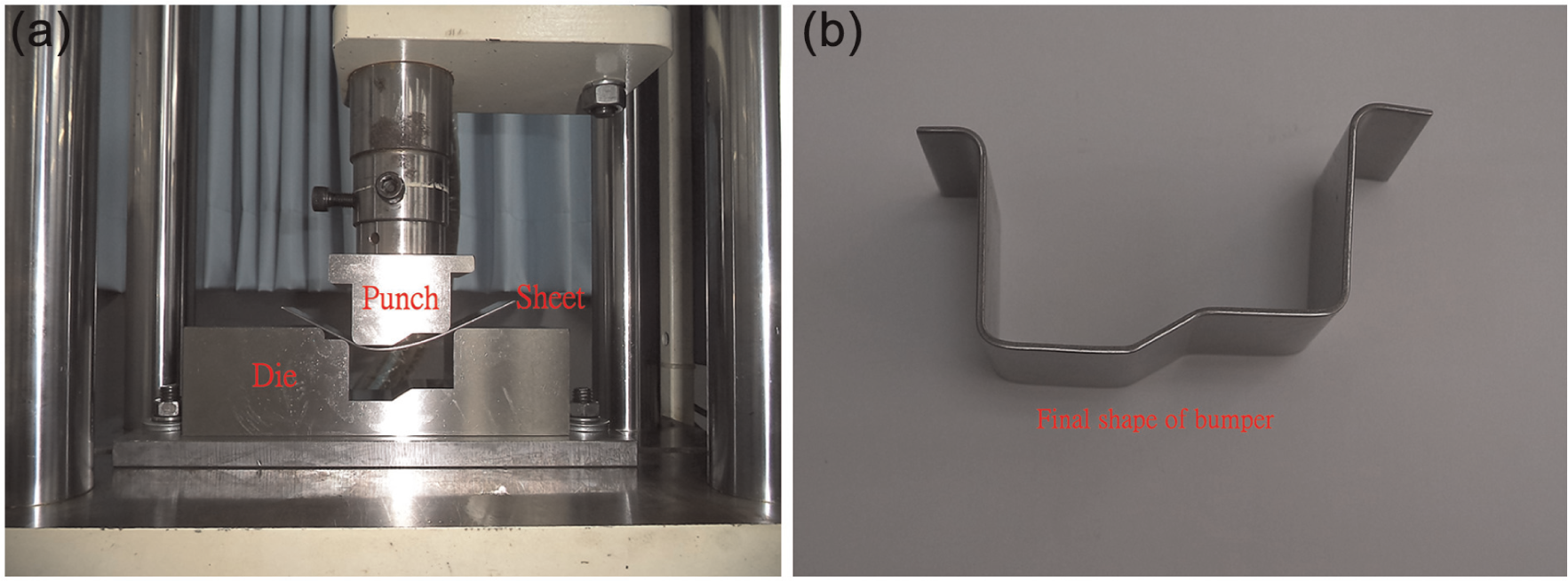
(a) Experimental setup for bumper forming process and (b) bumper shape after unloading.
Table 2 shows the experimental and calculation results for springback angle for the three cases in Figure 15. Based on the values of “Difference” in Table 2, the calculated values agree with the experimental results. On the other hand, the values of “Error” in percentage type seem very large because the values of “Error” are enlarged with percentage type. Errors may occur in simulation and experiment, which may result from inconsistent operations of experiment, irregular properties of material, improper assumptions of condition and inaccurate methods of calculation. However, this comparison emphasized that the FEM is a useful tool for depicting processes and variations in bumper shaping during forming. This method is applicable for numerical simulations of springback phenomena in bumper forming. Moreover, a series of bumper forming experiments were performed to investigate how geometrical process parameters affect springback behavior. Table 3 shows the experimental comparisons of springback angle in several SPFC 440 steel bumpers at clearances of 2.0 and 2.3mm. The experimental results show that the angle correlates negatively with thickness, and the angle of
Difference between experiment and calculation for
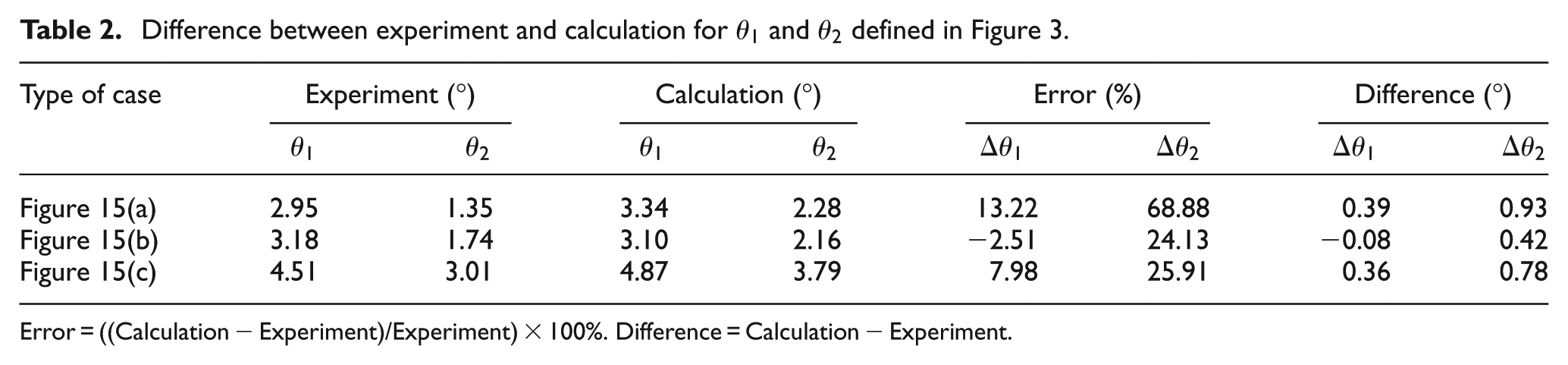
Error = ((Calculation − Experiment)/Experiment)×100%. Difference = Calculation − Experiment.
Results of experimental comparisons of springback angles in bumpers formed from HSS sheet with SPFC 440 at a clearances Cr = 2.0 and 2.3 mm.
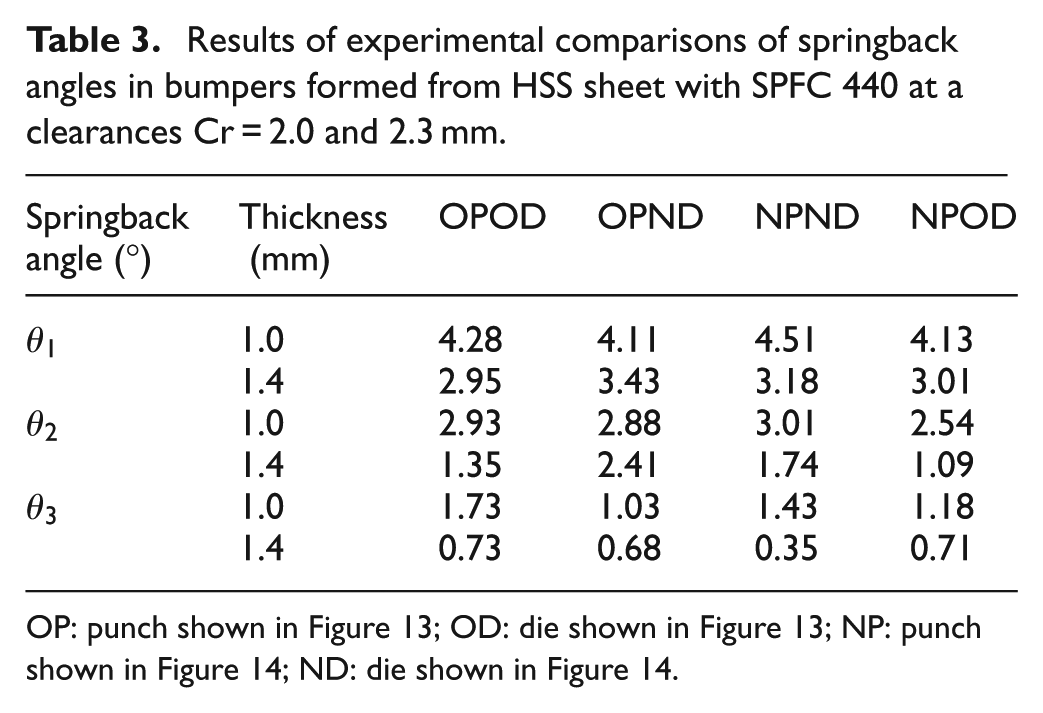
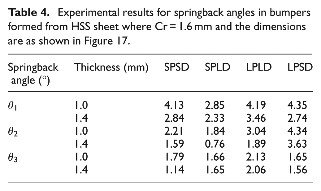
Table 4 shows the results of experimental comparisons of springback angle in several bumper cases under a small clearance Cr=1.6mm. The experimental results are consistent with those in Table 3, that is, the angle is greater in thin material than in thick material; the angle of
Experimental results for springback angles in bumpers formed from HSS sheet where Cr = 1.6mm and the dimensions are as shown in Figure 17.
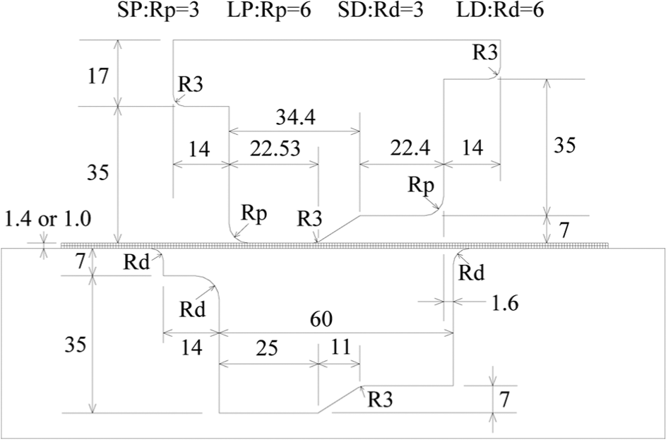
Scheme and dimensions of SP, SD, LP and LD (in mm).
Summary
An elasto-plastic FE model based on an updated Lagrangian formulation is used to simulate punch load, deformation geometries and velocity distribution throughout the process of forming bumpers from HSS and steel/polymer/steel three-layer vibration-damping laminate sheets under a single-stroke operation. The characteristics of bumper forming processes using steel/polymer/steel laminate sheet, for example, shear deformation and edge defect, are simulated and reported in a theoretical manner. The process can be used to manufacture car bumpers with a single-stroke operation. A notable finding of this work is the occurrence of springback, which shows the final shape of the bumper. According to the results of a series of experiments for HSS sheet, the springback angle of a thin material is always greater than that of a thick material; additionally, angle
Footnotes
Acknowledgements
The author thanks Z.L. Yang, J.W. Wu and W.S. Lin for their technical assistance.
Declaration of conflicting interests
The author declares that there is no conflict of interest.
Funding
This research was financially (partially) supported by the Ministry of Science and Technology (National Science Council) of the Republic of China, Taiwan, under Contract No. NSC101-2221-E-149-001.