
Abstract
In this article, an automatic robotic polishing technique and system is developed for the polishing of titanium alloy curved parts. By means of a designed compliant end-effector with a force sensor, the robotic polishing system with a position-based explicit force control architecture is first built to perform the polishing operation. Then, a specially designed multi-axis robotic post-processor based on computer-aided design/computer-aided manufacturing is developed to generate the basic position and posture of the polishing tool without any complicated teaching processes. Subsequently, an adaptive Anti-Saturation Integral Separated Fuzzy PI controller, which is able to imitate the manual polishing operation and prevent undesirable vibrations and mechanical collisions, is designed to control the normal contact force. The basic trajectory is changed each time after the current polishing cycle has been finished by online self-learning, and a new basic trajectory is generated for the next polishing cycle. Finally, the effectiveness of the proposed automatic polishing technique is evaluated by actual polishing experiments on titanium alloy (TC11) parts, and the experimental results show that the proposed automatic robotic polishing technique has a perfect control effect on the contact force and thus can achieve a good and uniform surface quality of the part.
Keywords
Introduction
Titanium alloys have wide applications in the fields of aerospace, energy and power engineering due to their excellent physical and metallurgical properties. For some titanium alloy parts such as aero-engine components, the low surface roughness (Ra < 0.4 µm) and high surface integrity are often required, 1 and thus, the polishing of these parts is a crucial procedure to improve the surface finish and reduce the local stress concentration. However, it is easy to cause surface burning during the polishing process for the poor thermal and chemical properties of titanium alloys. In most cases polishing is done by skilled workers using hand tools, which is very time-consuming and environmentally rugged. Moreover, a casual mistake potentially committed by a worker may result in expensive reworking or even scrapping of the part. Therefore, the automatic polishing of titanium alloy parts is highly desirable but remains challenging due to the difficulties in the construction of compliant end-effector and the accurate control of contact force in polishing.
Up to now, some automatic polishing techniques and systems have been developed to address the problems caused by manual polishing.2–7 Pessoles and Tournier 8 polished the injection mold with mirror finish on a 5-axis machine tool using a passive compliant tool. In the method, trochoidal tool paths are used to cover the surface in a multidirectional way to avoid marks on the part. Huissoon et al. 9 studied the effects of the polishing parameters on the surface roughness of die steel using a flexible abrasive polishing disk. Recently, articulated robots have been increasingly utilized in automatic polishing for their low cost and good opening. Ryuh et al. 10 built an effective robotic die polishing system with an automatic tool changer and realized a completely unmanned operation. Tsai and Huang 11 developed an automatic mold polishing system into which the geometry process kernel, path planner, process planner and force control robot are integrated. The intelligent polishing system can determine the polishing parameters and processes according to the target roughness and the material of the mold. In the path planning of robotic polishing, Tam et al. 12 applied scanning paths to generate the polishing paths and discussed the use of scanning paths to facilitate the realization of continuous polishing. Besides, the robotic polishing process modeling has also been discussed. Liao et al. 13 presented a new approach for modeling and control of an automated polishing/deburring process using a compliant tool head. Márquez et al. 14 built a theoretical polishing evolution model integrated with a control system, so the finishing operations over complex geometry parts were highly automated. Although some automatic polishing systems have been developed instead of manual polishing, the materials to be polished are mainly concentered on the mold steel, aluminum or wood, and the work of automatic polishing for curved titanium alloy parts is limited. Despite that the polishing of titanium alloy parts is involved as shown in Axinte et al., 1 the contact force, as a key factor affecting the polishing quality, was not effectively controlled.
The robotic end-effector plays an important role in the realization of robotic surface polishing. Generally, the robotic end-effector in polishing can be clarified into active and passive categories. The active end-effector is an independent force device in which a closed-loop control scheme is used to measure the contact force that has great effect on the surface roughness. Tsai and Huang 11 proposed an efficient polishing process for precision polishing tasks with an active compliant tool. Lopes and Almeida 15 improved the performance of current commercial industrial robots by using a high-bandwidth force–impedance controlled end-effector. Brecher et al. 16 developed a novel force-controlled orbital polishing head for freeform surface polishing. Instead, the passive end-effector must rely on the compliance of the end-effector itself to maintain a contact force. 10 Some passive end-effectors can also detect the contact force when they incorporate force sensors.13,17 If such an end-effector is applied in the polishing, the contact force will be used as a criterion to modify the tool trajectory. In this case, there is a coupling between the contact force and the robotic motion. An additional displacement of the end-effector is needed to maintain the constant contact force. Generally, both active and passive end-effectors have their own characteristics. The advantages of using an active end-effector include small delay in the force generation and relatively simple control algorithm, but the design and manufacture of the active end-effector are relatively complicated. The passive end-effector with a force sensor has the advantages of executing the task relatively easily, as well as obtaining higher stiffness at a considerably lower weight, but relatively long latency may degrade its performance in surface finishing processes.
When a passive end-effector with a force sensor is used in polishing, the most representative and widely used force control methods are impedance control and hybrid force/position control. Nagata et al. 18 proposed a computer-aided design (CAD)/computer-aided manufacturing (CAM)–based position/force controller for a mold polishing robot. They presented an impedance model following force-controlled method to control the polishing force, and the force was well controlled during the polishing process. Zhan and Yu 19 developed a 3-axis computer numerical control (CNC)–compliant polishing system based on the hybrid force/position control method. The impedance control strategy is unable to control the position and the force separately, so it is not usually used in the accurate control of the force and position. The hybrid force/position control strategy needs to switch between the force control mode and the position control mode frequently, and therefore, to some extent it may decrease the stability of the system. Moreover, both the impedance control and hybrid force/position control strategies need to design specified motion controller. As one of the commonly used force control methods, the position-based explicit control strategy has also aroused attentions since it does not need to redesign the robotic position controller. Pires et al. 20 conducted a deburring experiment on a part with position-based explicit control strategy using a fuzzy PI controller and achieved a good deburring result.
As aforementioned, although the control of the polishing force has been realized in some automatic polishing system, to the authors’ knowledge, the contact force control with an elastic polishing disk tilted relatively to the normal vector of the polished surface has never been reported. Compared with the mounted points, the force-controlled tilted polishing disk is undoubtedly more efficient. Moreover, the burning or over-polishing of the titanium alloy parts could be prevented if the contact force between the tilted disk and the polished surface is effectively controlled. Aiming at realizing the automatic and precise polishing of titanium alloy curved parts, the emphasis of our work is to develop an automatic polishing technique and system for titanium alloy parts using a force-controlled tilted polishing disk.
The remainder of this article is organized as follows: the configuration of the automatic polishing system is addressed in section “System configuration”; both the end-effector design and signal communication are represented in detail. Section “Robotic trajectory generation” describes the generation of the basic robotic polishing trajectory based on CAD/CAM. In Section “Polishing process control,” actual polishing contact forces are calculated considering the gravity compensation, and an adaptive Anti-Saturation Integral Separated Fuzzy PI controller (AISFP) controller is developed. Also, an online trajectory learning method is proposed in this section. Polishing experiments are conducted in section “Experiment.” Finally, some conclusions and future research are given.
System configuration
As shown in Figure 1, the developed automatic robotic polishing system consists of a 6-degree-of-freedom articulated industrial robot, a dedicated robot controller, a motion control card, a specially designed end-effector with a precision force sensor, as well as a computer running Microsoft Windows XP.
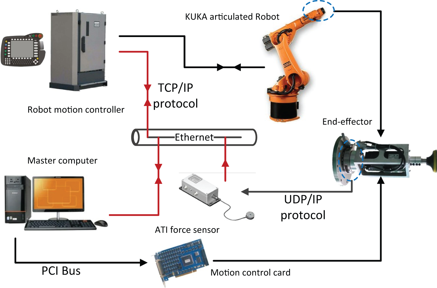
Automatic robotic polishing system developed based on an open architectural industrial robot KR 30-3.
In the system, the used industrial robot KUKA KR 30-3 is an open architectural industrial robot with a control system KR4. It has a payload capacity of 30 kg, a reach of 2033 mm, as well as a repeatability of ±0.06 mm. An ATI Delta force/torque transducer with force ranges of Fx = 0–165 N, Fy = 0–165 N, and Fz = 0–495 N and a resolution of 1/16 N is mounted at the robot wrist to measure the interaction forces. The force data are obtained at a 1000-Hz sampling rate. An average value was calculated for every 10 data points (i.e. 100 data points are obtained and sent out each second). A DMC2210 motion control card is used to accurately control the spindle speed of the tool through peripheral component interconnect (PCI) bus. An Ethernet communication module is set up for both the robot–computer communication and sensor–computer communication. Both the control and communication algorithms are written in C# language. The computer acquires real-time force feedback data from the force sensor and sends displacement commands to the robot controller to modify the position of the end-effector in order to maintain a constant contact force. It is the control center of the automatic polishing system. The proposed system does not need complex tools and jigs, so it can be simply realized.
The end-effector
The designed end-effector for robotic polishing has the following functions: (1) providing enough rotating power for the tools and (2) detecting the real-time polishing force. It is composed of a force sensor, a servo motor with a motor support, a coupling and a polishing tool as shown in Figure 2.
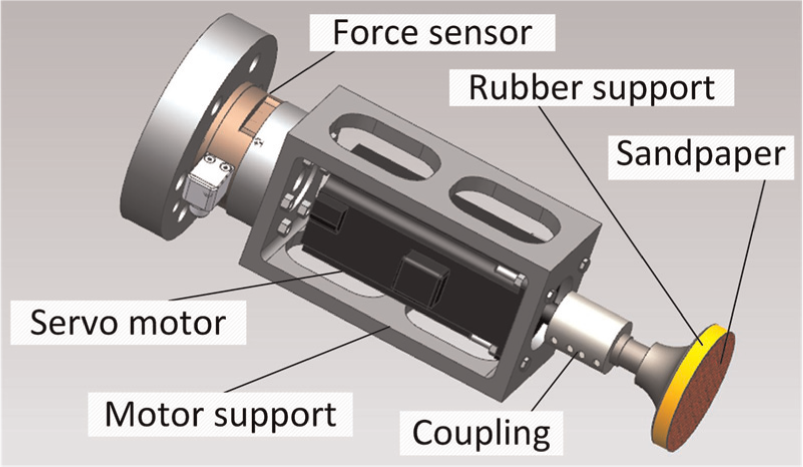
The compliant passive end-effector.
Instead of conventional air-driven method, which cannot detect the rotational velocity accurately and may cause over-polishing easily due to its high speed, an electric servo motor is used to drive the spindle. The rotational velocity of the servo motor can be precisely controlled by the motion control card. The force sensor and the servo motor are connected in series without partial loading. A compliant polishing tool, which is the same as that used in manual polishing, is used here to conduct the polishing process. It is fixed to the motor through a solid coupling. The polishing tool is composed of an elastic rubber support and an abrasive disk. The rubber support is deformable that it not only increases the contact area between the tool and the part but also improves the compliance of the polishing system. The abrasive disk is stuck on the rubber support to perform the polishing process.
Signal communication
The real-time data exchange of the automatic polishing system includes two threads (Figure 3). One is the communication between the computer and the motion controller of the robot, and the other is the data exchange between the computer and the force sensor. Both of the two threads are configured in the same local area network (LAN) via Ethernet in the form of XML strings.
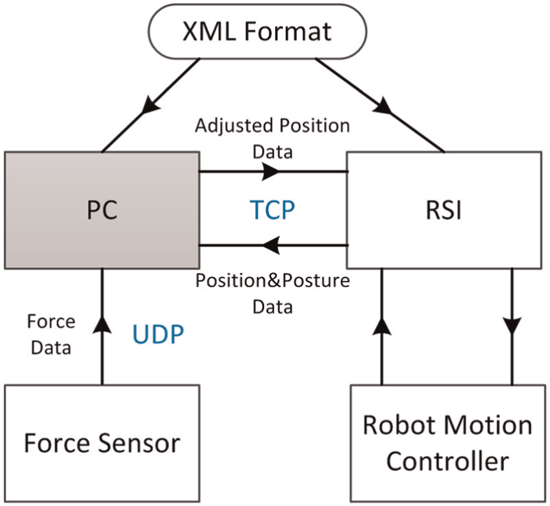
The communication program.
Robot Sensor Interface (RSI) offered by the robot manufacturer is an add-on technology package of KUKA KR30-3 robot. It can realize the configuration of real-time data exchange between the robot controller and an external system via Ethernet. RSI can also influence the robot motion or path planning by means of the data exchange. Here, RSI is used as the transport mediation of the computer–robot communication.
The communication between the computer and the robot motion controller needs good reliability of data transfer. Missing of transfer data may affect the accuracy of motion, the machining precision and the control accuracy of the robotic system. Therefore, the Transport Control Protocol (TCP), which has a relatively high reliability, is chosen as the communication protocol in the robot–computer thread. When signal processing is activated, the robot controller connects to the master computer as a client. The robot controller initiates the cyclical data exchange with a data packet (including Cartesian position data, posture data) and transfers further data packets to the computer in the interpolation cycle of 12 ms. The computer must respond to each arrived data packet with another data packet (including the adjusted displacement data calculated by the AISFP controller) in the same cycle.
To ensure good transport performance of the data exchange, User Datagram Protocol (UDP) is used in the real-time sensor–computer data transport, as minimal transmission overhead is desired to maximize throughput and reliability. The force sensor can output data at up to 1000 Hz over Ethernet using UDP in real time with a cut-off frequency 600 Hz.
Robotic trajectory generation
In the manufacturing industry, most of the curved parts are designed by a CAD/CAM system and manufactured by a multi-axis numerical control (NC) machine tool via a cutter location data (CL data) file. The CL data generated from the CAD/CAM system can also be referred to as the information of the surface shape and be used to generate the basic trajectories of the robotic polishing tool.
Instead of the conventional teaching process, which is extremely time-consuming and complicated for curved surfaces, a specially designed multi-axis robotic post-processor based on CL data is proposed here. The multi-axis robotic post-processor translates the CL data into a robot program format considering the tool length and allows the robot to accomplish the polishing task without any complicated teaching processes. The tool radius set in the CAM software is smaller than the actual tool radius in order to ensure certain contact area between the tool and the part.
The CL data are basically composed of a position vector and a tool axis vector. Then, the kth step of the CL data can be expressed as
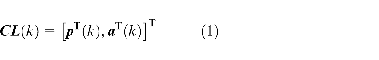
where
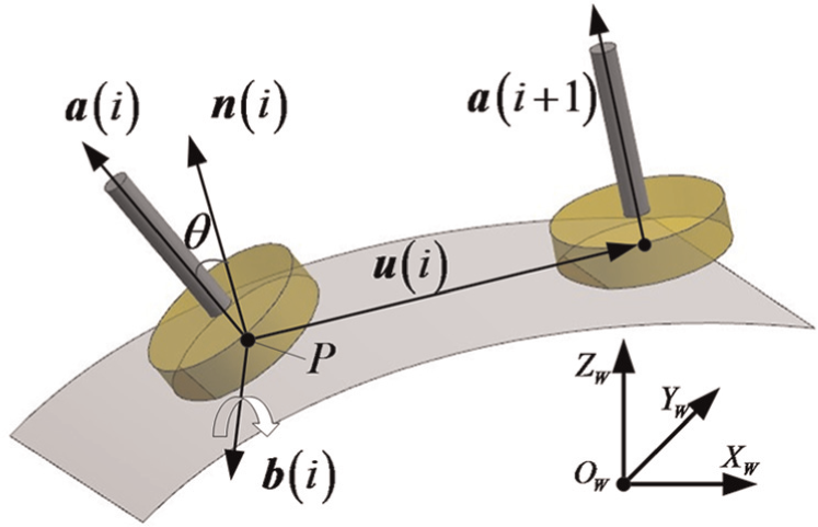
As shown in Figure 4, with the purpose of obtaining a relatively higher linear velocity and achieving a better ability of heat dissipation, the tool axis is tilted relatively to the normal vector in the opposite feed direction at an angle θ. The tilt angle θ is defined as
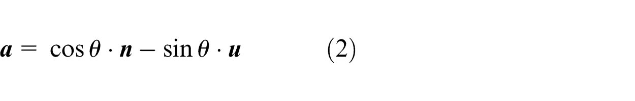
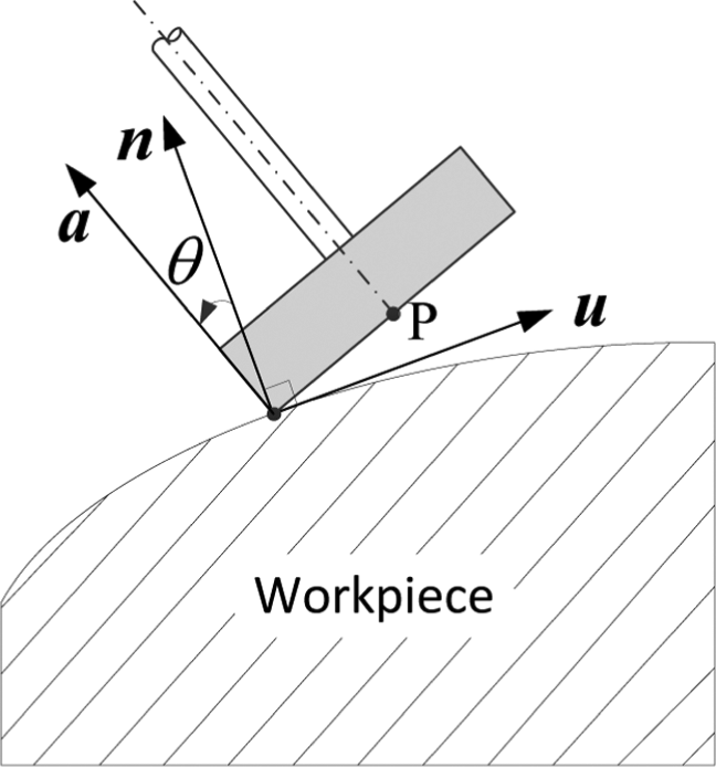
Tilt of the tool axis.
where
The coordinate of the reference point
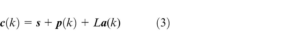
where
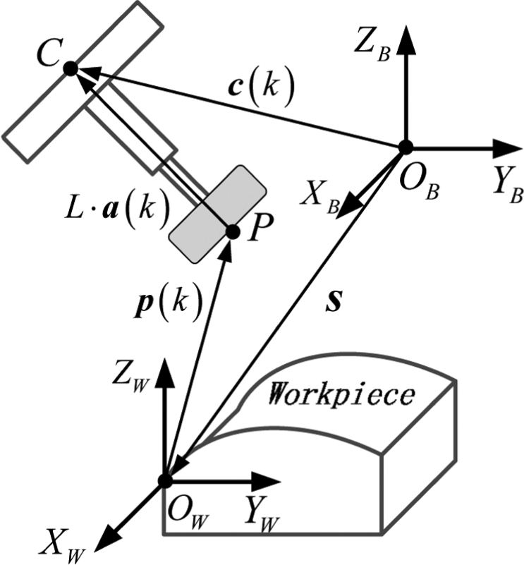
Calculation of the coordinates of reference point.
The posture of the tool is reached from the initial posture according to a specific rotation sequence corresponding to the known roll–pitch–yaw angles, where
Then, as illustrated in Figure 6, the roll and yaw angles can be calculated by
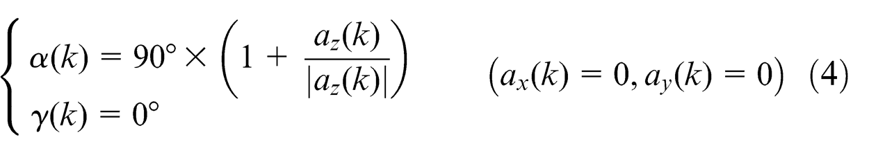
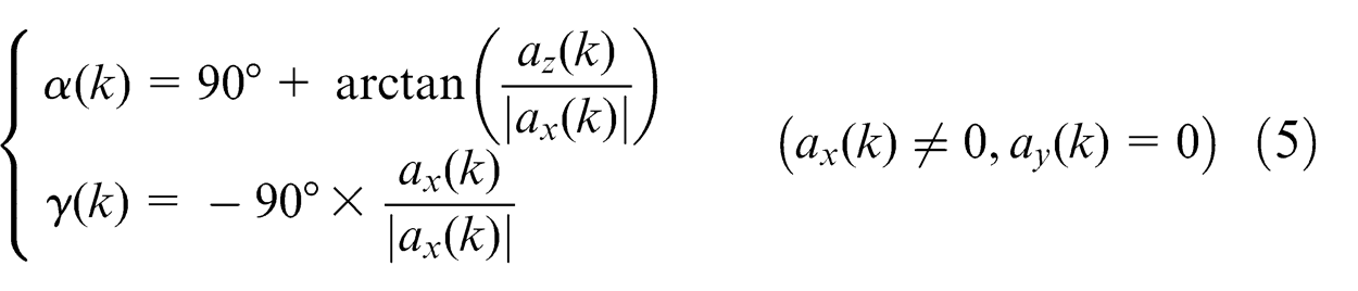
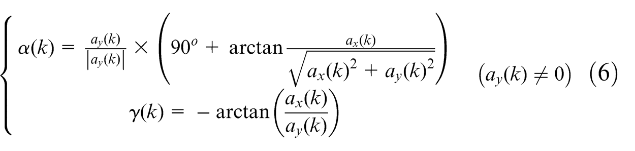
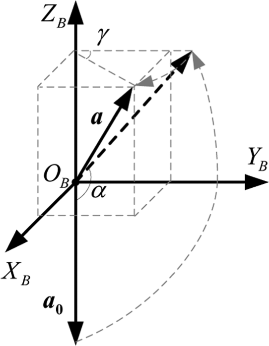
The transformation from tool vector to posture angles.
According to the rules of the KUKA robot language (KRL), the kth line of KRL can be generated as

Finally, the basic multi-axis motions of the robot can be controlled by uploading the KRL program to the robot motion controller.
Polishing process control
Polishing force
From Figure 7, it can be seen that the force measured by the force sensor is composed of the actual contact force and the gravity force of the tool. Therefore, the actual polishing force
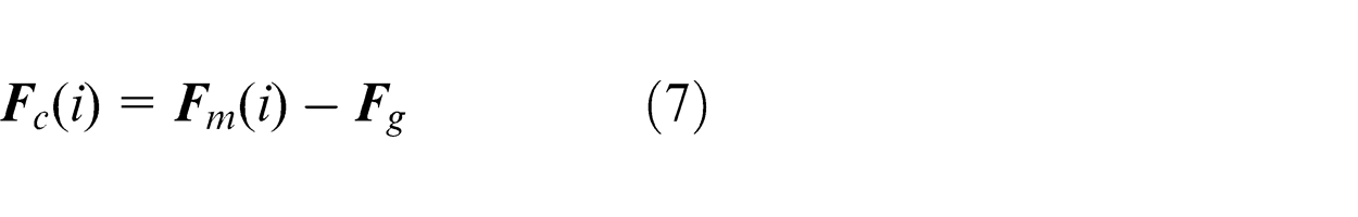
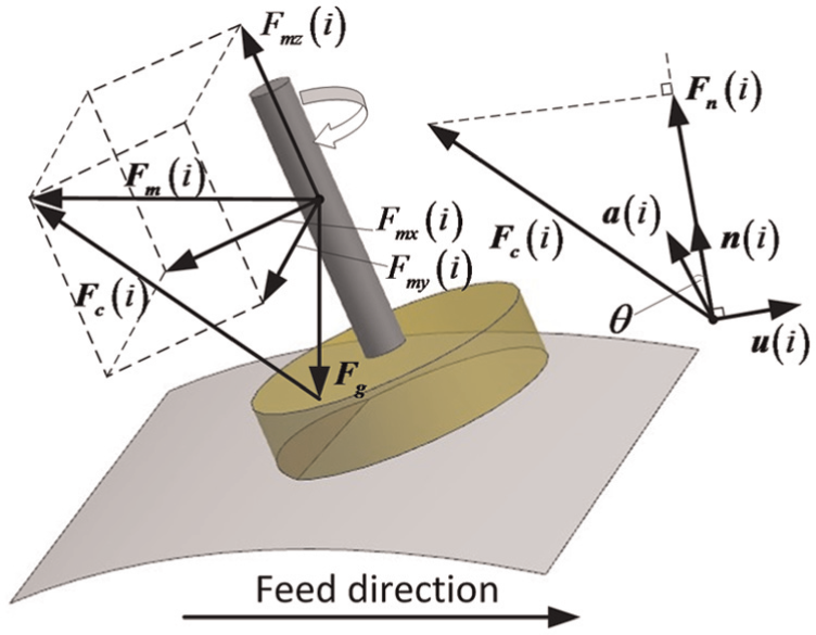
Polishing force analysis.
where i denotes the discrete time.
The average measured force
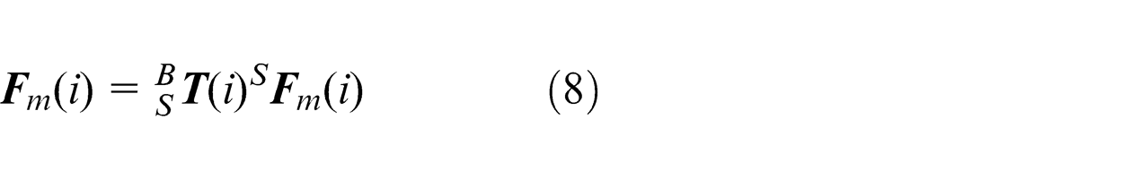
where S
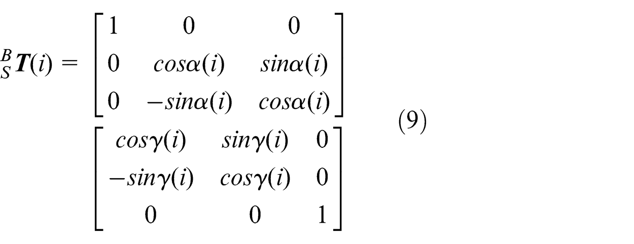
where α(i) and γ(i) are the real-time yaw angle and roll angle, respectively.
Furthermore, it can be simplified as
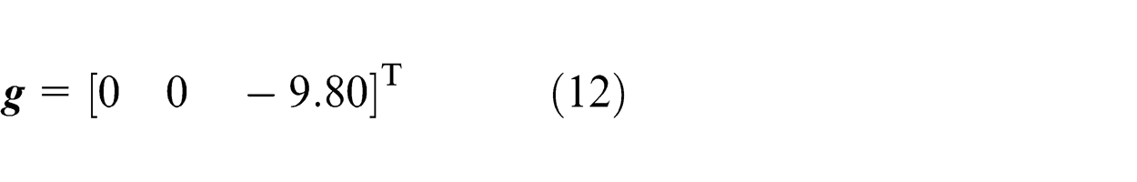
The gravity force of the tool
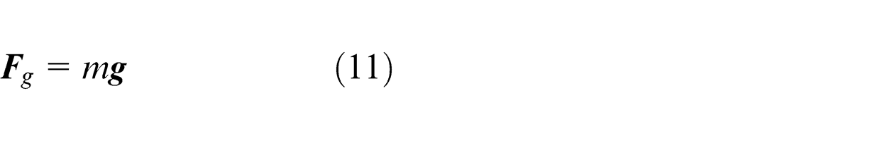
where m is the weight of the tool connected on the tool side of the force sensor.
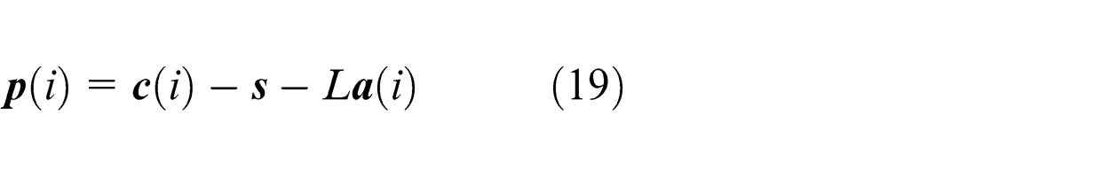
Then, the real-time normal contact force
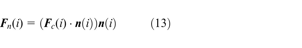
where
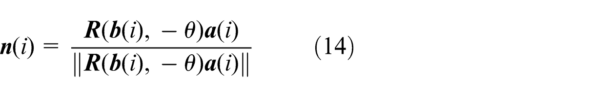
The normalized normal vector to the polished surface.
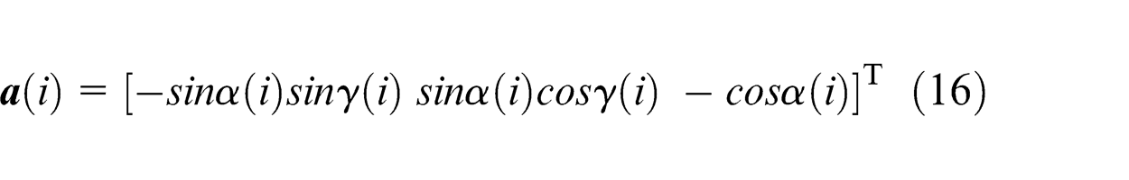
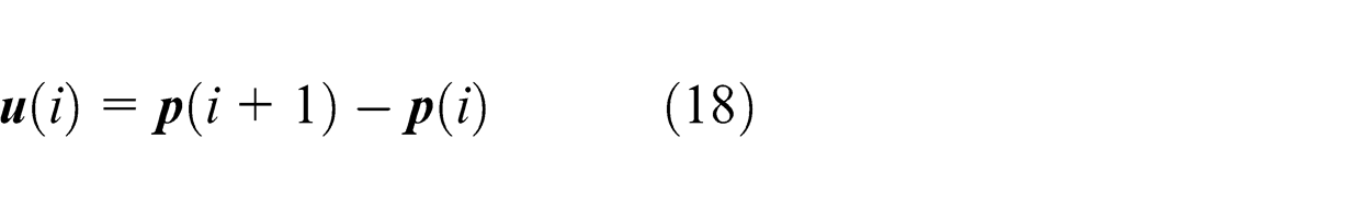
The cutter-axis vector
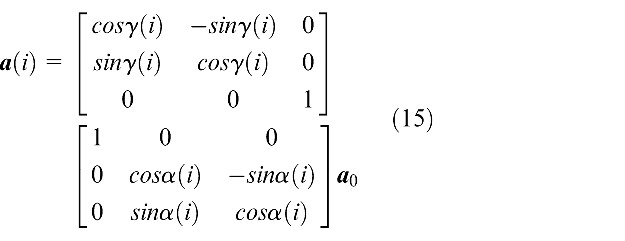
It can be further simplified as
The binormal vector
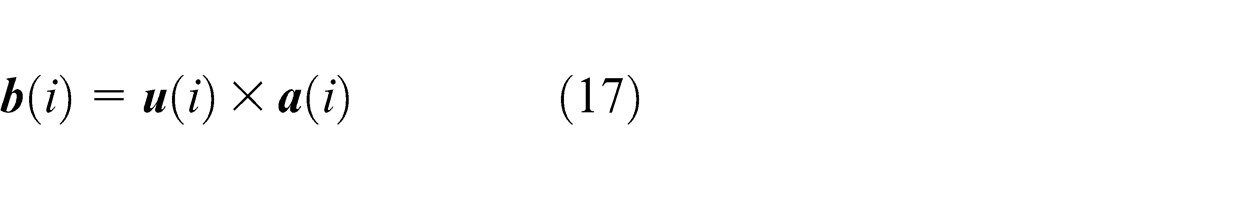
where
and
where
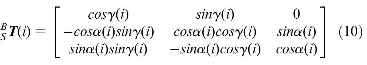
The rotation matrix
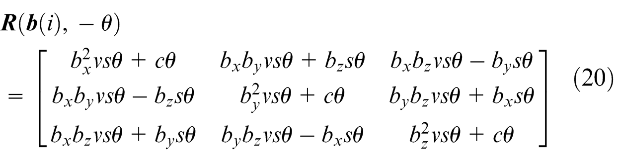
where
Force feedback control
In polishing it is very important to maintain a constant contact force, and only using position control strategy is not enough to polish the parts. Thus, a force control strategy is required to make the robotic polishing disk contact compliantly with the part. Here, the polishing force control was accomplished by a position-based explicit force control architecture consisting of an outer-loop force controller and an inner-loop position controller as shown in Figure 9. In this scheme, the contour-following motion of the mounted polishing tool is controlled by the robot motion controller based on a basic trajectory that was already generated by the multi-axis robotic post-processor given in section “Robotic trajectory generation.” When the tool is in contact with the object, the AISFP controller outputs a real-time adjustment value of the position Δ
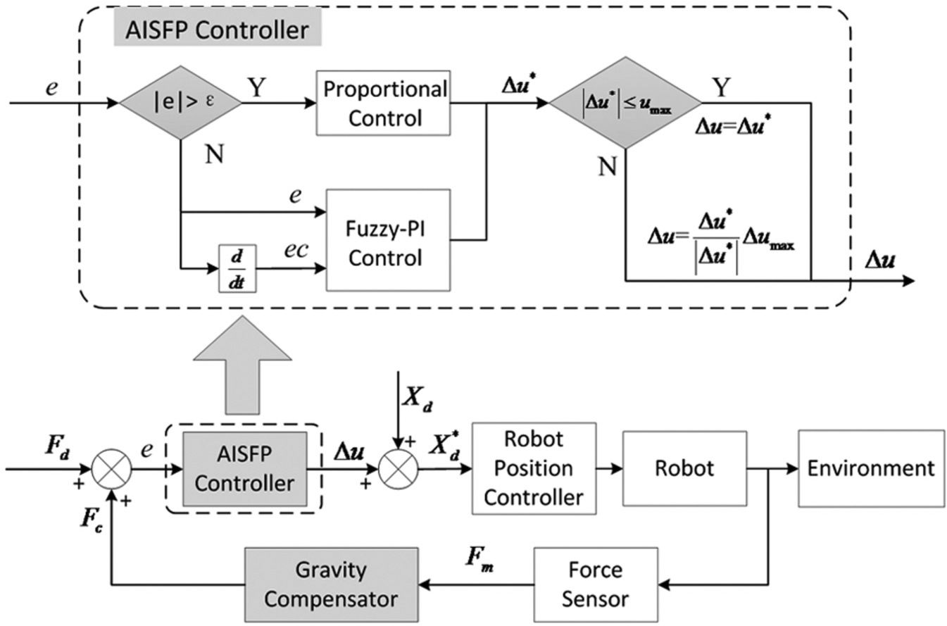
Position-based explicit force controller with an AISFP controller.
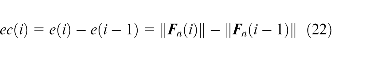
The robotic polishing process has high nonlinearity and uncertainty. For this reason, the polishing force is hard to be modeled and controlled, but skilled workers can accomplish the polishing work with appropriate contact force control. This is because the workers get the fuzzy information of the polishing process with the help of vision and touch, and control the contact force based on prior experiences and judgments. On the basis of the above facts, an adaptive AISFP controller is proposed here (Figure 9). When the error between the theoretical and the actual normal contact force gets large, a proportional control method is used to significantly reduce the overshoot and make the system response fast. When the error is small, another fuzzy PI control method is used to eliminate the static error and improve the adaptability of the system on the environment. The gains of the fuzzy PI force controller are updated in real time on the host computer that estimates the error and error ratio of the contact force and determines the force controller gains accordingly. Moreover, an anti-saturation unit is used to prevent undesirable vibrations and mechanical collisions caused by the large adjustment values of the position. Let Fd denote the theoretical normal contact force, then the error e at discrete time i is defined as
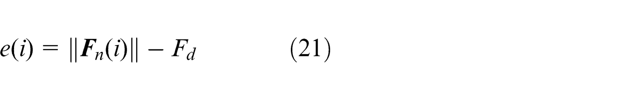
The error ratio can be written as
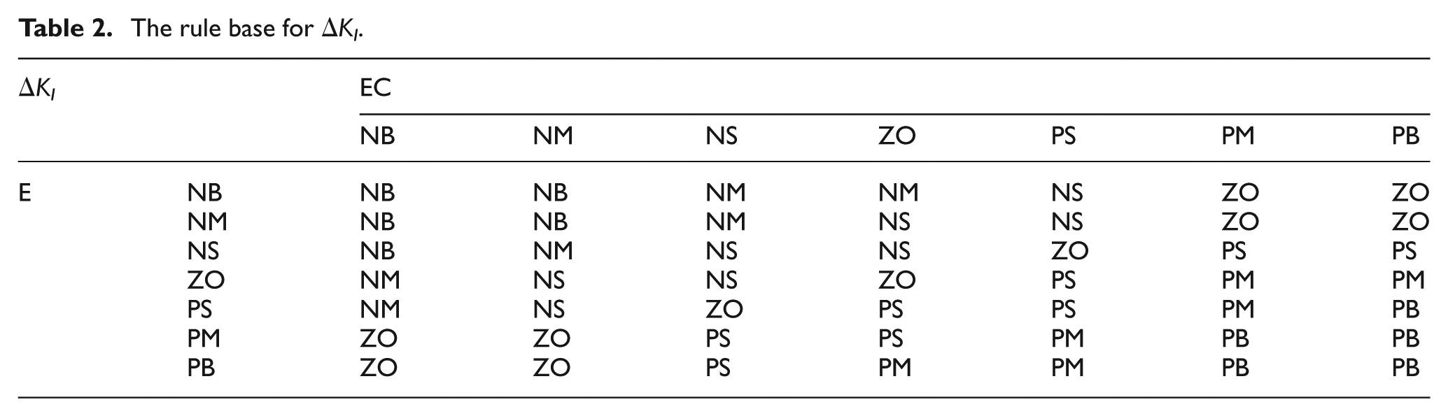
Suppose [−Xe, Xe], [−Xec, Xec], [−YΔKP, YΔKP] and [−YΔKI, YΔKI] are, respectively, the basic domains of e, ec, ΔKP and ΔKI, where ΔKP and ΔKI are the variations of the proportionality gain and the integral gain. Each control variable is normalized into seven linguistic labels: positive big (PB), positive medium (PM), positive small (PS), zero (ZO), negative big (NB), negative medium (NM) and negative small (NS). Both the fuzzy input subset and fuzzy output subset are set as {NB, NM, NS, ZO, PS, PM, PB}. The membership function is used to calculate the membership grade, and the fuzzy subset domain is set as
The most widely used membership functions in the practical applications are triangular membership function and Gaussian membership function. The triangular membership function, whose computation is small, can improve the reaction speed of the system, but it has some effect on system stability. The Gaussian membership function can improve the stability and accuracy of the system, but it has relatively large calculations. To reduce the computation load as well as keep the accuracy and stability of the control performance, the membership functions are selected as shown in Figure 10. The membership functions for inputs e and ec are shown in Figure 10(a), where the triangular membership functions are used with height 1 occurring at points −3, −2, −1, 1, 2 and 3, and the Gaussian membership functions are used with height 1 occurring at point 0. Figure 10(b) illustrates the triangular membership functions for outputs ΔKP and ΔKI.
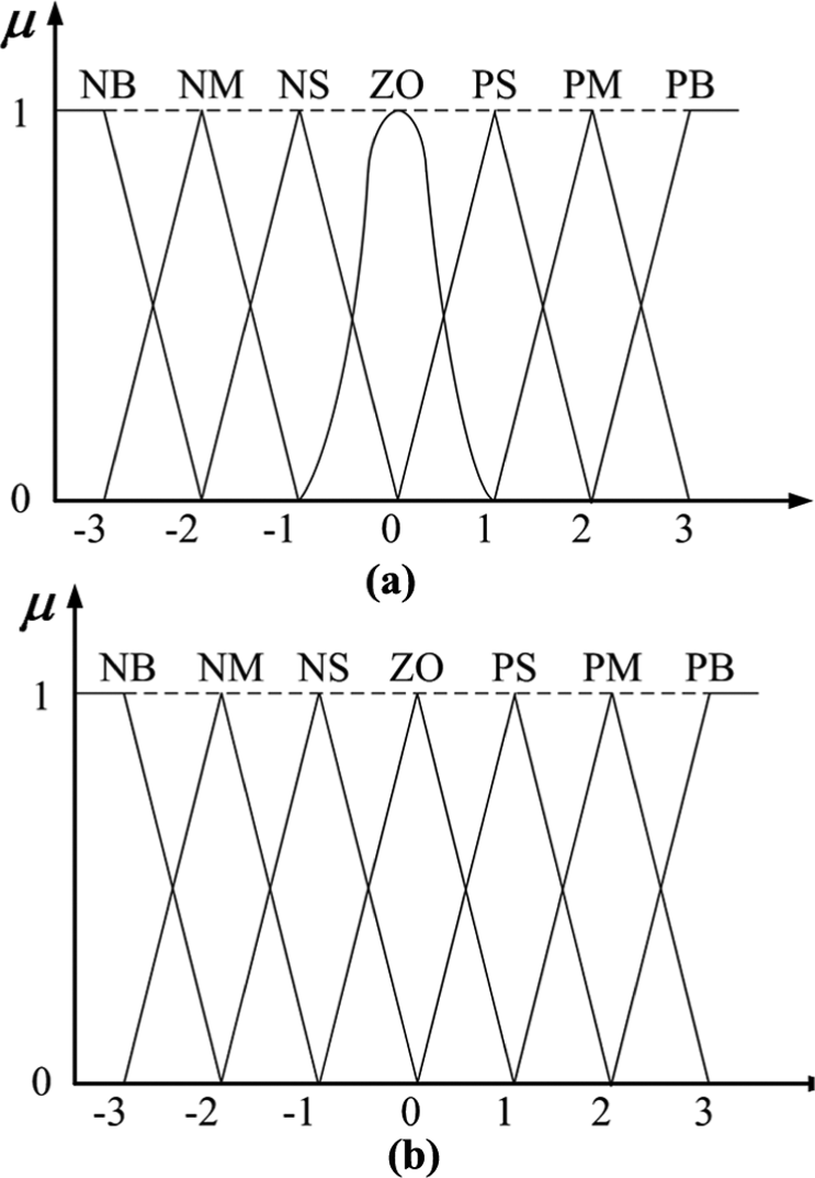
Membership functions: (a) for inputs e and ec and (b) for outputs ΔKP and ΔKI.
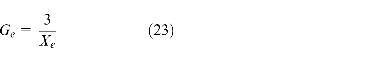
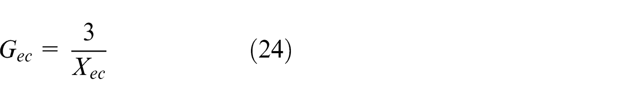
Let Ge and Gec be the quantification factors of e and ec converting from the basic domain to fuzzy domain respectively. Then, Ge and Gec can be computed by
The fuzzy control rules generalize the relationships between the inputs and outputs. They are established based on the experiences and intuitions of the skilled workers. Both the error e and the error ratio ec have seven fuzzy subsets. Therefore, 49 fuzzy rules can be obtained according to the expertise
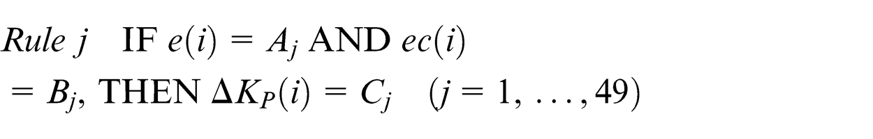
and

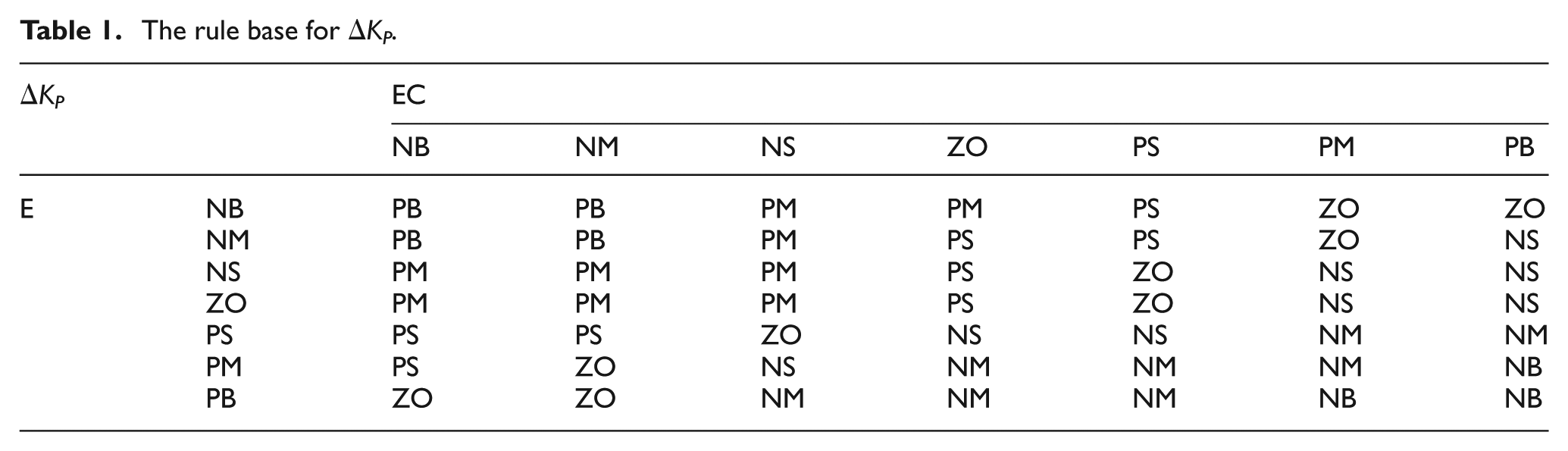
where Aj and Bj are the fuzzy sets corresponding to e(i) and ec(i) in the jth fuzzy rule, respectively, and Cj and Dj are the fuzzy outputs corresponding to ΔKP(i) and ΔKI(i) in the jth fuzzy rule, respectively. The fuzzy rule bases for ΔKP and ΔKI are, respectively, shown in Tables 1 and 2.
The rule base for ΔKP .
The rule base for ΔKI.
The output membership grades for different fuzzy sets are derived from the rule table using the Mamdani fuzzy reasoning method. 21 The center of gravity defuzzification method is selected to defuzzify the output fuzzy set
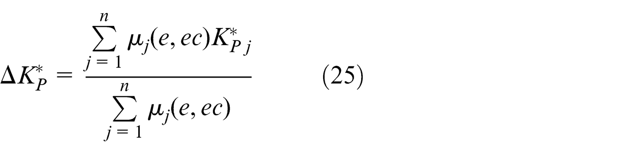
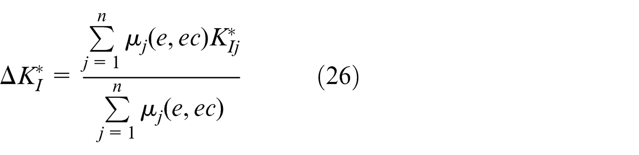
where n is the fuzzy rule number. µj(e, ec) is the membership grade of the jth fuzzy output and takes values in the interval [0,1].
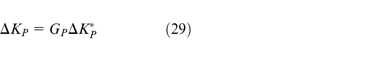
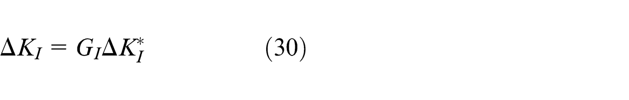
Suppose GP and GI are the quantification factors of ΔKP and ΔKI converting from the fuzzy domain to basic domain respectively. GP and GI can be obtained by
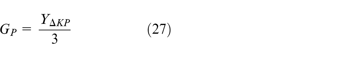
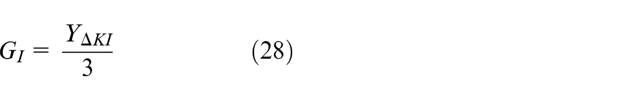
Then, the precise values of
The integral separated fuzzy PI controller could be expressed as
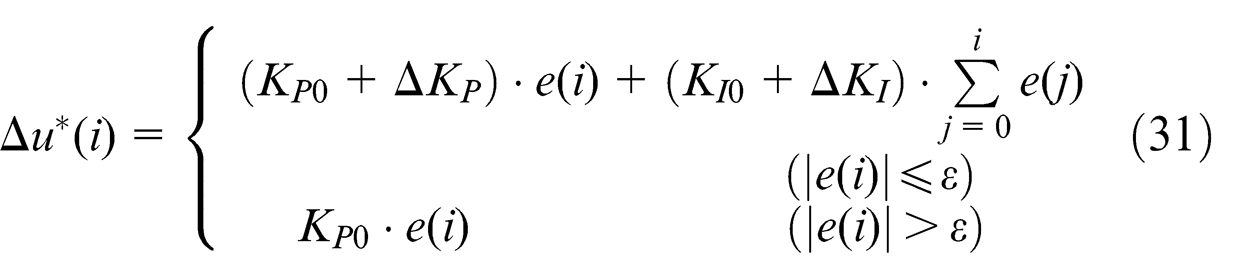
where KP0 and KI0 are the basic values of the proportionality factor and the integral factor, and ε is the integral separated critical value.
Additionally, an anti-saturation unit is added to prevent undesirable vibrations and mechanical collisions caused by the large adjustment values of the position
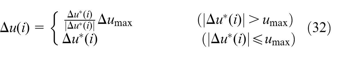
Subsequently, the adjusted value of the position Δ
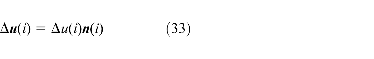
Let
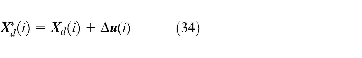
As the polishing force varies, the actual position of the tool is constantly updated using equation (34) in order to keep the normal contact force steady.
Online learning
When the force-controlled robot begins to polish the part using the initial basic trajectory, the actual modified position of the reference point in
For instance (Figure 11), suppose the initial basic trajectory of the reference point is (a)→(b)→(c)→(d). The actual contact force and the nominal contact force are with the same value at point (a), so the tool position does not need to change from the original point (a). At point (b), the actual polishing contact force is smaller than the nominal value; therefore, the AISFP controller outputs a displacement in the opposite direction of the normal vector
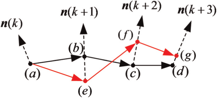
Online learning.
Experiment
Experiment setup
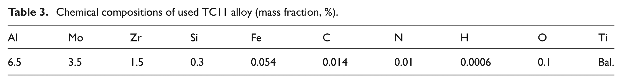
To evaluate the effectiveness of the proposed robotic polishing technique for the polishing of titanium alloy parts, polishing experiments are conducted on both a planar and a curved part. In the experiments, Ti–6.5Al–3.5Mo–1.5Zr–0.3Si alloy (TC11) is selected as the experimental material used for polishing. TC11 titanium alloy is a heat-resisting α + β titanium alloy with good mechanical properties; it is extensively used in the aerospace industry. The chemical compositions of TC11 titanium alloy used in this investigation are given in Table 3. The two sample parts are milled by a 5-axis DMU60 mono BLOCK machine tool before polishing, and have the scallop height of 10 µm after the milling process.
Chemical compositions of used TC11 alloy (mass fraction, %).
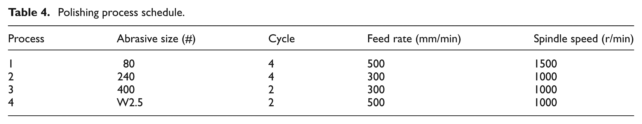
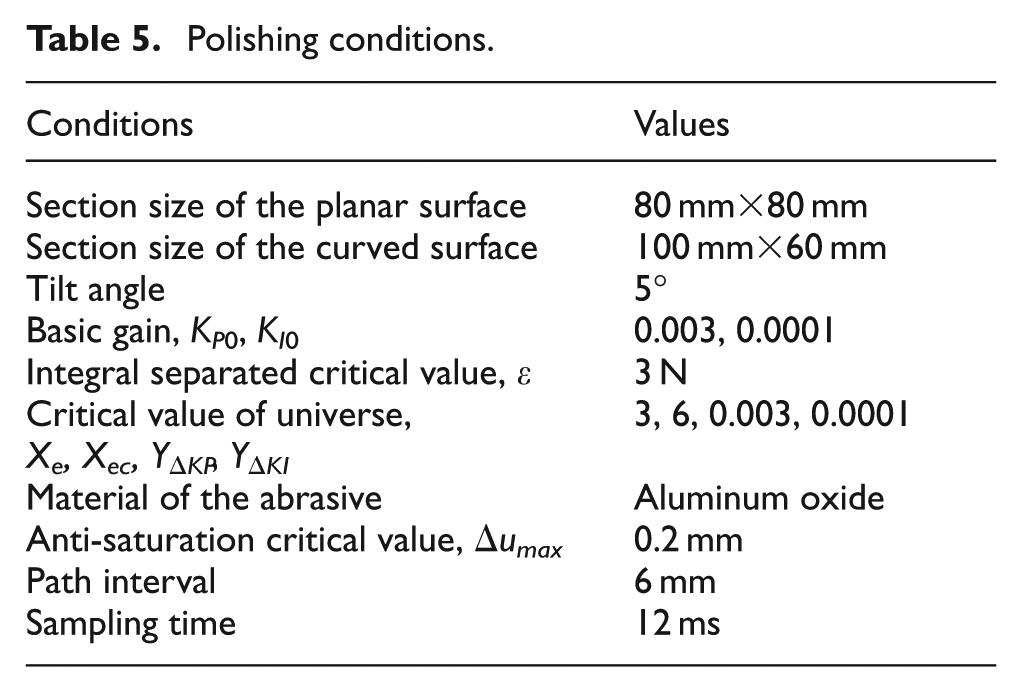
The tool rotates at a relatively low spindle speed to reduce undesirable vibrations that may influence the measured values of the polishing force. Two unidirectional scanning paths were alternately used as the basic trajectories in each polishing cycle as shown in Figure 12. When skilled workers are polishing the parts with such a tool, a contact force from 20 to 40 N is given; here, the nominal contact force is chosen as 20 N. The polishing starts with a rough abrasive disk 80# to remove cusps generated in the milling process. Then, two types of abrasive disks 240# and 400# are used in sequence. For the final polishing stage, the diamond abrasive emulsion (2.5 µm) along with a sponge disk is used with a contact force 10 N to achieve a smoother surface. The polishing sequence is summarized in Table 4. Owing to the relatively low thermal conductivity of titanium alloys, a cutting fluid is used to prevent generating undesirable high temperature in polishing region. Other polishing conditions are illustrated in Table 5.
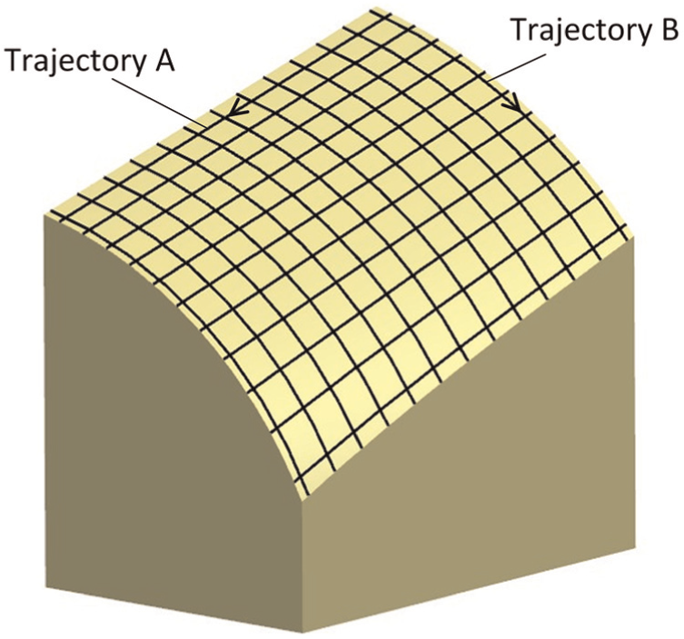
The curved sample part and its polishing paths.
Polishing process schedule.
Polishing conditions.
Results and discussion
The normal contact forces during polishing the curved surface with 80# sandpaper are shown in Figure 13. Figure 13(a) is for the case of polishing the curved part with initial trajectory, and Figure 13(b) is for the case with learned trajectory. From the figures it can be seen that the normal contact force was controlled around 20 N throughout the polishing cycle, and the magnitudes of contact force are not disturbed by the slope and curvature change of the curved surface.
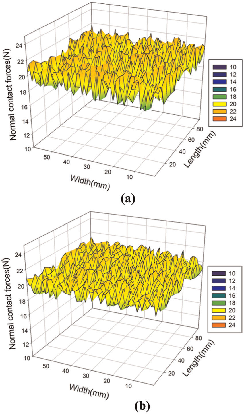
Contact forces for polishing the curved part with 80# sandpaper: (a) using the initial trajectory B and (b) using the learned trajectory B1.
To evaluate the diverge degree between the actual contact forces and the nominal force throughout the polishing cycle, an evaluative variable SF is used with the following expressions
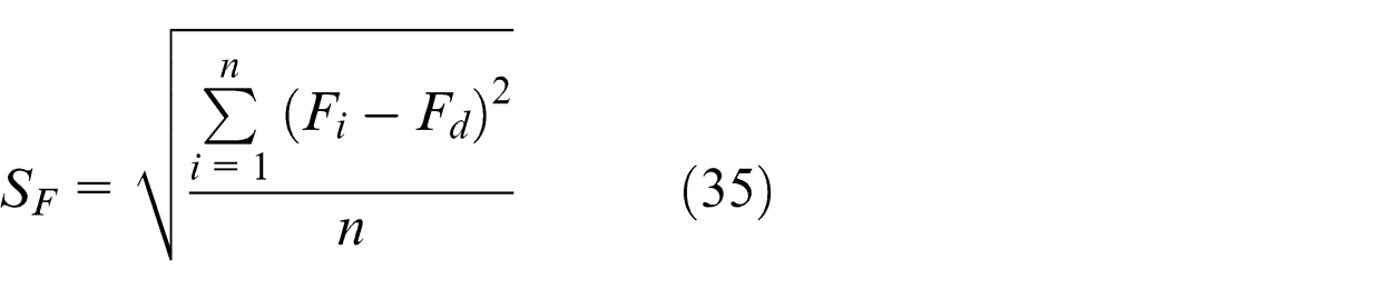
where n is the sum of the force measured points and
According to the above formula, the values of the evaluative variable SF for the two cases are calculated. The value of SF using the learned basic trajectory is SF = 0.755 N, while it is SF = 1.017 N when using the initial trajectory. The comparison results indicate that the fluctuation range of the contact forces becomes smaller owing to the use of the online learning method. Through online learning, the developed automatic robotic polishing system is able to perform the polishing task more uniformly and stably.
The three-dimensional (3D) surface roughness is measured with a non-contact Zygo NewView 5022 3D surface profiler. The measurements are conducted at nine equally distributed positions on the two sample parts, and the averaged surface roughness parameters for the planar surface and curved surface are reported in Tables 6 and 7, respectively. From the table, we can see that for planar part the surface roughness Ra is reduced from 1.707 to 0.135 µm, and for the curved part, it is reduced from 1.750 to 0.207 µm. The improvement rate of the surface roughness for planar and curved surfaces are 92.09% and 88.17% respectively. The proposed automatic polishing technique is proven to be able to satisfy the surface roughness requirement for common-used titanium alloy parts. Figure 14 shows the measurement result at one of the measured positions of the curved surface. Figure 15 shows the results of the final polished curved surface, and from this we can see that a smooth surface is obtained without any undesirable over-polishing or surface burning. The experimental results validate that the proposed automatic polishing technique is effective and can be used to accomplish the polishing of TC11 titanium alloy curved parts.
Surface roughness parameters for the planar surface.
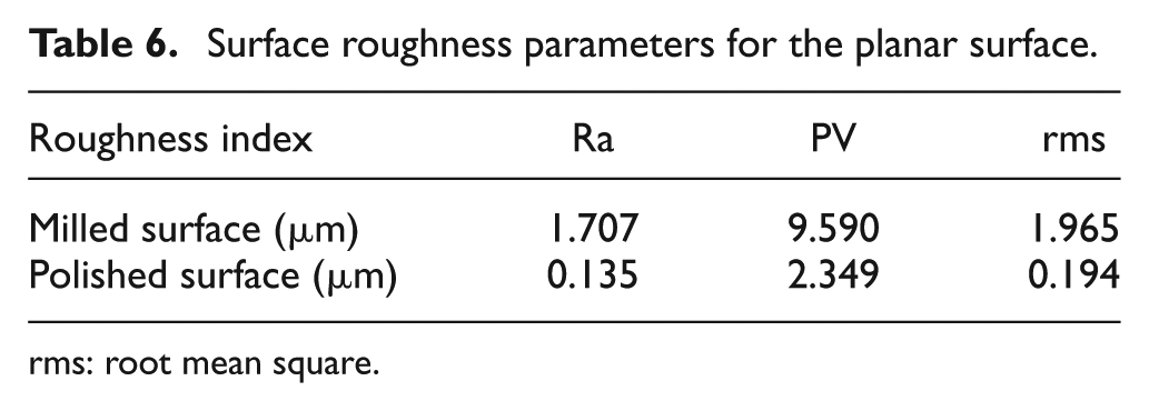
rms: root mean square.
Surface roughness parameters for the curved surface.
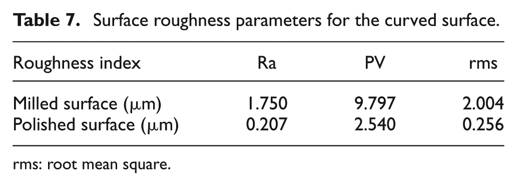
rms: root mean square.
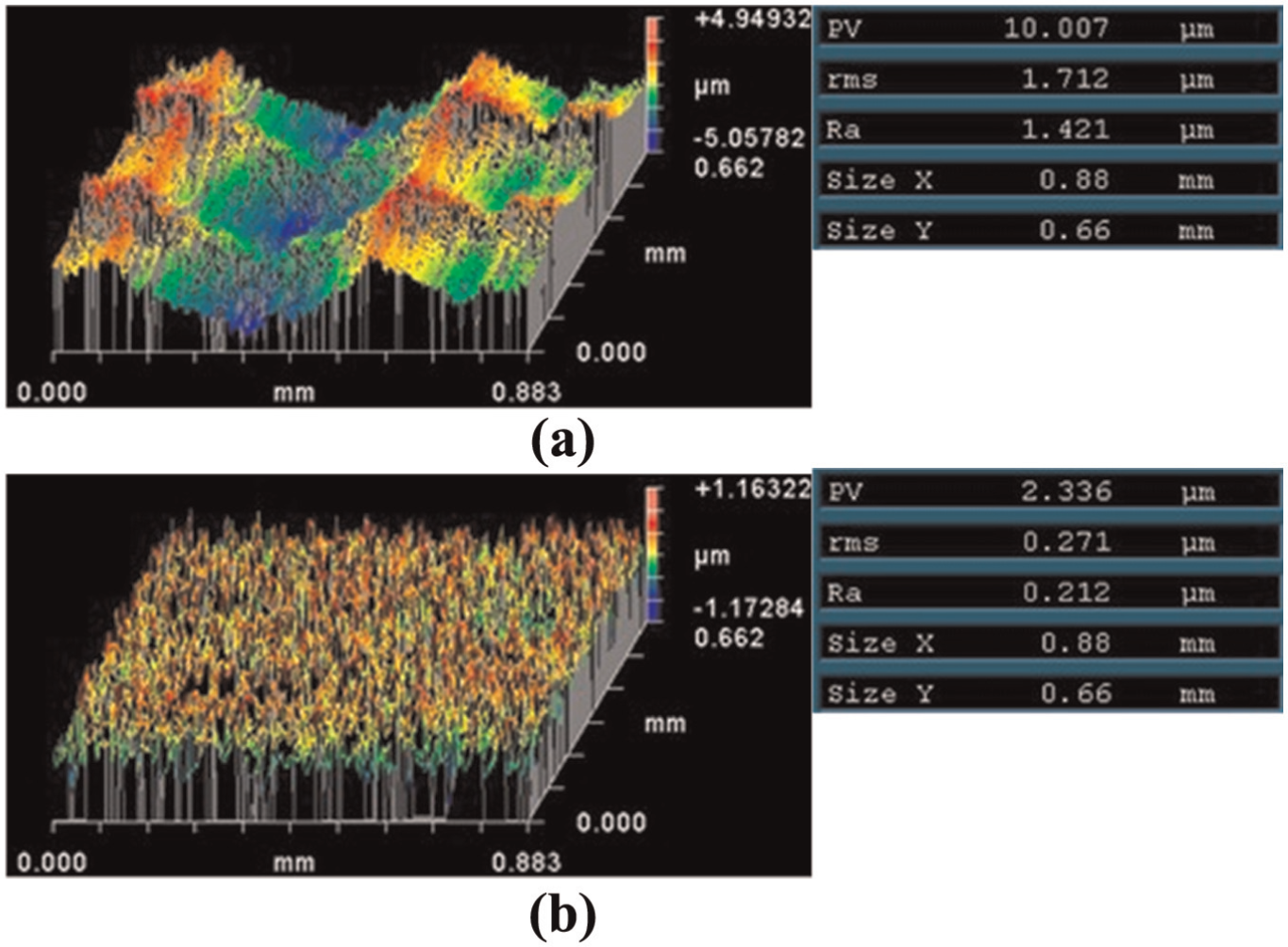
The roughness measurement results at one position of the curved surface: (a) after milling process and (b) after polishing process.
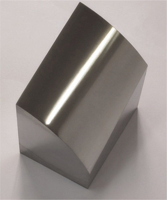
The photo of the polished TC11 curved part.
Conclusion
In this article, an automatic polishing technique and system are developed for titanium alloy parts with a tilted polishing disk. From the research work, the following conclusions can be drawn.
For the automatic polishing of curved parts with a tilted polishing disk, a multi-axis robotic post-processor based on CL data is developed to generate the basic positions and orientations of the disk. The AISFP controller, which is developed under the position-based force control architecture, can imitate the manual polishing process and control the contact force suitably based on fuzzy logics.
Comparisons have been made from the aspect of force control performance between the polishing methods with and without online self-learning. The results show that the online self-learning method is helpful for acquiring a more precise trajectory and improving the force control performance.
Experimental results validate the feasibility and applicability of the developed robotic polishing technique, and it is able to achieve smoother surfaces of titanium alloy parts
In summary, the proposed technique is efficient and effective for the automatic polishing of titanium alloy parts with a tilted polishing disk. Compared with mounted points, it is more suitable for relatively wide curved surfaces. However, both the optimal process parameters and the uniform material removal model still need further research.
Footnotes
Declaration of conflicting interests
The authors declare that there is no conflict of interest.
Funding
This research is supported by National Basic Research Program of China under Grant No. 2011CB706800 and by the Natural Science Foundation of China (NSFC) under Grant Nos 11290143 and 51321004.