
Abstract
For precision mechanical systems, different distribution characteristics of geometric form errors usually lead to different assembly contact states, and in turn, different assembly errors are formed, due to the propagation and accumulation of geometric form errors. Statistically, a batch of part machined by the same precision process possesses the identical distribution characteristics of geometric form errors. It is of great importance to improve assembly accuracy and productivity if the statistic distribution characteristics of geometric form errors can be understood. To solve the problem, two methods of modeling geometric form errors for single parts based on linear combination of basis shapes and modeling statistic geometric form errors for a batch of parts machined by the same process on the basis of principal component analysis are proposed in this article. Besides that, evaluating indicators of model accuracy are also proposed. The results of the case study imply that the two methods can model geometric form errors of single parts and statistically model geometric form errors of a batch of parts, effectively and reliably.
Keywords
Introduction
As well known, machined parts are always not perfect, and it is inevitable that machined parts have errors. The deviation between the real geometric parameters of machined parts, such as geometric dimension, geometric shape and relative position, and the nominal geometric parameters is called machining errors. Machining errors consist of dimension errors, geometric form errors and position errors. In the process of precision assembly, different distributions of geometric form errors of two mating surfaces usually give rise to different contact states, leading to the variation in assembly datum of the assembled parts, and position errors are formed in turn. 1 Furthermore, system assembly errors are produced owing to the propagation and accumulation of geometric form errors. In addition, non-uniform contact states caused by geometric form errors will raise non-uniform stress field in parts definitely. This type of stress field will cause additional errors on the assembly datum, which is different from the geometric errors generated in the process of machining and assembly. Meanwhile, with the change in time, temperature and mechanical environments, the energy of non-uniform stress field will be released because of the rheological behavior of material and structure, which will lead to the variation in assembly accuracy and decrease in assembly stability. Therefore, in order to understand the effects of geometric form errors on assembly accuracy and stability, proper models should be established to characterize the distribution of geometric form errors.
Usually, machining errors are the complex combination of systematic errors and random errors. For precision mating surfaces of precision parts, systematic errors are the main factors influencing systematic accuracy after parts are assembled. Consequently, a batch of parts machined by the same process has statistically identical distribution characteristics of geometric form errors. It is helpful for putting up productivity and reducing production cost, if a statistic geometric form error model characterizing the statistic distribution of parts’ geometric form errors machined by the same process can be established.
In the last 30 years, various methods have been developed to characterize the machined surfaces. Turner 2 proposed a high-order polynomial function to model form tolerance for nominal planar part feature. Wyant and Creath 3 described the functional defects of the lens with Zernike polynomials. Both the methods characterize the machined surfaces directly by polynomial function. The Fourier series was the first used in the decomposition method in order to define periods on circular 4 and linear shapes. For cylindrical surface, Gouskov 5 employed Chebyshev model to define form errors, such as eccentricity and angularity. Henke et al. 6 worked on the geometrical variations in cylindrical surfaces and established an analytical model based on Chebyshev polynomials to model the axial errors and Fourier series to model angular dependencies. Two-dimensional (2D) Fourier was used by Capello and Semeraro7,8 to define the form parameters of rectangular shapes. Kurfess et al. 9 proposed a more universal model, in which complicated deviation was gradually induced on the basis of nominal geometric characteristics, and maximum likelihood test was applied to verify the sufficiency of data description. Serge Samper 10 proposed a new way to define form error parameters based on the eigen-shapes of natural vibrations of surfaces. Huang and Ceglarek 11 used the discrete cosine transform (DCT) to describe rectangular surfaces. A method was introduced by Henke et al. 6 that can evaluate systematic geometric deviations of holes machined by typical processes and reveal the relationships between systematic geometric deviations and process variables. Wang et al. 12 proposed a method to characterize form errors of aluminum parts produced by an extrusion process. Although these approaches can characterize machined surfaces effectively, surface geometric characteristics for only single parts can be described by the methods. However, it is greatly important to statistically characterize geometric surfaces for a sample of measured parts not only for a single one in the real manufacturing process.
A few researchers proposed methods of modeling surface topography. The cross-correlation function of two parallel profiles was used for analysis of lay characteristics by Boudreau and Raja. 13 Tessmer and Kosloff 14 proposed a three-dimensional (3D) numerical Chebyshev modeling scheme to account for surface topography based on spectral derivative operators. Fractal theory was used as a mathematical model for random surface topography by Zahouani et al. 15 Reizer and Pawlus 16 proposed a method to impose a random Gaussian profile on the valley profile and extended the method to model 3D surface topography. Cheung and Lee 17 proposed a method of modeling and simulation of surface topography in ultra-precision diamond turning by a linear mapping of the predicted surface roughness profiles on the surface element of a cross lattice. These methods are suitable to surface topography modeling, but geometric form errors with lower frequency cannot be modeled using these approaches.
This article aims at modeling geometric form errors of planes for precision assembly. It is organized as follows: section “Methodology” shows the approaches to model geometric form errors. A method for modeling geometric form errors of single planes for precision assembly is put forward in section “Models for geometric form errors of single parts,” followed by the evaluation criterion of reconstruction accuracy. Moreover, section “Statistic model for geometric form errors of multiple parts” presents a statistic model which can statistically characterize the geometric form errors of parts machined by the same process and the indicators to evaluate how accurately the statistic model can describe statistic distribution characteristics of geometric form errors. Section “Case study” gives two case studies to illustrate how to apply the methods proposed in section “Methodology.” Conclusion is drawn in section “Conclusion.”
Some basic definitions are given as follows for convenience:
Model of plane geometric form errors for
Statistic model of plane geometric form errors for multiple parts (SMMP) is defined as a model that can statistically reveal the distribution characteristics of plane geometric form errors of a batch of parts machined by the same process.
Methodology
The method proposed in this article depends on the data of planes measured by a coordinate measuring machine (CMM). The data used to establish SMMP should be measured by the same CMM and be sampled at identical sampling frequency to guarantee the accuracy of models.
Models for geometric form errors of single parts
Geometric form error decomposition
Coordinate values of sampling points can describe geometric features of parts. However, the number of sampling points is limited. If geometric features were described by limited sampling points, the main features of geometric form errors would be extracted on the basis of coordinate values of sampling points. The nature of feature extraction is to characterize high-dimension space using low-dimension space by the method of mapping. Mapped features is called further feature, and it is the combination of original features. Shape features can be represented as the combination of nominal features and minor correction functions. Correction function can be represented as
Assume that a measured surface is represented as a column vector
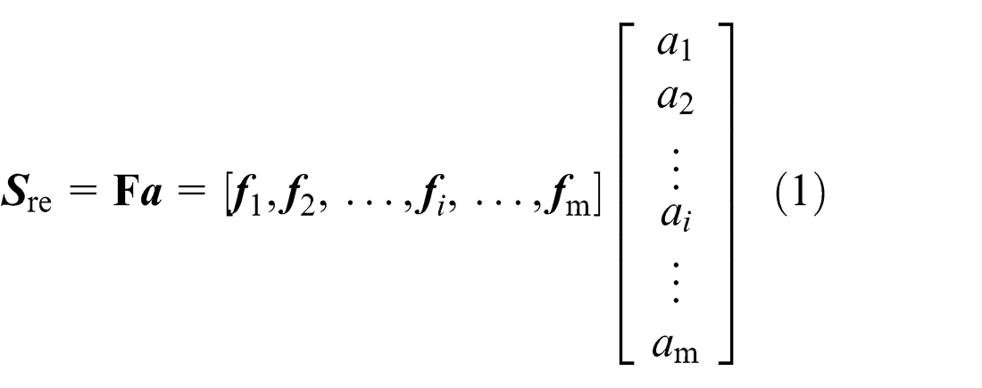
where
Determination of basis functions
Reconstruction plane is the linear combination of basis functions, thus basis functions should be orthogonal to each other. The nature of Fourier transform is inner product, and trigonometric function is the complete set of orthogonal function, namely, the inner product between trigonometric functions with different frequencies is 0. Consequently, trigonometric functions generated by Fourier transform are orthogonal to each other, and they can be considered as basis functions. Nonetheless, form error modeling aims at real number field, while Fourier transform is in the range of complex regime. Therefore, kernel function of 2D DCT is considered here, which can be transformed in the real number field.
Kernel function g(m, n, u, v) is represented as follows
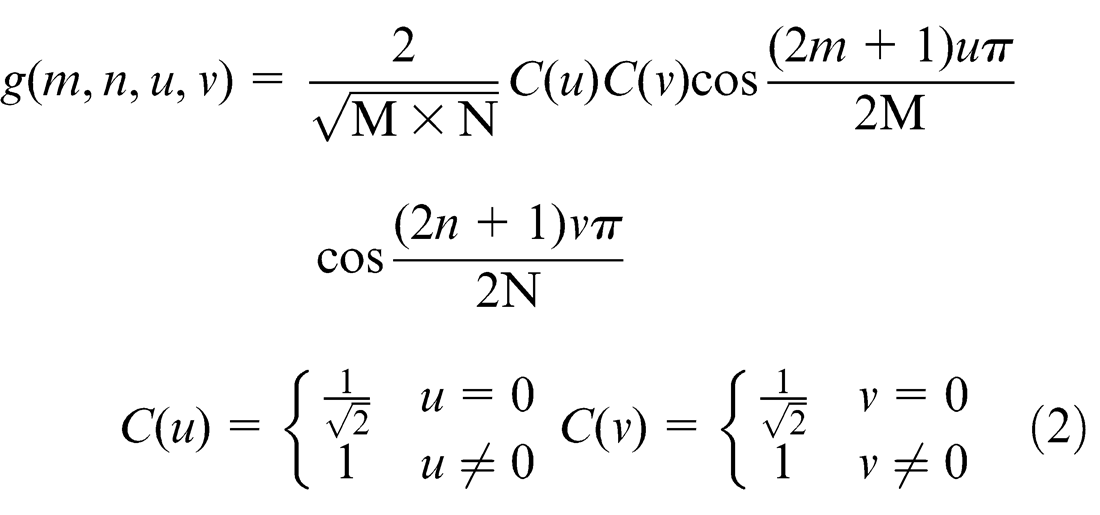
where m, u = 0, 1, …, M − 1 and n, v = 0, 1, …, N − 1. m and n represent the number of sampling points. M and N represent sampling size. u and v are the frequency variables.
Any two vectors of kernel function matrix of DCT are orthonormal to each other
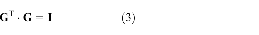
where
Kernel function set of DCT is a set of orthonormal vectors, which can be used as basis function of geometric form error model. Moreover, basis shapes corresponding to basis functions and error sources in the manufacturing process are closely related, so it is quite reasonable to use the weighting of basis functions to reconstruct plane geometric form errors. In equation (3),
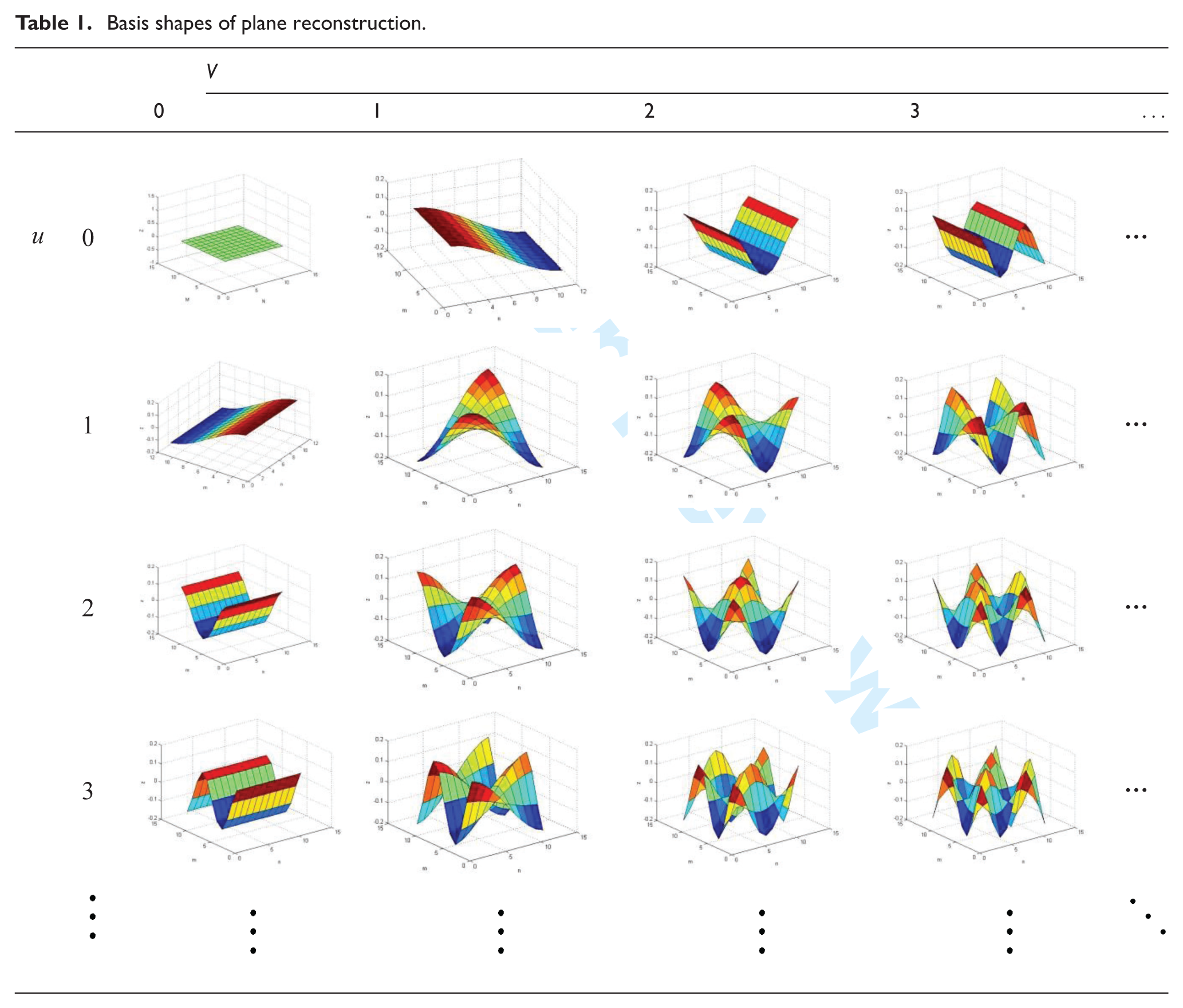
Basis shapes of plane reconstruction.
Determination of coefficients
To guarantee that the reconstruction plane
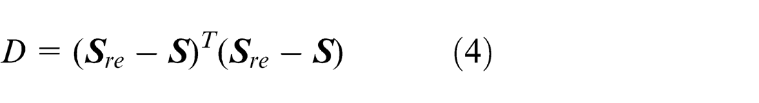
In order to obtain optimal solution, take the derivative of D with respect to the vector
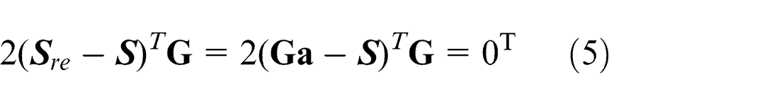
Taking transpose gives
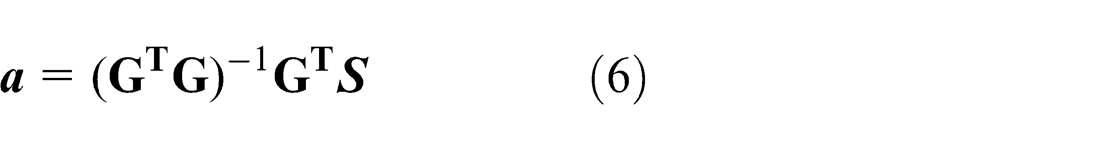
Substituting equation (3) into equation (6) gives
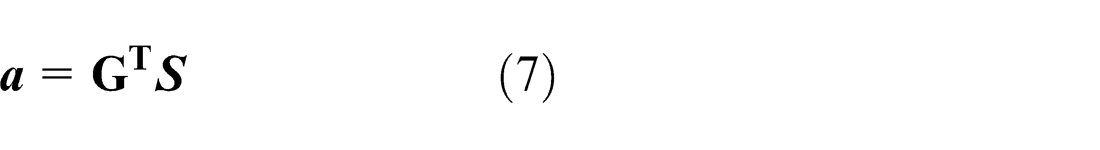
Equation (7) implies that vector
Plane reconstruction and evaluation of reconstruction accuracy
Depending on the definition of MSP, modeling plane geometric form errors of single parts is to reconstruct the plane using as few parameters as possible. Basis function matrix
To evaluate the difference between a reconstruction plane and a measured plane, an evaluating indicator, reconstruction error of reconstruction planes, is proposed. It is defined as
where zi
is the height value of ith measured point on the measured plane;
Reconstruction error can reveal the absolute error of models, but machining errors of measured planes are also small. Therefore, the ratio of reconstruction errors and machining errors of measured planes is also considered as an evaluating indicator of reconstruction planes. It is defined as reconstruction error ratio.
Reconstruction error ratio is represented as
where
Statistic model for geometric form errors of multiple parts
Establishing SMMP
A batch of parts made of the same material and machined by the same process ordinarily possess the identical tolerance value. Furthermore, distribution characteristics of geometric form errors of these parts are similar to each other. Mastering geometric form error distribution will do much to analyze error sources and optimize assembly process to receive the highest assembly accuracy, especially for precision and ultra-precision systems. An approach to modeling statistic distribution characteristics of geometric form errors will be proposed in this section.
To establish SMMP, the most important is to extract the common features of plane geometric form errors from all the planes using mathematical statistics method. Principal component analysis (PCA) is a method utilizing the concept of dimension reduction to find out several comprehensive variables that can contain as much information as the original variables do to replace so many original variables, without relativity between the new comprehensive variables. The main idea is to gain the principal components (eigenvectors) and the corresponding weighting values (eigenvalues) through eigen decomposition. Taking all the measured planes as original data, the common features of geometric form errors can be achieved by means of descending dimension to extract the main data information.
For example, m parts are processed by the same techniques and n fixed sampling points are set on each part, and then, the matrix
where
The following approach can be applied to solve matrices
And then,
where
Define equation (15) as follows
Each element in
After derivation, matrix
In turn, equation (17) can be obtained
Combined with equation (11), it can be gained that
Note that detailed deviation is in Boudreau and Raja. 13
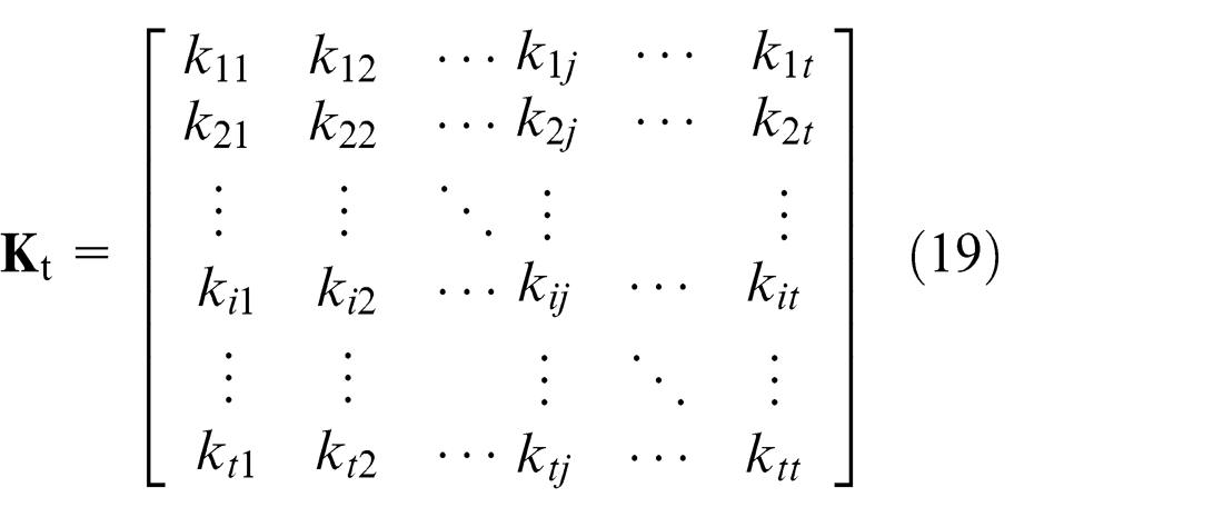
Diagonalization gives common features matrix
Selected t common features are represented as matrix
The mean value of all the elements in each row of matrix
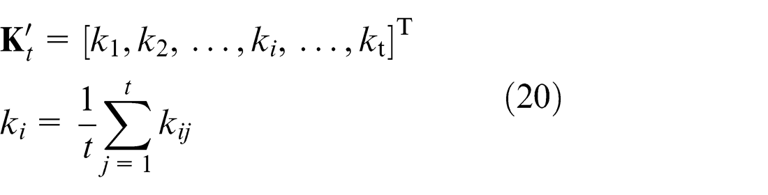
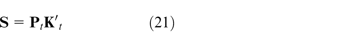
So far, SMMP can be represented as the linear combination of t common features by matrix
Evaluation of SMMP
To evaluate whether SMMP can accurately describe statistic distribution characteristics of geometric form errors of parts machined by the same process, an indicator, characterization errors, is put forward. Characterization errors of SMMP with respect to the lth measured plane can be represented as
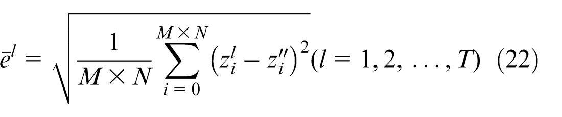
where
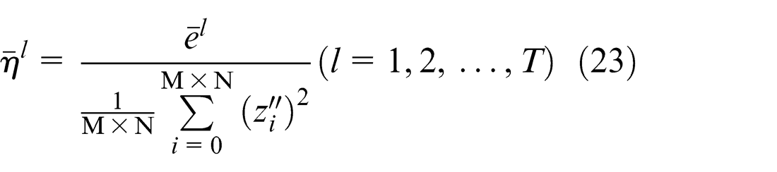
Accordingly, the characterization error ratio of SMMP with respect to the lth measured plane can be defined as
Case study
To validate the modeling method proposed in this article, 10 parts are machined by disc-mill tool of numerical control (NC) machine tool, model VMC850B, using end milling. The size and material of all the planes are 5 cm × 5 cm and 45 steel, respectively. All the parts are finish milled after roughly milled. After machined, the parts are measured by CMM, model PMM12106C. Measurement uncertainty of the CMM is (0.6 ±l/600) μm, which is far smaller than machining errors and can be ignored. For measurements, the parts are located in a simple 3-2-1 fixture. The probe is moving along the measured plane row by row and is gathering data in the interval of 5 mm. Hence, there are 11 rows and 11 columns of sampling points on each measured plane, and then 121 sampling points in total. In Figure 1, 10 milling planes based on measurement data are plotted.
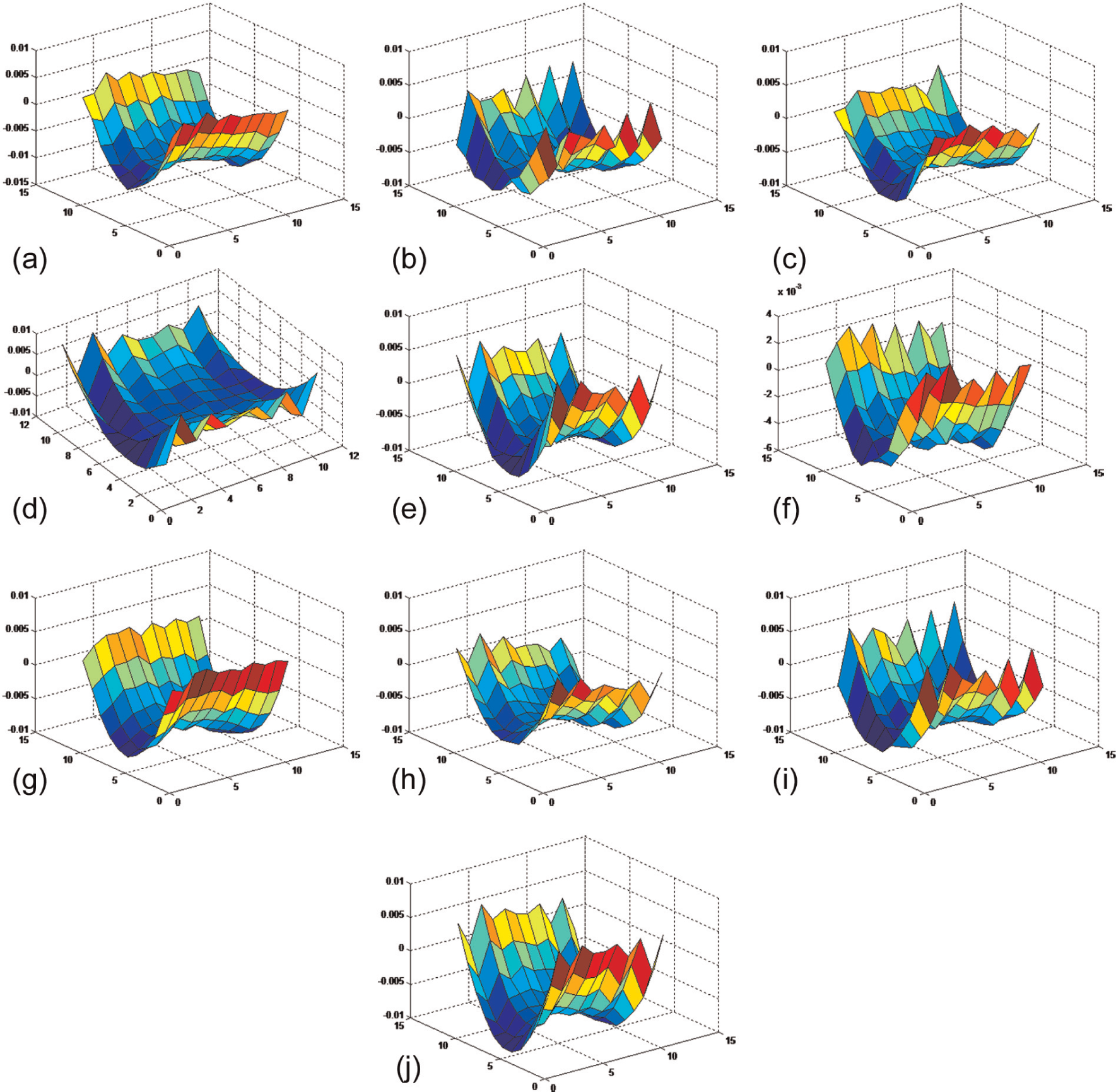
Geometric form errors of milling planes: (a) plane 1, (b) plane 2, (c) plane 3, (d) plane 4, (e) plane 5, (f) plane 6, (g) plane 7, (h) plane 8, (i) plane 9 and (j) plane 10.
Modeling geometric form errors of single parts
According to the sampling size, 11 rows and 11 columns, 11 × 11 combinations (u, v) can be determined, and 121 basis functions can be obtained. Due to space limitations, only the first 16 basis shapes are shown in Table 1.
Taking plane 1, for example, depending on basis functions and measuring data, reconstruction coefficients and reconstruction plane of plane 1 can be realized and shown in Figures 2 and 3, respectively.
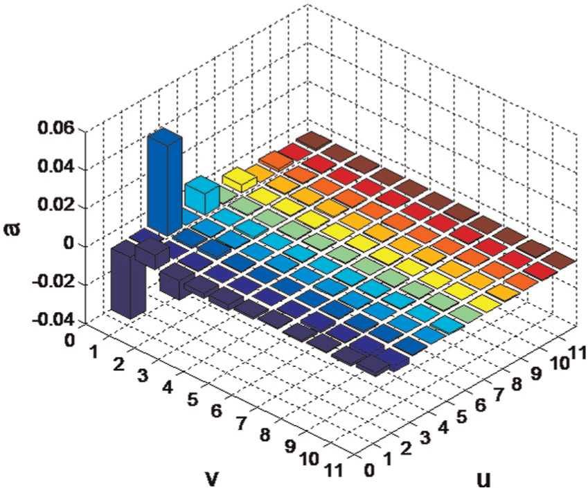
Reconstruction coefficients of plane 1.
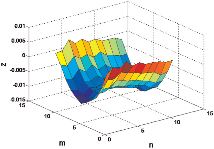
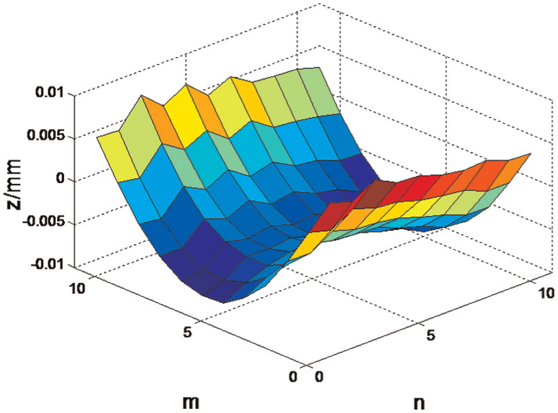
Reconstruction plane of plane 1.
Reconstruction error e1 of plane 1 is 1.3053e−17 mm and corresponding reconstruction error ratio η1 is 2.3908e−15. It indicates that the reconstruction accuracy is greatly high, applying linear combination of basis functions to perform plane reconstruction. However, M × N basis functions should be calculated in order to reconstruct planes. The calculation complexity will be increased if the sample size is very large. The coefficient matrix
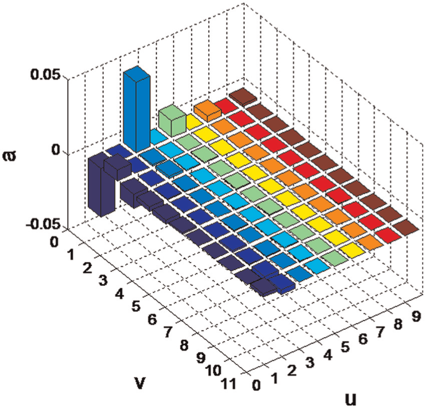
Reconstruction coefficients of measured plane 1.
Reconstruction plane of measured plane 1.
The reconstruction error and reconstruction error ratio of the 10 planes are shown in Table 2.
Reconstruction error and reconstruction error ratio.
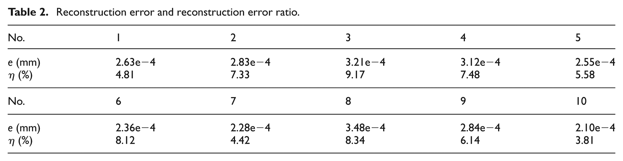
Table 2 suggests that reconstruction errors are only micron scale, and the ratios of reconstruction errors are all less than 10%. The reconstruction planes are accurate enough, and only 30 basis functions are selected here, which means each reconstruction plane is described by 30 parameters. Compared with 121 measured points on the original plane, MSP can describe the plane using fewer parameters.
To illustrate the outperformance of the method, comparison of this method and other methods is conducted. Table 3 gives the results of a comparison with the method based on modal analysis proposed by Samper and Formosa, 10 taking the 10 planes for example. For ensuring the two methods can be compared in the same condition, 121 nodes are established when the modal analysis is performed and 30 eigen-shapes most contributing to the plane characteristics are selected as basis.
Comparison results of 10 planes’ reconstruction.
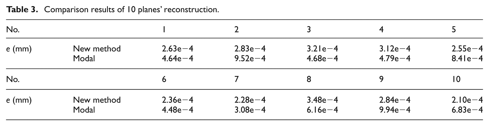
The comparison results show that the method proposed in this article can reconstruct planes more accurately with the same number of basis. To further compare the two methods, gradually increasing the number of basis will be taken to reconstruct plane 1 using the two methods. The comparison results of reconstruction errors will be presented in Table 4.
Comparison results with different number of basis.
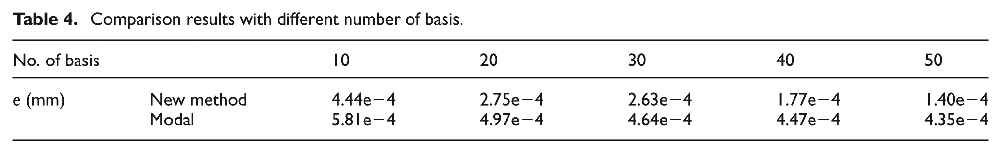
The comparison results demonstrate that the new method always outperforms modal analysis method under different number of basis. Moreover, reconstruction errors of the new method decrease much faster, which indicates that the basis used in the new method can better capture the plane form characteristics.
Statistic model of geometric form errors of multiple parts
The SMMP is established using the method proposed in section “Statistic model for geometric form errors of multiple parts,” shown in Figure 6.
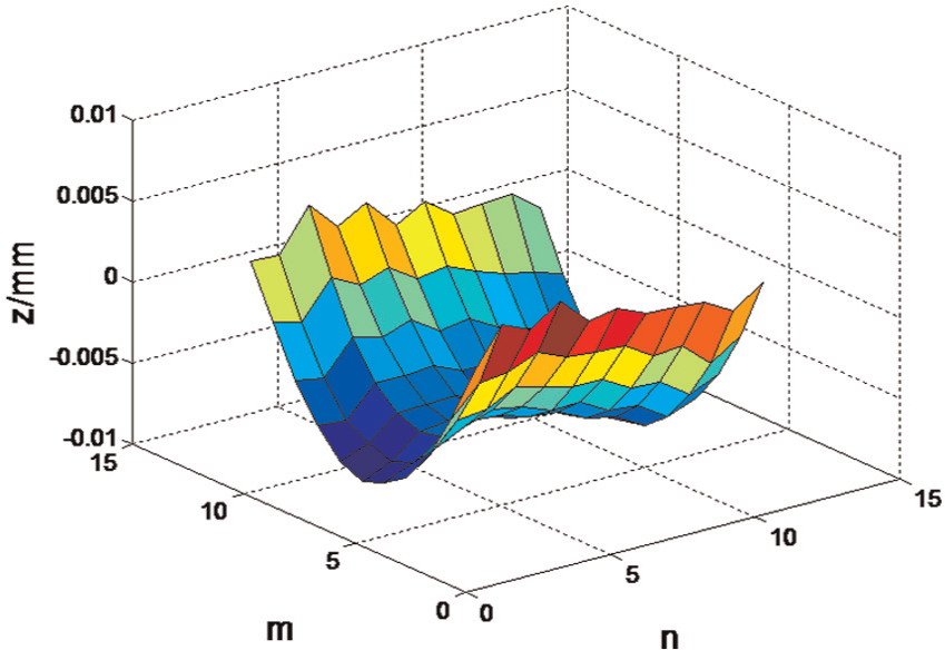
Statistic model of geometric form errors of 10 measured planes.
The characterization errors and characterization errors’ ratio of SMMP are shown in Table 5.
Characterization errors and characterization error ratios of SMMP.
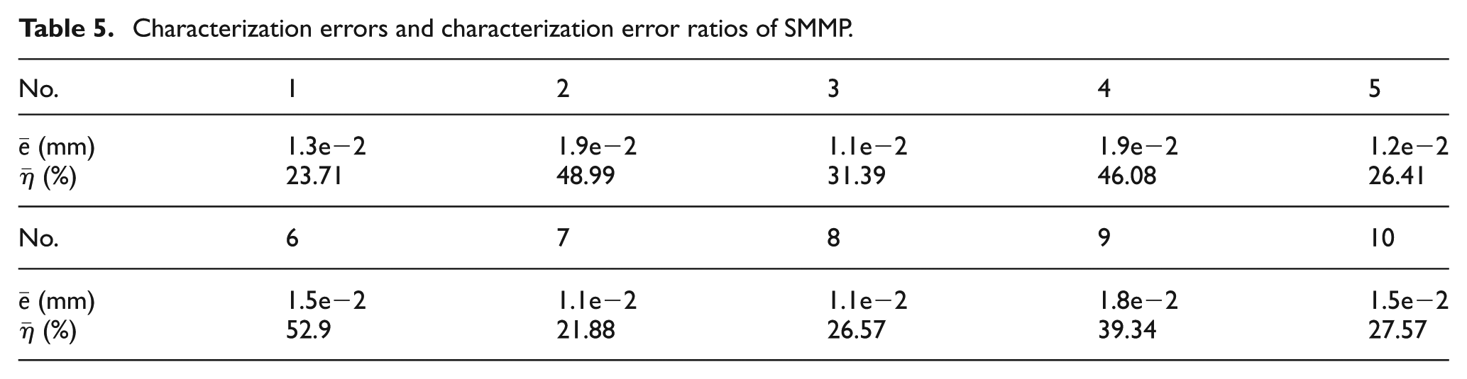
Table 5 shows that the characterization errors between SMMP and plane 2, plane 4 and plane 6 are all larger than 40%, which are quite high. The reason is mainly that the differences of the geometric form errors between the three planes and other seven planes are greatly large, and SMMP is the plane that can represent the common features of all the measured planes as well as possible, thus the characterization errors’ ratio will be relatively large for the plane quite different from other planes in the same sample. To solve the above problem and improve model accuracy, sample size should be enlarged, and then, the planes quite different from other planes in the sample are removed from the sample. Planes having much in common with each other are selected to establish SMMP.
Conclusion
Influenced by machine vibration and cutting-tool wear, the parts are always imperfect. A batch of parts machined by the same process commonly has similar form errors. It will be helpful to improve machining and assembly accuracy and product quality, if the law of geometric form errors of parts machined by the same process can be specified. However, there are no models available to describe the law.
This article develops a technique to statistically model geometric form errors. PCA method is applied to extract the common features of parts machined in the same batch, and t planes, which have more contributions to the statistic model, are selected to establish SMMP, based on the magnitudes of eigenvalues. For single parts, kernel function of DCT is taken as basis functions to model geometric form errors by linearly combining basis functions. The validity of two modeling methods is verified by two case studies. Moreover, it is demonstrated that the modeling method for single parts outperforms other methods by presenting comparative studies.
The major contribution and novelty of this article is to provide a statistic model for characterizing geometric form error distribution effectively. It has great potential to be applied to error source analysis of precision parts’ machining, assembly process optimization of precision mechanical system and assembly accuracy improvement.
It should be pointed out that further research on the modeling techniques is needed. This article is focused on only plane reconstruction, and reconstruction of more complex shapes, such as cylinders and cones, will be the future research direction.
Footnotes
Declaration of conflicting interests
The authors declare that there is no conflict of interest.
Funding
This work was supported by National Natural Science Foundation of China (grant number 51375154) and National Natural Science Foundation of China (grant number 51127004).