
Abstract
The system-level structure model significantly affects the subsequent development process. However, such a model cannot be used directly due to its document-based representation. A significant gap exists between the system-level model and the detailed domain-specific model. The model integration method significantly facilitates the design scenario involving different design phases because it supports tasks such as complexity management and consistency maintenance. However, the automated generation of the computer-aided design model from the systems modeling language-based structure model of the mechanical system is a typical issue. In this study, a meta-model-based approach is proposed to generate the initial computer-aided design model represented by the STEP file from the systems modeling language-based system structure model. A geometry-related system structure modeling method is described, and the triple graph grammar is introduced to transform the systems modeling language model into the EXPRESS model. An automated generation algorithm is proposed to construct the initial computer-aided design model for mechanical systems against the ISO 10303-203 (AP 203) standard by parsing the EXPRESS model. Our approach facilitates model integration and helps reduce the gap between the system-level structure model and the computer-aided design model. This reduction would be beneficial for eliminating misunderstandings between different designers and thus to accelerate the design process. Finally, an example of an engine is provided to illustrate the proposed method.
Keywords
Introduction
Conceptual design is important to product design.1,2 SysML is a systems modeling language used in systems engineering 3 to support conceptual design. It has been widely studied for modeling the system structure of the mechanical subsystem of complex mechatronic systems4–6 and for system-level analysis and simulation.7,8 How to use the system structure information to accelerate the development of the subsequent detailed design remains unsolved. Recently, some researches have studied the integration of the system structure model with the detailed design model.9–11 However, to our knowledge, there are several common deficiencies in this research. The first deficiency is the lack of a modeling method to describe the geometric information of the system structure. Many researchers have recognized the importance of rough geometric information for conceptual design as product complexity increases.12–15 Some researchers have even introduced embodiment design into conceptual design. 16 Assisted by rough geometric information, the concept variants can be evaluated more thoroughly and precisely. 12 However, most of existing researches only specified the design parameters and the organization hierarchy for the system structure. The second deficiency is the automated generation of the initial computer-aided design (CAD) model from the SysML-based system structure model. Currently, the initial CAD model is created manually according to the designer’s understanding of the system structure model. This manual process is prone to misunderstandings due to different interpretations. 17 In fact, despite representing geometric shape only approximately, the geometry-based initial CAD model may be one of the best communication means between the system modeler and the CAD modeler for designing the mechanical system. 18
Based on the above analysis, a SysML-based modeling method is proposed to formally describe the geometric information of the system structure model. The initial CAD model will be automatically generated from the SysML-based model and will then serve to launch the later phase. The STEP file 19 is chosen to describe the target CAD model for high generality. As the STEP file is specified by the EXPRESS entities, 20 the SysML model can be transformed into the EXPRESS model using a model transformation method such as the triple graph grammar (TGG) method. 21 Then, the EXPRESS model is parsed to generate the final STEP file because the output format of model transformation is XML-based Metadata Interchange (XMI). Similar technology was applied for connecting the existing system models and CAD models (not generating the models from scratch) in Hamid. 9
The article is organized as follows. Related work is discussed in section “Related work.” In section “Method overview,” an overview of the proposed method is given. How to extend SysML to model the geometric information for the system structure is discussed in section “Geometry-related mechanical system modeling in SysML.” The transformation method, including the meta-model definition and the TGG specification, is described in section “TGG-based model transformation.” The method for generating the initial CAD model is presented in section “Detailed model generation.” Using a case study, the implementation of the proposed method is described in section “Implementation and case study.” The proposed method is discussed in section “Discussion.” Finally, the conclusion and possibilities for future work are presented in section “Conclusion and future work.”
Related work
Geometric information in conceptual design phase
Geometric information has been typically overlooked in the conceptual design phase. 12 However, representing geometric information in the conceptual design is gaining increasing attention as product complexity increases. Horvath 13 noted that geometric information was crucial to conceptual design. Based on the emphasis on the importance of an approximate physical form in the conceptual design phase, Roy et al. 14 proposed the introduction of the location and orientation to the artifact definition. Certain spatial constraints were also employed. Komoto and Tomiyama 12 constructed a class hierarchy of spatial relations to describe the preliminary layout information for the conceptual design and thus to evaluate the occurrence of physical phenomena. Recently, Helms 15 highlighted the importance of geometric relations between the components of the conceptual design.
Geometric information representation in SysML
Given the wide use of SysML for systems modeling, how to model the geometric information of the system structure in SysML has become a relevant question. 4 Many studies5,9,11 have represented physical structure information in SysML. However, a common drawback in these studies is that only design parameters are explicitly modeled. The physical components arrangement hence remains unspecified. Therefore, Martin et al. 4 suggested that the rough geometric constraints between mechanical components should be specified in SysML. This specification is critical for unambiguously representing the relationship between the physical components during the conceptual design phase.
SysML-based model integration
Integrating the SysML model with multidisciplinary models is important for supporting mechatronic design. 5 Because of the wide use of SysML, much research has been conducted on the SysML-based model transformation and integration. Chami et al. 22 used the SysML model to integrate multi-domain models together to address the complexity of different design stages for multi-domain models. Kim et al. 23 integrated the SysML models with analysis models, thereby enabling designers to quickly evaluate system configurations by executing the analysis models. Branscomb et al. 24 developed a vehicle architecture modeling framework (VAMF), which combined SysML, Modelica and Simulink models in a systematic process to generate a fully integrated vehicle-level attribute analysis model. Similar studies have been conducted by other researchers.25–27 In addition, the authors performed similar work on the model transformation between the SysML-based system design model and the Simscape-based simulation model based on TGG.7,8
Summary
The above analysis indicates that many studies attempt to use SysML-based model integration to generate different types of models, for example, the analysis model,23–25 the simulation model7,26,27 and the control model, 8 from the SysML models. However, the integration of SysML models with CAD models has received little attention. 5 Specifically, the geometry-related modeling method is missing in these approaches using SysML. Martin et al. 4 considered that the usefulness of SysML is the most critical for the mechanical subsystem. In summary, the existing methods do not support the generation of initial CAD model from the SysML model. 5
Method overview
In this study, a SysML-based method is proposed to automatically generate the initial CAD model from the system structure of mechanical system. For the target CAD model, a logical choice is to select a specific platform such as Solid-Edge. 9 However, to decouple the CAD model from the specific CAD platforms, a neutral modeling language, EXPRESS, is adopted here. Therefore, the EXPRESS-based file for the Exchange of Product model data (STEP) is introduced because it is supported by all mainstream commercial CAD platforms. It is also easy to extend the proposed approach to generate a platform-specific CAD model, as mentioned in the discussion section.
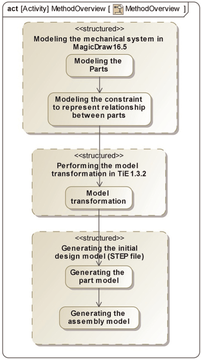
The main steps of the proposed method are provided in Figure 1. Assisted by the powerful extension capability of SysML, the first step is to represent the geometric information of the system structure in SysML. Typically, the complex system structure is comprised of multiple connected components. 28 Therefore, the main elements in the system structure model are the components and the relationships between them that collectively constitute a group. Correspondingly, there are two types of mechanical information considered in systems modeling, namely, the system parts and the spatial constraints of parts. The former includes the representation of the geometric information of the parts and their semantic attributes, and the latter describes the spatial relationships between the parts.
Method overview.
The second step involves the model transformation from the SysML model to the EXPRESS model. Here, the TGG-based method is used. To facilitate the creation of the initial CAD model, it is necessary to establish an association between the elements of the system models and those of the CAD models. Two methods can be used: (1) extracting information from the SysML model directly or (2) constructing the intermediate model to bridge the elements. The former method is inefficient because the initial SysML-based system model is complex, and it is nontrivial to extract the necessary information. The latter method is preferred in terms of the following aspects. First, the required information can be reorganized to compose new models, thus minimizing the amount of information to be processed. Second, a general model transformation method such as TGG can be used to guarantee model consistency. 29 Unnecessary information can be conveniently filtered using the TGG method, which in turn facilitates the former aspect, the minimization of information. Finally, the EXPRESS-based model can be used as the intermediate model because EXPRESS is not only the data specification language of the STEP file but also a part of the STEP standard set. Therefore, the EXPRESS-based model is constructed to transmit the necessary information from the SysML model to the CAD model. Note that the meta-models of SysML and EXPRESS should be defined to perform the model transformation.
The third step requires parsing the EXPRESS model to obtain the initial information of the mechanical parts and the constraints between them. Based on the shape parameters and the constraint information contained in the EXPRESS-based model, the final STEP file for the mechanical system is generated.
Geometry-related mechanical system modeling in SysML
In SysML, the block definition diagram (BDD), the internal block diagram (IBD) and the parametric diagram (PAR) are frequently used to describe the system model. For each BDD of a given component, certain attributes and constraints are defined to describe the model’s properties. However, general-purpose modeling elements are unsuitable for specific domains 4 because they cannot support the representation of domain-specific semantics. To facilitate the representation of geometric information, the SysML extension mechanism is used. There are two extension mechanisms for SysML: the heavyweight method and the lightweight method. The former extends SysML by defining new meta-classes. It is the first-class extensibility handled through Meta Object Facility (MOF) 30 that imposes no restrictions on how the meta-model can be used. However, the disadvantage of the heavyweight extension is that the Unified Modeling Language (UML) tools should also be updated when new meta-classes are defined. The lightweight method extends SysML by creating stereotypes based on the existing constructs. Therefore, it can be implemented using the existing UML tools.31,32 Based on the above analysis, the lightweight extension is chosen here. 33
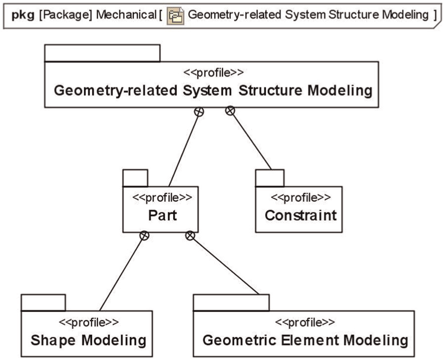
In this study, the proposed geometry-related modeling profile for representing the system structure includes two subprofiles: a part profile and a constraint profile. The former profile depicts how to define the stereotypes to associate specific geometry-related engineering semantics with the system part models, whereas the latter specifies how to describe the spatial relationships between parts. Each part has a distinct geometric shape for visually representing its specific purpose. To characterize each part’s interaction with other parts, the concept interface feature is defined. Additionally, a constraint profile is defined to represent the spatial relationships between parts. Based on the above analysis, the system structure modeling profile is shown in Figure 2.
Mechanical systems modeling profile.
As shown in Figure 2, the part profile contains two indispensable subprofiles: the shape modeling profile and the geometric element modeling profile. The former defines the basic shapes, and the latter introduces the basic geometric elements prepared for constraint modeling. Together, these profiles enable part modeling.
Part profile
Shape modeling subprofile
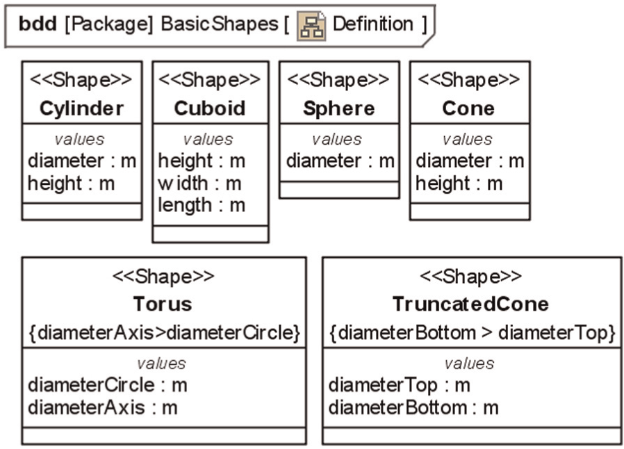
At the beginning of the design process, every mechanical part has an approximate shape that will be refined later. Here, the «Shape» stereotype is extended from the Block of SysML to represent the different elementary shapes. In this study, six typical shape types are defined, as shown in Figure 3: cylinder, cuboid, sphere, cone, torus and truncated cone. These shapes form the library of basic elements for representing the initial shape of the mechanical part in the system model. The essential parameters are defined as the properties for each type of shape. Note that the properties are highly important because they will serve as the primary modeling parameters of each part. Certain constraints are also defined for these rough shape types. For example, the constraint definition for the torus requires that the diameter of the rotation axis be sufficiently large to prevent the axis of revolution from touching the circle.
Six types of typical basic shapes.
Geometric element modeling subprofile
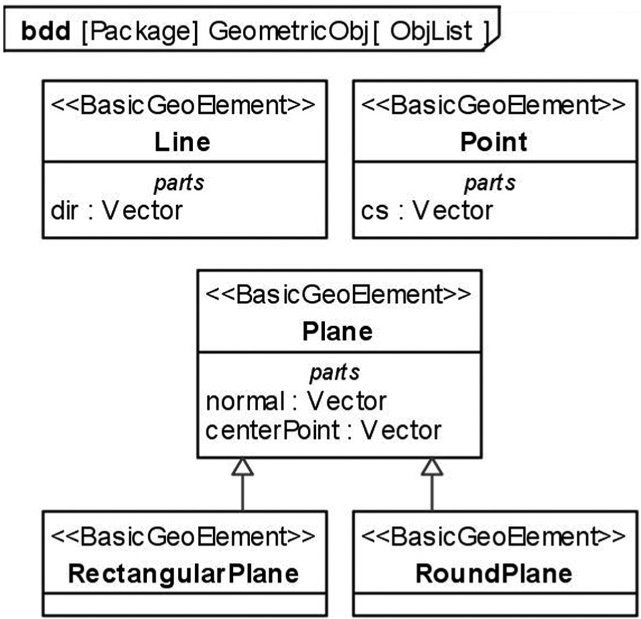
As proposed by Chen and colleagues,34,35 the basic geometric elements of most CAD systems on which the common geometric constraints imposed include point, line and plane. They should be defined, upon which definitions the constraints can be modeled. Here, they are specified by the stereotype «BasicGeoElement», as shown in Figure 4. The vector-typed attribute defined in Point represents the coordinates, while the attributes defined in Line indicate the direction information. The Plane contains the normal vector, which is inherited by two subtypes, RectangularPlane and RoundPlane. To construct the constraint definition, certain regular points must be indicated with respect to the plane types. The definition of the center of the plane type is provided, and certain specific constraints (e.g. Fixed constraint in Chen and colleagues34,35) can act on the plane.
Basic interface features.
Part modeling
The part semantics is essentially characterized by the shape and the interface feature properties. Usually, a part has a tangible body characterized by a certain shape type. A part, in turn, has certain specific points, lines or planes on which the constraints could be imposed to constitute the system. Here, the point, line and plane are basic geometric elements that act as the interface features of the part. Consequently, «Body» and «InterfaceFeature» stereotypes extending from the «Property» are defined. Their application is clear from the Block part definition, as shown in Figure 5. As the part interacts with each other based on the interface features, the «InterfaceFeaturePort» stereotype is proposed to enable each part to expose interface features to the outside. As shown in Figure 5, six interface feature ports are defined for the part, and each port is exposed to a specific face to facilitate the composition of the system. Consequently, the constraints can be defined on any face of a block. For each shape type, certain basic geometric elements are specified as the interface features for the constraint definition.
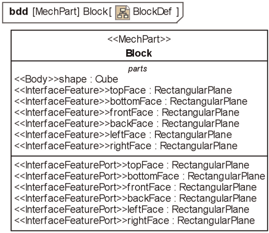
Block part definition.
Constraint profile
As previously mentioned, the parts must be constrained together to generate the subsystems and eventually the entire system through their interface features. The spatial relationships between parts are represented by different constraint types. The common geometric constraint types proposed in Chen and colleagues34,35 can be classified into two types: position constraints and direction constraints. Therefore, the «PositionConstraint» and «DirectionConstraint» stereotypes extending from the ConstraintBlock of SysML are defined to represent these types. The constraint types are explicitly modeled for all possible element types. Note that some constraint types can be implemented directly or indirectly.
To explain the modeling principle, certain constraint-type definitions are specified, as shown in Figure 6. For example, the parallelism constraint can apply to a line and a plane, and the LineParallelism and PlaneParallelism constraints are thus provided simultaneously. Some constraints, however, can restrict the position and direction and should be characterized by both stereotypes, for example, the PlaneFixed type. Moreover, some constraint types require additional values to restrict the position or the direction absolutely, as demonstrated by the PlaneFixed and PlaneDirection constraints.
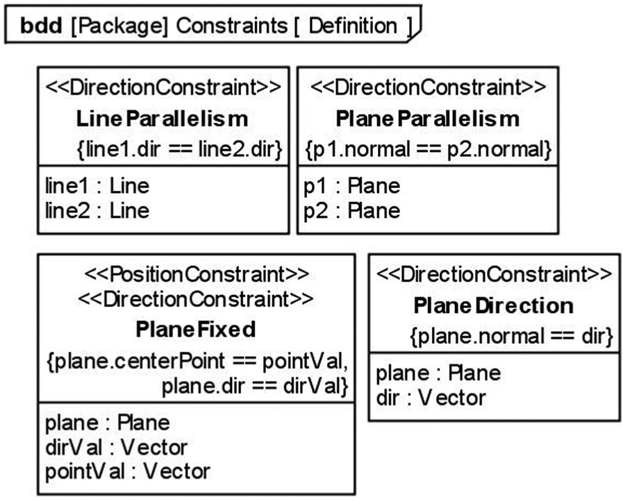
Constraint-type definitions (partial).
TGG-based model transformation
To generate the CAD model, the meta-model-based transformation method is adopted. The basic transformation framework 36 can be represented by Figure 7. Figure 7 shows that the central problems are the definition of the meta-models of the source model and the target model, and the transformation rules between the models. Subsequently, the source model can be transformed into the target model based on the transformation definition. Among all model transformation methods, the TGG-based method is chosen based on the comparison results in Königs. 21
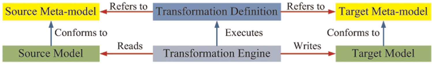
Basic model transformation framework.
Meta-model definitions
Meta-model of the source model
The meta-model mechanism definition of the source model can generally be divided into two parts: the first part involves the stereotypes extended from the basic types of SysML, while the second part involves the definition of the relationships between the customized stereotypes discussed in section “Geometry-related mechanical system modeling in SysML.” The meta-model of the mechanical systems modeling is defined, as shown in Figure 8. For simplicity, the extension relationships between the stereotypes and the meta-models of SysML are not displayed because they are described in the previous section.
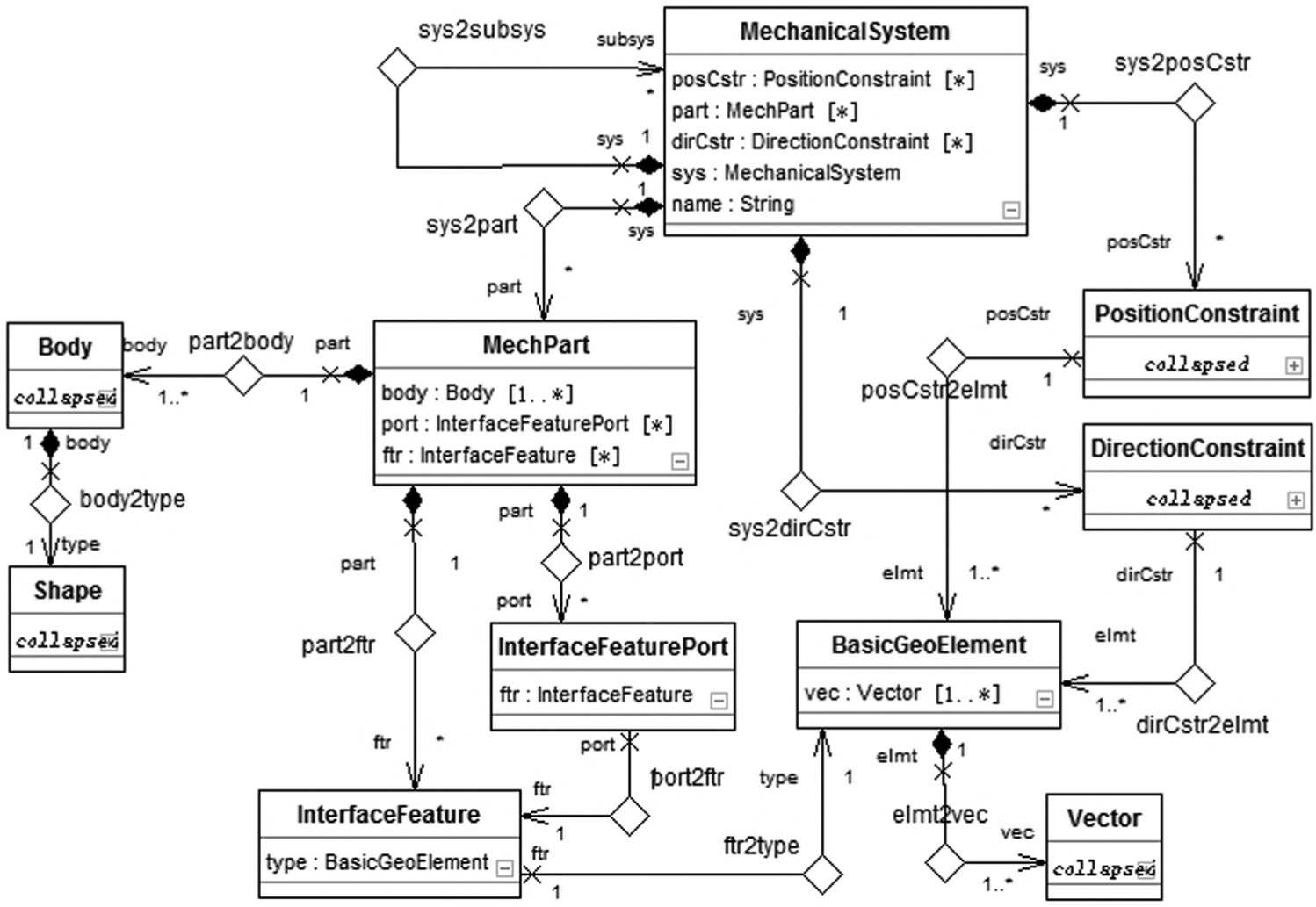
Meta-model of the source model. : Generalization relationship describing the inheritance between two classes that starts from the subclass and points to the superclass. : Association relation describing the properties or relations between two elements, one of which is navigable. : Composition relationship describing the part-of-a-whole relationship between two ends.
Meta-model of the target model
Based on Barbau et al., 37 the relevant subset of the EXPRESS meta-model is given, as shown in Figure 9. The main concepts are Entity and Attribute. The latter is characterized by the abstract-type ParameterType (italicized to denote that it is an abstract type). Both SimpleType and Entity are also its subtypes. The Entity instance can be further constrained by two types of local rules: uniqueness rules and domain rules. The former controls the uniqueness of attribute values among all instances derived from a specific entity type, while the latter describes other constraints on the attribute values for each instance. 20
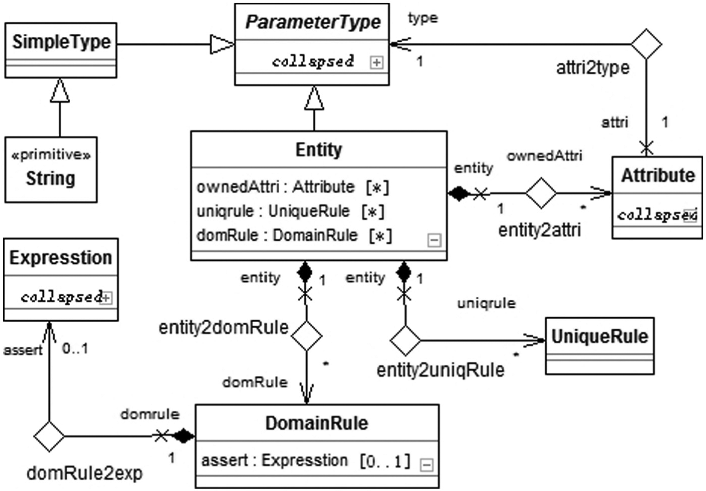
Meta-model of the target model.
TGG specification between meta-models
Several methods have been introduced for model transformation to support model-based engineering.36,38–40 Here, the TGG-based method presented in Königs 21 is used because of specific advantages, such as graphical notation, Java Metadata Interface (JMI) compliant code generation and bidirectional transformation. A detailed introduction of the TGG-based model transformation is available in Cao et al.7,8
The TGG method implements the model transformation by specifying (1) which target model is mapped to the source model and (2) how to derive the target model from the source model. Correspondingly, the TGG link type and the TGG rule are specified to perform these tasks.
TGG link type
To satisfy the transformation definition, the correspondence between the source and target models should first be declared. The meta-model mappings between the language EXPRESS and UML can be extracted according to the ISO 10303 Part 25. 41 In this case, a subset of the meta-models is required, as shown in Table 1. Based on this subset, the link types can be specified for the mapping relations. Figure 10 shows the link type Sys2Entity between the Class (named Clazz to avoid conflicts with JMI-compliant code generation) and Entity from two domains. Assisted by the TGG link type, the corresponding relationships between the source and target meta-models can be defined.
A subset of meta-model mappings.
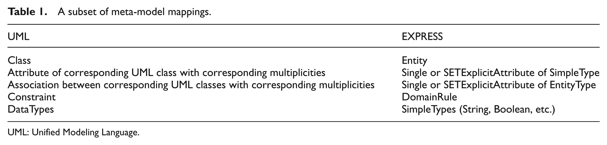
UML: Unified Modeling Language.
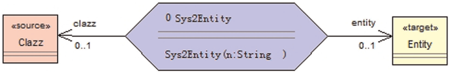
TGG link type.
TGG rule
Because the TGG link types indicate only the correspondences between meta-model elements, TGG rules must be added with various conditions to describe how the target model is to be built from the source model, namely, under what conditions the transformation can be executed. The TGG rule can be abstracted and formalized into a quaternion (OT, PT, BC, CC).7,42
OT is the objective transformation that contains three objects instantiated from the classes in the integration link type definition. The objects from the source meta-model and target meta-model can be called transformable objects. After one transformable object is created, the other transformational objects should be added simultaneously. In each rule, there is only one OT.
PT represents the transformation between properties of the transformable objects. The properties of the elements include simple properties of the primitive/simple type and referring properties of other classes in the meta-model. The transformation of simple properties is implemented by sharing the same rule parameters between corresponding properties of the source and target elements. Before creating referring properties, the type classes of the properties and the correspondence of the type classes should exist. By creating links between the property types and the transformable objects, the property transformation is defined.
BC represents the belonging condition indicating the existence of the objects that contain transformable objects as their sub-elements. Before the transformation, the belonging objects and their correspondence should exist. Afterward, the new created transformable objects are attached to the belonging objects.
CC is the constraining condition that transformable objects must satisfy before the transformation can be conducted. There are two types of conditions. The attribute condition constrains the values of the properties of the elements on which the rule works. The referring condition indicates that a certain element has referred the transformable objects as its property.
Each rule can have zero or several BCs, CCs, and PTs. Different TGG rules can be defined by adding different BCs, CCs or PTs to the OT.
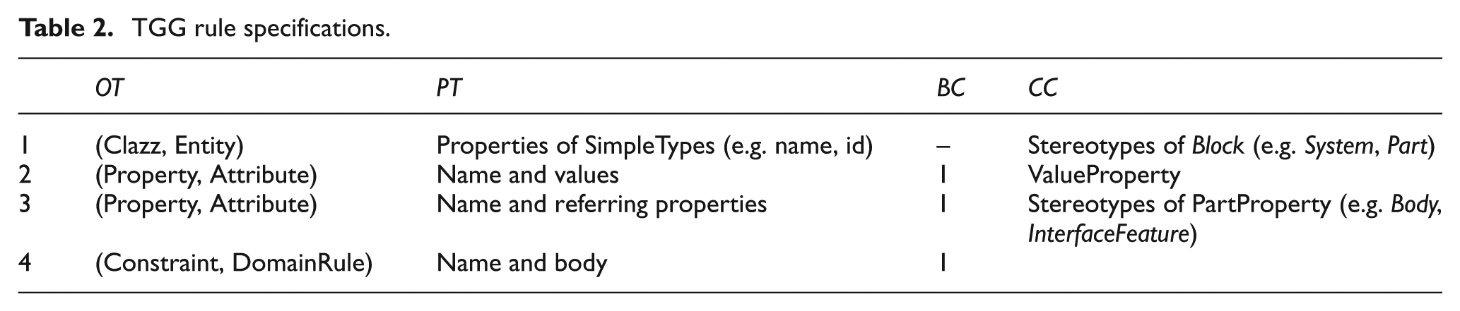
Figure 11 shows a TGG rule example applied to the Property and the Attribute elements srcObj2 and trgObj2 (OT at second level). The PT includes the assignment of the ID and the linkage between Property and Class as well as between Attribute and Entity (at the second and third levels). The BC shown at the first level indicates that the Class object and the Entity object should exist before the transformation, while both newly created objects should be attached to these objects after the transformation. The CC shown on the fourth level indicates that the Property object should be stereotyped by the PartProperty stereotype; otherwise, the transformation will not occur. The detailed TGG rule specifications for the mappings in Table 1 are listed in Table 2.
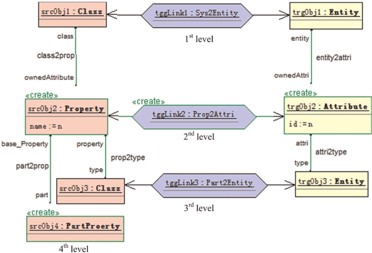
TGG rule definition.
TGG rule specifications.
Integration framework
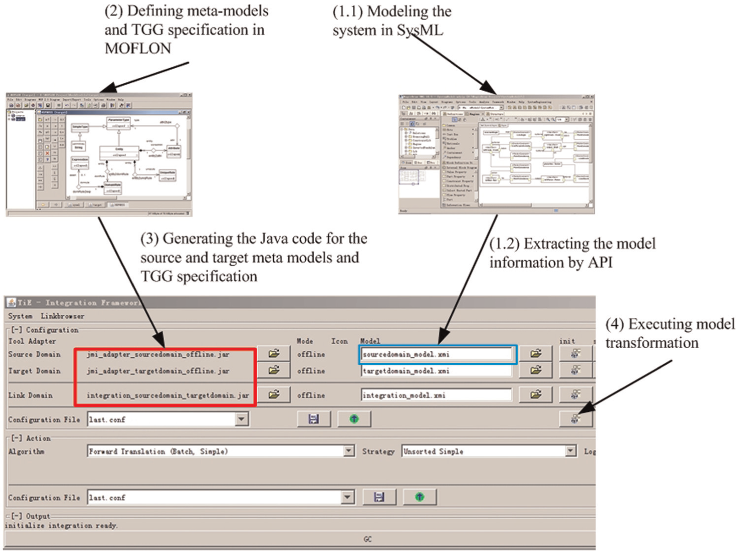
After the TGG link types are specified for the meta-models of both domains, the JMI-compliant code can be generated automatically with the MOFLON tool, 43 which includes a MOF 2.0 44 diagram editor for meta-modeling. The TGG method is also implemented as a plug-in of this tool and thus facilitates the entire task of model transformation. Then, the integration framework of tool integration environment (TiE) 45 is constructed, and the transformation definition is applied to perform model transformation tasks. The input source model file can thus be transformed into the target model automatically. The entire process includes four main steps, as shown in Figure 12:
Model the system structure in SysML and generate the model (i.e. the output) as an XMI file.
Model the meta-models in MOFLON with the MOF 2.0 editor. Determine the TGG specification for the corresponding meta-models with the TGG plug-in of the MOFLON tool.
Generate the JMI-compliant code for the source meta-model, the target meta-model and the TGG specification.
Perform the model transformation based on the TiE integration framework.
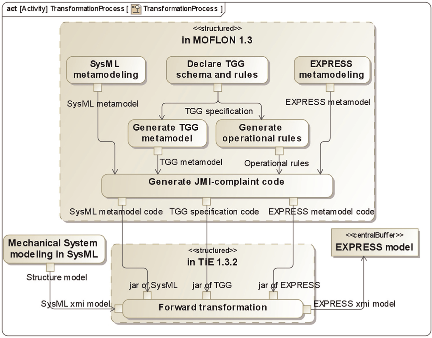
Entire transformation process.
The input for the transformation hence includes the systems modeling file (XMI format), the Java code for the meta-model specifications and the TGG specification, and the output is the target EXPRESS model (in XMI format). Note that the transformation process is executed automatically by the TiE tool after the source model is inputted.
Detailed model generation
A compatible model for CAD systems must nevertheless be generated because the transformed EXPRESS model in XMI format cannot be directly used by commercial CAD systems. However, the neutral STEP file 46 is compatible with various CAD systems and is thus selected to represent the CAD model.
Typically, the mechanical system is represented by an assembly model, which is comprised of a group of constrained parts. Therefore, the part information and the constraint information must be extracted from the EXPRESS-based model to generate the initial CAD model. The entire process for parsing the EXPRESS-based model is outlined in Figure 13. The process entails two crucial tasks: part model generation and transformation data calculation. The first task is completed with a part model generator (PMG) based on a template-based method. The matching information (MI) is updated after the geometric model is prepared. The second task entails deriving the transformation data based on the transformation matrix. This matrix can be computed when both local coordinates in part environment and the global coordinates in assembly are provided for the MI.
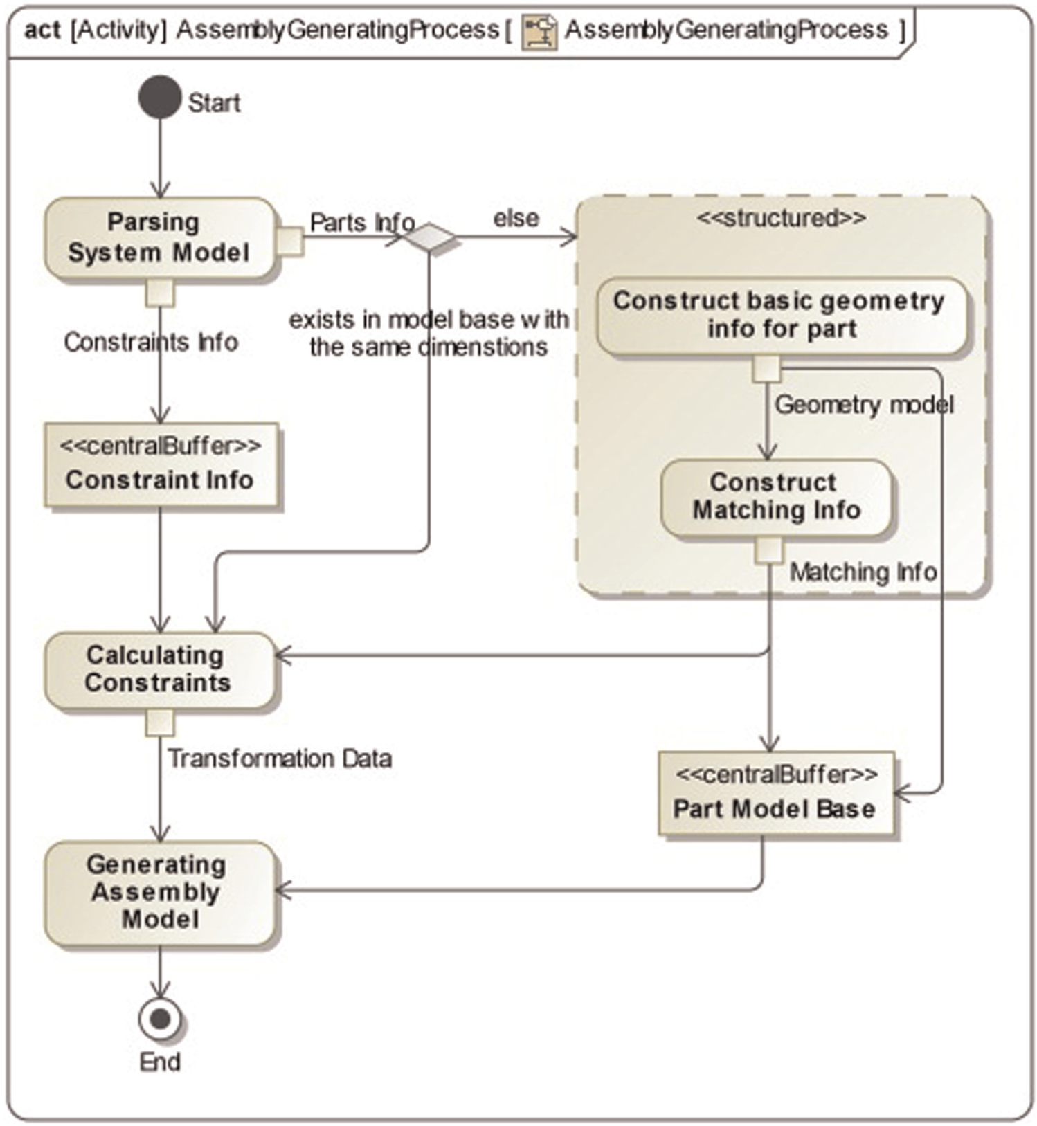
Assembly model generation process.
Part model generation
As mentioned, the PMG performs the model generation of the parts in two steps based on templates. One step involves the reconstruction of a basic geometric model, and the other step initializes the MI. The former step generates the B_Rep model with correct dimensions for the part, while the latter step constructs the MI of the part.
Basic geometric model reconstruction
The basic geometric model of the mechanical part includes both the topological and geometrical information. The model is a B_Rep model based on the AP 203 standard used here. The geometric model of a specific part type determines the topological information; the part instances instantiated with different dimensions only differ in geometrical information; that is, such instances share common topological information. Figure 14 shows both types of information for the AP 203-based B_Rep model of a block part with dimensional parameters 5 mm × 4 mm × 3 mm. In other words, for another block part instantiated with dimensions 10 mm × 8 mm × 6 mm, the B_Rep model is derived by setting the parameters equal to the new values (i.e. replacing 5, 4 and 3 with 10, 8 and 6, respectively, in Figure 14). Interested readers may refer to ISO 10303-203:1994 19 and AP 203 47 for a more detailed description of the AP 203-based B_Rep structure.
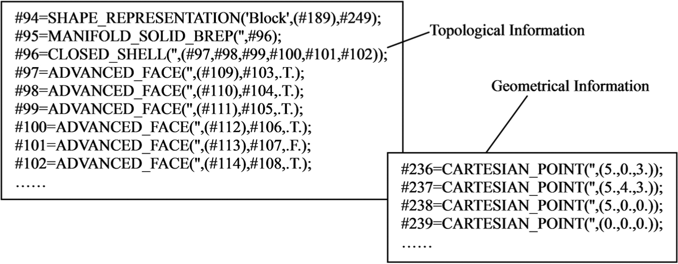
Topological and geometrical information (partial).
Based on the above analysis, a template-based method is proposed, and a template is predefined for every basic shape type noted in section “Geometry-related mechanical system modeling in SysML.” Using templates, a new part can be obtained by updating the parameters of the related items. Each item of geometrical information is determined only by the parameters, and the relationship between a single geometrical information item and the parameters is maintained by the rules. A template database is employed to store the templates of the basic shape types to facilitate the PMG execution. The PMG structure is shown in Figure 15.
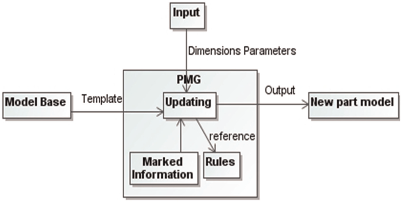
PMG structure.
MI construction
The MI includes the coordinates of geometric elements (in the local part environment) to provide the input for the transformation data calculation that is performed at a later stage. For an interface feature, only the information explicitly modeled in Figure 4 must be marked. The MI of basic shape types is defined, as shown in Table 3. As evident from the table, the MI is prepared for some standard points, lines and planes. For example, the points are defined as the centers of both ends of a cylinder.
Standard interface features and the MI of basic shape types.
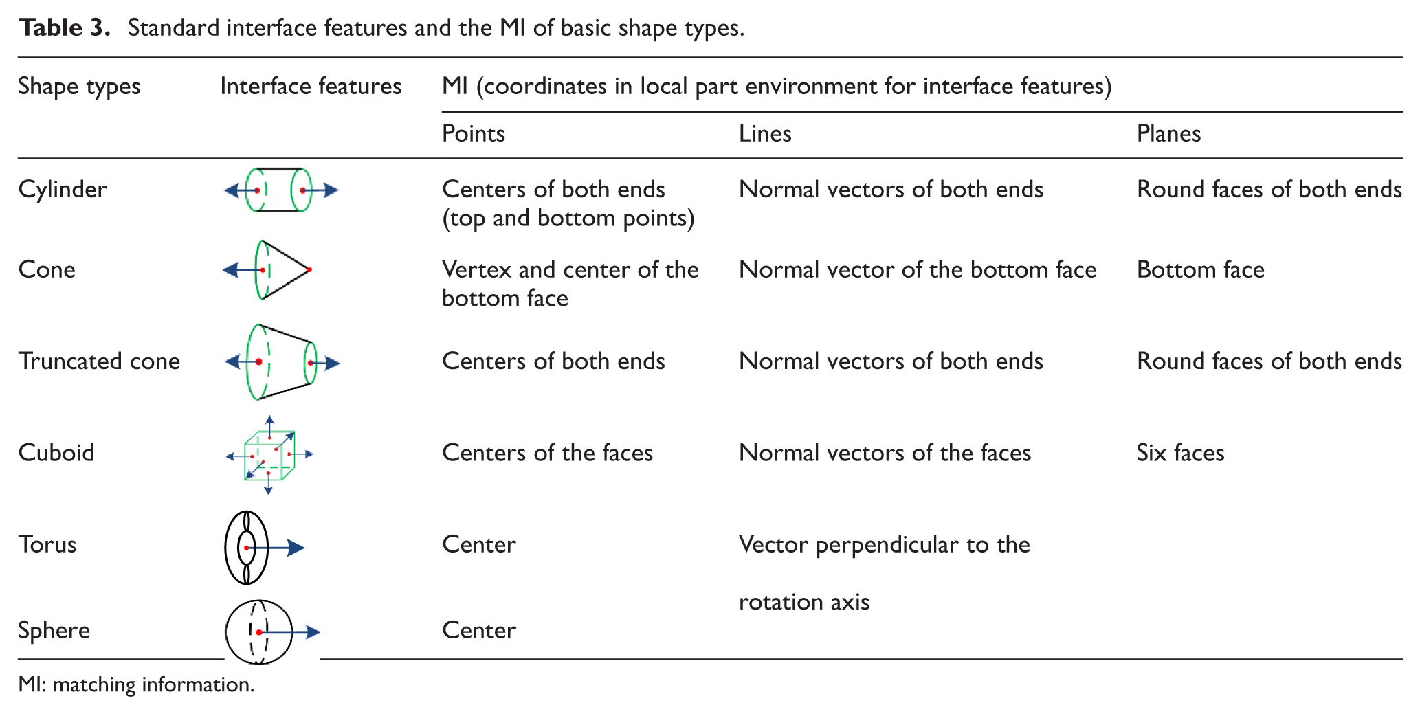
MI: matching information.
Assembly model generation
After the part models are generated, the assembly model is generated by calculating the transformation data based on the spatial relationships first and then by assembling the parts together using the transformation data.
The introduction of transformation data
The transformation data specify both the location and the orientation for a part instance in the assembly environment. According to ISO 10303-203:1994, 19 such data can be illustrated by Figure 16. Figure 16(a) shows the global coordinate system (with subscript g) for the assembly, and Figure 16(b) is the local coordinate system (with subscript l) for a part. If the cylinder-shaped part is assembled as shown in Figure 16(c), it is clear that
The positive direction of the axis xl equals that of yg , that is, (0, 1, 0), in the assembly environment.
The positive direction of the axis zl equals that of xg , that is, (1, 0, 0), in the assembly environment.
The coordinate value of the origin point of the part is (1, 1, 1) in the assembly environment.
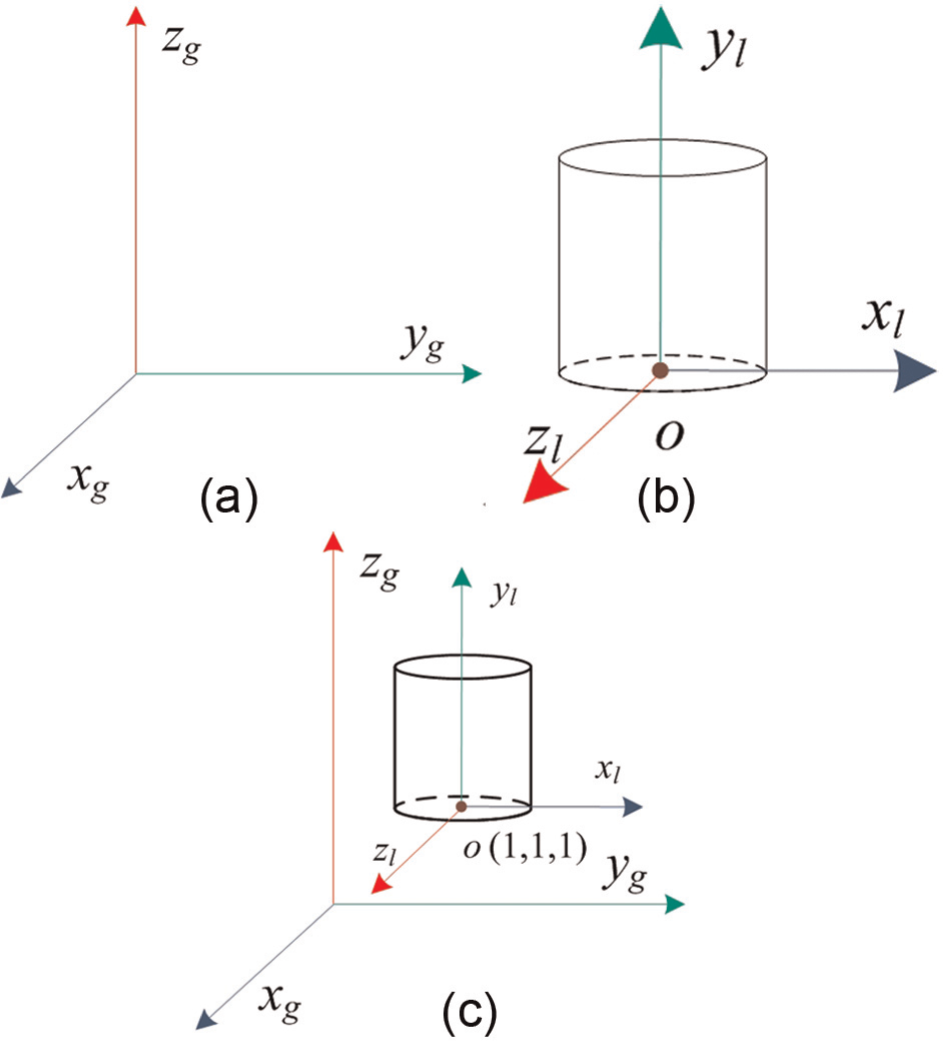
Assembling a part into the assembly: (a) global coordinate system, (b) local coordinate system and (c) assembling result.
Therefore, the transformation data of the part are
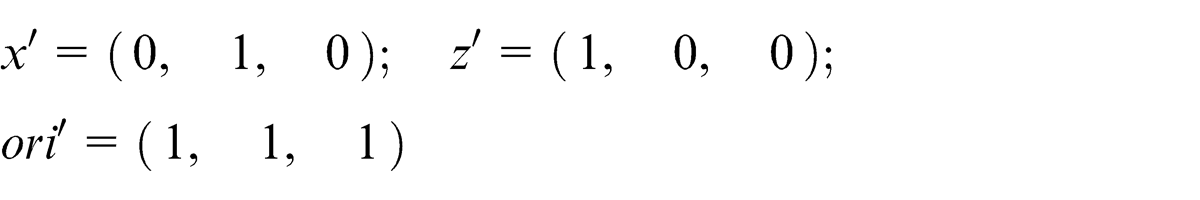
Calculation of transformation data
After the part models are obtained, the chief problem is determining the part transformation data in the assembly environment, specifically (1) the position of the part origin, (2) the direction of the X-axis and (3) the direction of the Z-axis. However, to obtain the transformation data, the transformation matrix should be determined first, which requires two additional conditions: (1) the MI of the part environment and (2) the MI of the assembly environment. The former is known after the part model is prepared, while the latter is determined for every part using the spatial constraints between the interface features.
A constraint-based algorithm is proposed to calculate the transformation data. Based on the known parts and the initialized MI, the coordinates are calculated in the assembly environment for the adjacent parts based on the constraints on them, as follows. Given a mechanical system S with a group of parts p1, p2,…, pn , an arbitrary part, for example, p1, is assembled without transformation at the beginning of the process. The MI of the interface features on p1 represents the start of the calculation. Assuming p1 and p2 are connected by interface features f1 and f2, respectively, the coordinates for MI of f2 are determined by computing the constraints between them. If the MI in the assembly environment is determined for all the interface features of p2, then the transformation matrix can be calculated, and the transformation data are known. The pseudo-code for the algorithm is elaborated in Figure 17.
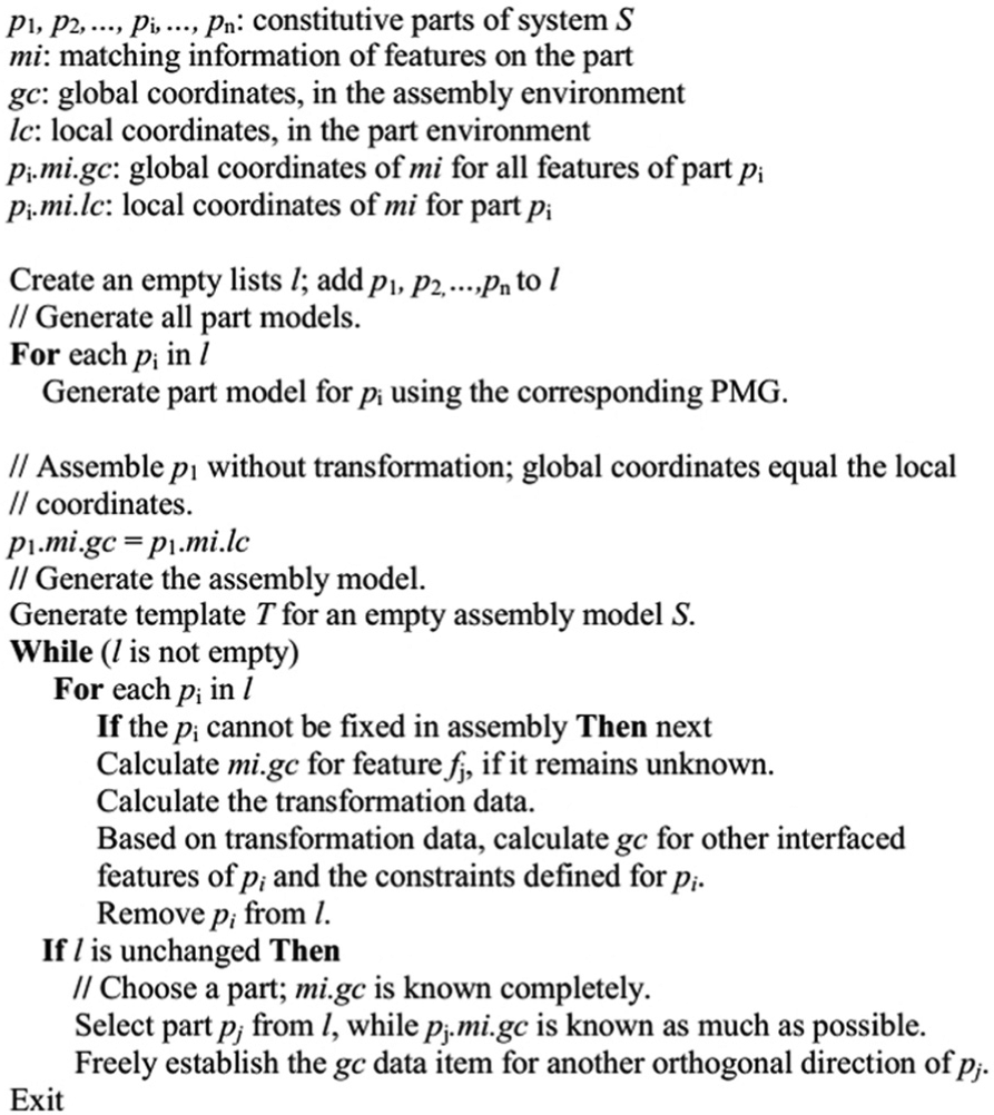
Transformation data calculation algorithm.
AP 203-based assembly model construction
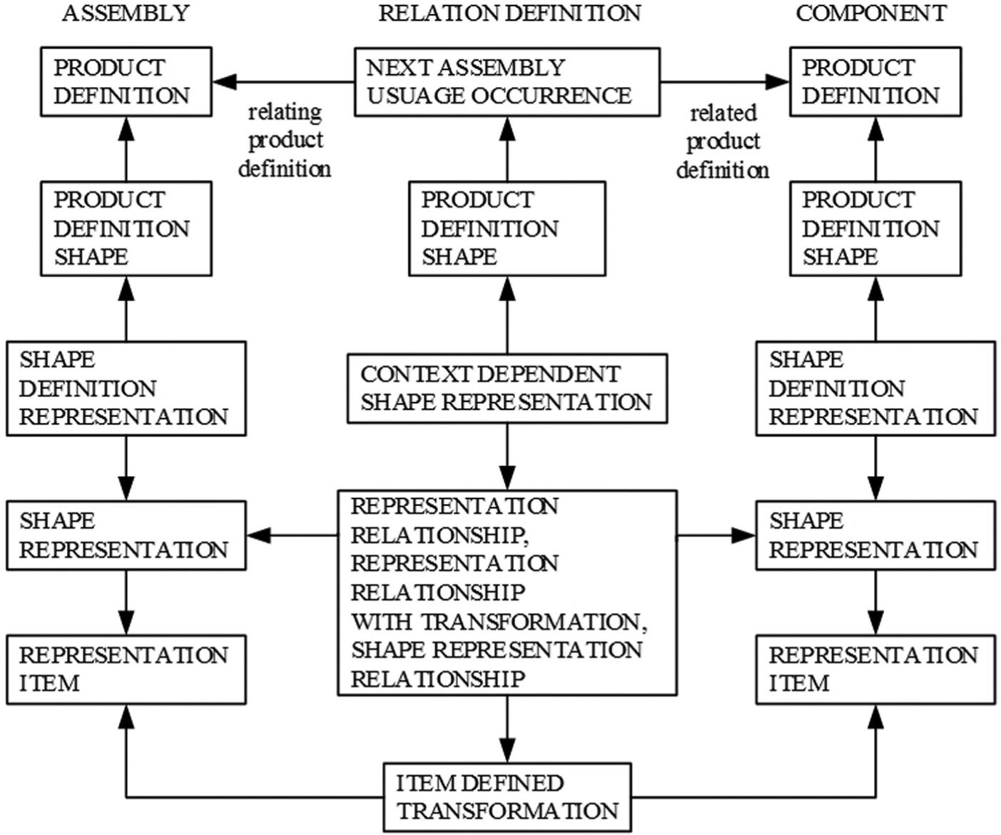
Before the construction, the structure of AP 203-based assembly model is briefly described. As stated in AP 203, 47 the core entities of the assembly model can be divided into three sub-structures (as shown in Appendix 1). In view of the limited space, all entities cannot be discussed here. Readers can refer to ISO 10303-203:1994 19 and AP 203 47 Generally, the left side of Figure 30 represents the core entity structure of the assembly, and the right represents the core entity structure of the part. The structures are similar because the assemblies are defined as the parts in the same way in AP 203. 47 The middle part specifies how to relate the shape of a part to that of its assembly. After the shape is defined for each part, the relation is accomplished by integrating the part instance into the assembly environment. This integration can be repeated each time a part instance of a certain part type requires insertion into the assembly. These sub-structures can be extracted as templates according to the discussion in AP 203. 47
Based on the analysis, a template-based method is proposed to generate the assembly model, as illustrated by Figure 18. The PMG and the transformation data calculator facilitate the B_Rep model generation and the calculation process, respectively. Consequently, the part product definition template embeds the B_Rep model to construct the part definition. Meanwhile, the relation definition template introduces the transformation data to specify each part instance in assembly. Finally, all the information is inputted into the assembly template to construct the AP 203-based assembly model.
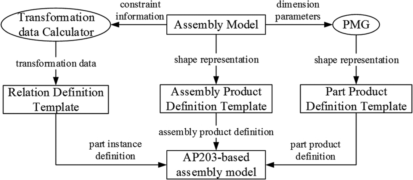
Template-based assembly model generation.
Figure 30 shows that both the sub-assembly and part are termed as components in the core structure of AP 203. Accordingly, the mapping of the core structures of SysML and AP 203 is listed in Table 4. The “system” in SysML corresponds to the “assembly” in AP 203, while both the “subsystem” and the “part” are mapped onto the “component” in AP 203. Additionally, the definition of a relation is required for a component to associate it with the assembly in AP 203. The shape information specified in SysML can be directly represented with the B_Rep model in AP 203. However, the arrangement of physical components is implicitly modeled by the position and direction constraints in SysML. Further calculations must be performed to derive the transformation data required in AP 203.
Structure mapping of SysML and STEP AP 203.
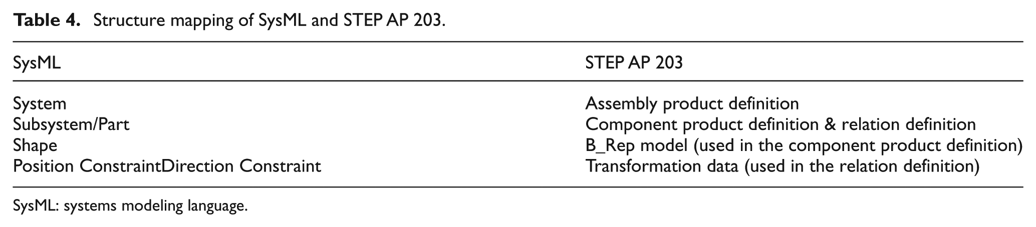
SysML: systems modeling language.
Implementation and case study
The proposed method is implemented based on MagicDraw™ 16.5. 48 As shown in Figure 19, a professional designer is invited to model an industrial engine to demonstrate the proposed method. The task is to obtain the initial CAD model as the start of the detailed design phase from the system structure model, as shown in Figure 20. Note that the goal of this study is not designing an engine from scratch based on user needs, but to model the resulting system structure based on SysML. First, the system structure of the engine is modeled manually by the designer using MagicDraw 16.5. Then, the model transformation process is executed with the SysML-based system model as the input and the EXPRESS-based model as the output. Finally, the parsing process is executed to generate the STEP file for the assembly. Note that after the system model is built, all other processes finish automatically. Moreover, after the initial system structure is obtained, designer can refine the parts based on CAD tools and often simulation tools, and optimization tools are used during the detailed design phase. Generally, the shape can be changed greatly. However, designer should try to avoid changing the key dimensions and relationships such as the length of the shaft in Figure 20. Even if they must be changed, the system designer must be informed of the change information. To help explain the implementation process, the calculation of each step is described in the following sections.
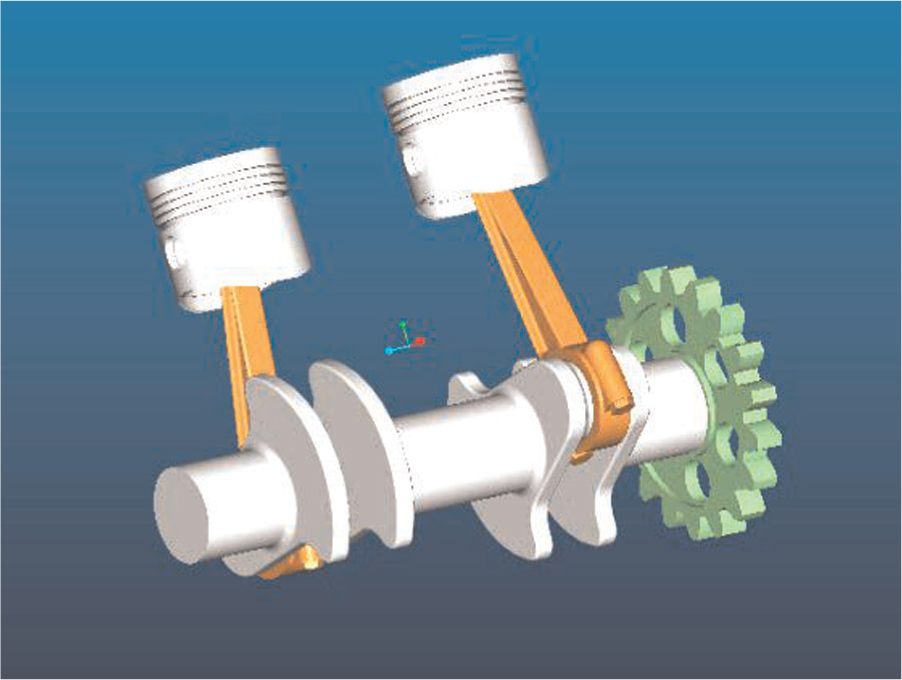
Engine model.
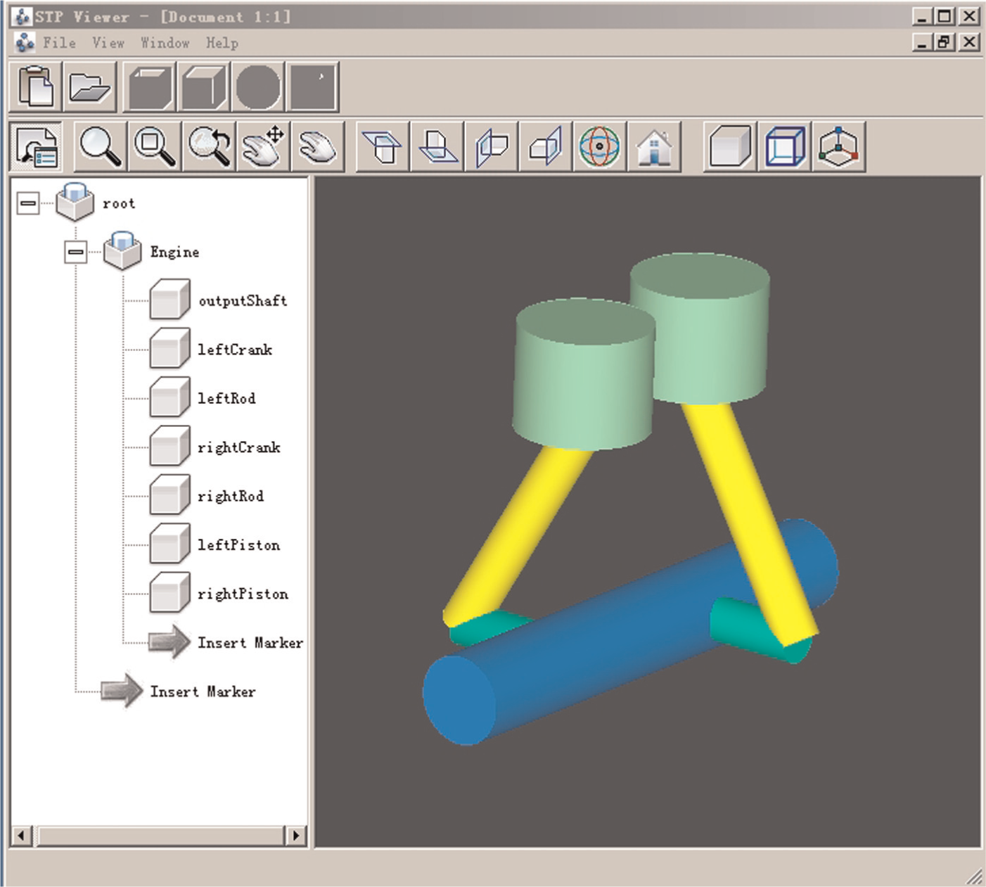
Initial CAD model.
Overview of the case study
As proposed by the professional designer, the selected industrial 2-cylinder engine is shown in Figure 19. The engine is comprised of an output shaft, two cranks, two rods and two pistons. The right gear part is not involved in this example. Note that the model in Figure 19 is not the initial CAD model generated from the SysML model, but the final CAD model after refinements on the initial CAD model as shown in Figure 20.
System structure modeling
A professional designer is invited to perform the task of system structure modeling for this engine. Before modeling, he sketches the rough physical structure, as shown in Figure 21. As evident from the figure, the engine structure is symmetrical in terms of left and right parts.
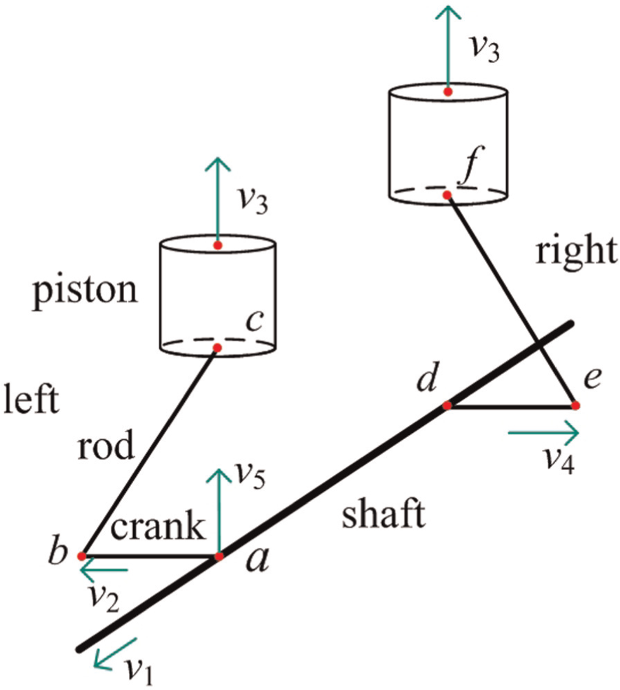
Initial sketch of the engine.
In the left parts, the bottom of the crank is in contact with a certain point a on the shaft, while its top point b connects with the bottom of the rod. Similarly, the top of the rod touches the bottom of the piston at point c. The top face direction of the piston is v3. The top direction v1 of the shaft is perpendicular to that of the crank, v2. The direction v5 (from point a to c) is the cross-product of v1 and v2. Note that the final structure would be unaffected if v1 and v2 point in opposite directions. Clearly, v3 and v5 are parallel. The parts on the right side are placed similarly.
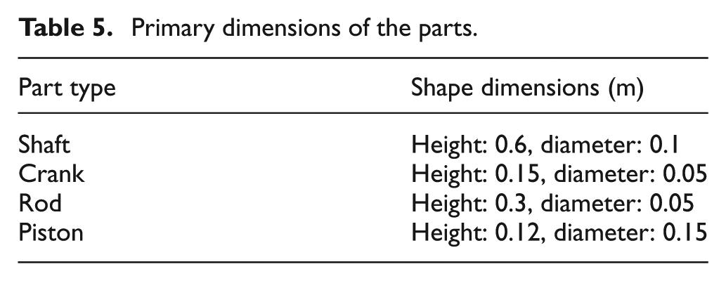
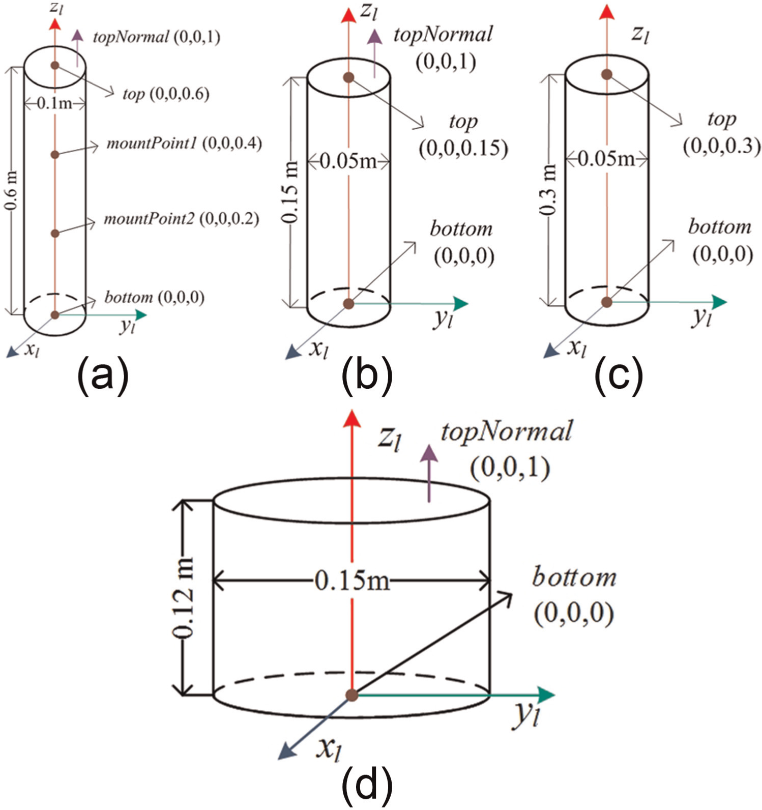
To model the preliminary layout in SysML, the designer models the shaft, crank, rod and piston parts first (i.e. type definitions). The cylinder shape is selected to represent the rough body for these parts. The dimension values are tabulated in Table 5. As the preliminary layout is obtained with spatial constraints, the relevant points and directions should be explicitly specified for these parts, too. They can be modeled as the interface features on parts using the basic geometric elements. Therefore, these parts are defined, as shown in Figure 22.
Primary dimensions of the parts.
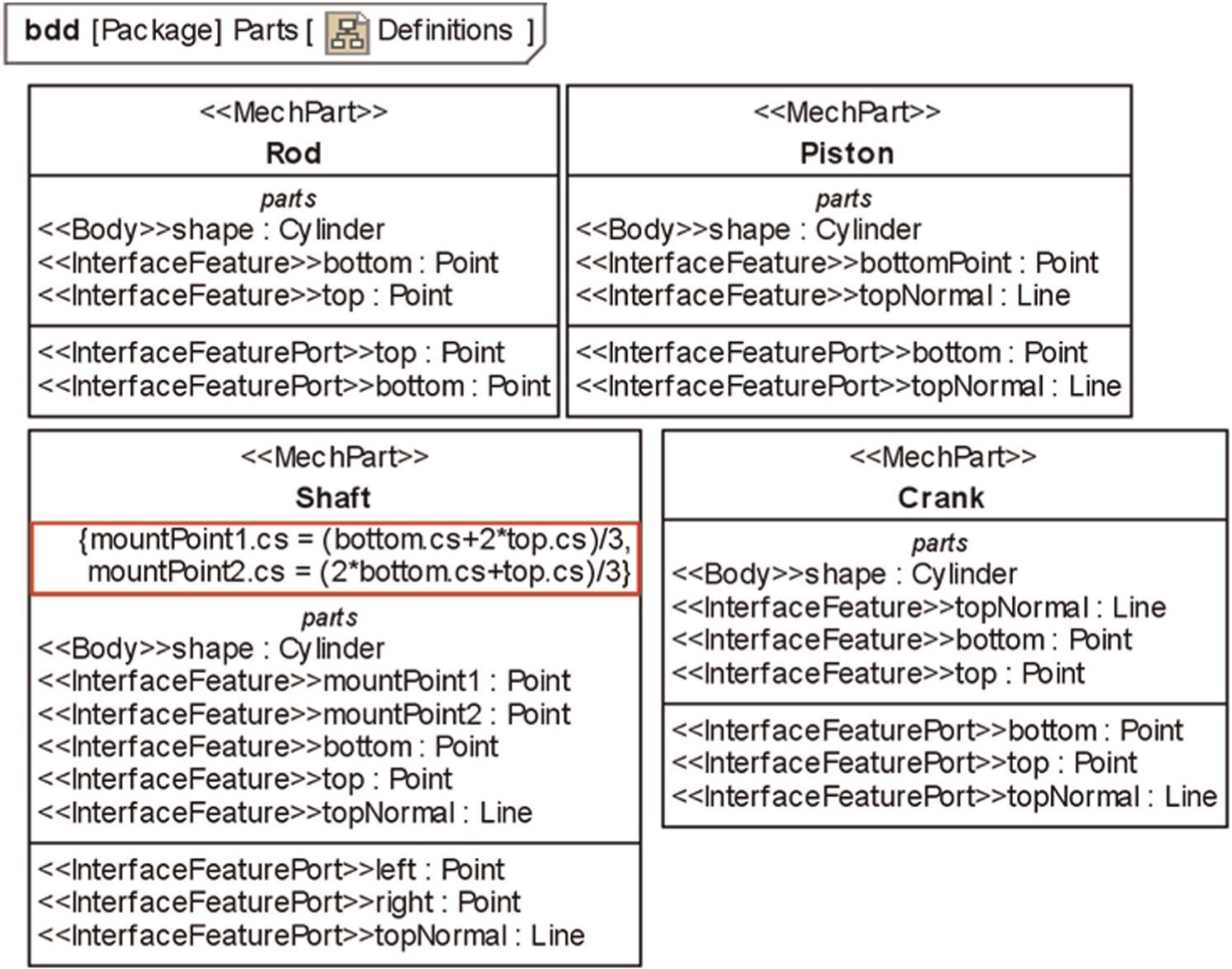
Part definitions.
Figure 22 shows that the shaft has five interface features, the mountPoint1 and mountPoint2 representing the points a and d in Figure 21. All the defined constraints for the example engine are tabulated in Table 6. These results show that only the points of both ends are explicitly provided for the cylinder shape (in Table 3). Hence, the shaft defines the constraints to describe how to derive mountPoint1 and mountPoint2 from the standard interface features, that is, top and bottom points. The direction v1 is represented by the topNormal of the shaft, one of the standard interface features formalized in Table 3. It should be noted that in the designer’s mind, points a and d are the trisection points of the shaft, so it is necessary to explicitly specify how to derive mountPoint1 and mountPoint2 from the regular interface features of the shaft part type (indicated by the red frame in Figure 22).
Constraints defined for the example engine.
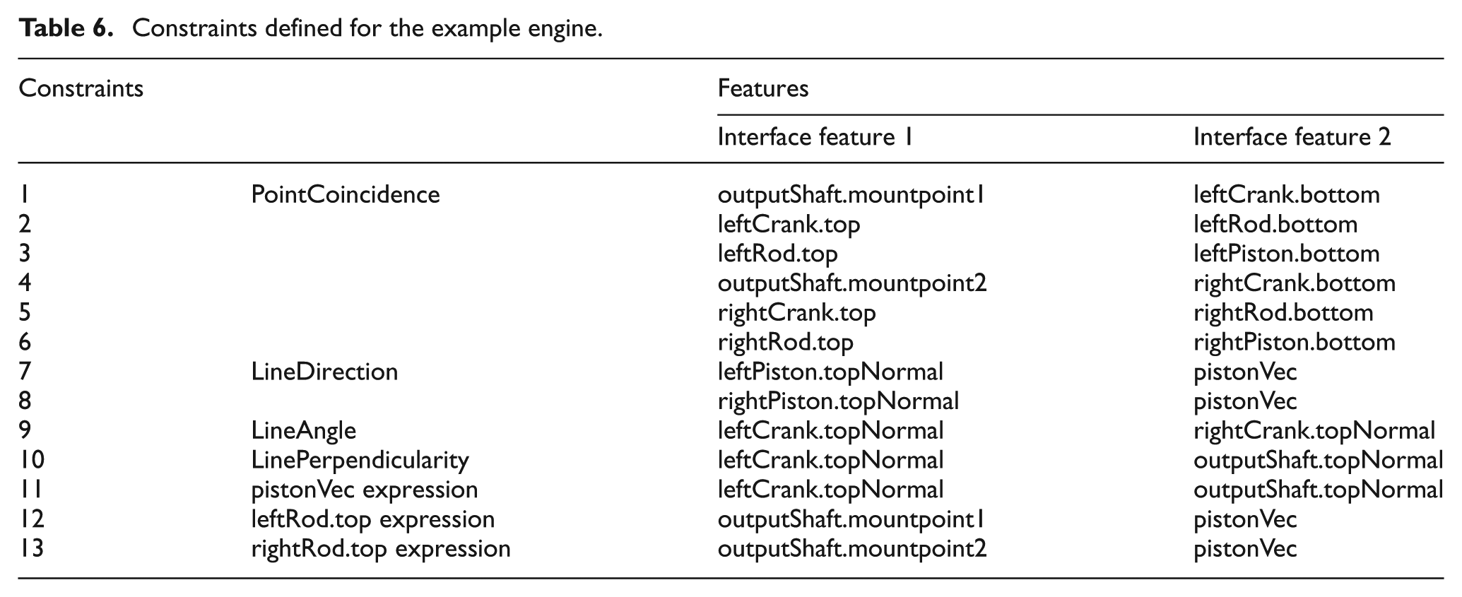
The structure of the engine is consequently defined, as shown in Figure 23. In addition to the part definitions, the engine structure includes six PointCoincidence constraints for points a to f in Figure 21. The LineAngle constraint specifies the angle between v2 and v4, and LinePerpendicularity specifies the relationship between v1 and v2. As the direction v5 is modeled by the pistonVec attribute, two LineDirection constraints are defined to set the direction v3 to pistonVec for both pistons. The distance from point a to point c is specified by the piston2shaft attribute. Then points c and f can be determined to constrain the tops of both rods, as shown in the constraints of the engine structure in Figure 23 (indicated by red frame in Figure 23). Finally, the internal structure of the engine is determined, as shown in Figure 24.
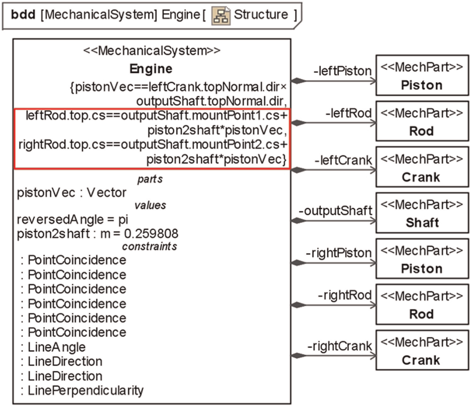
Structure definition of the engine.
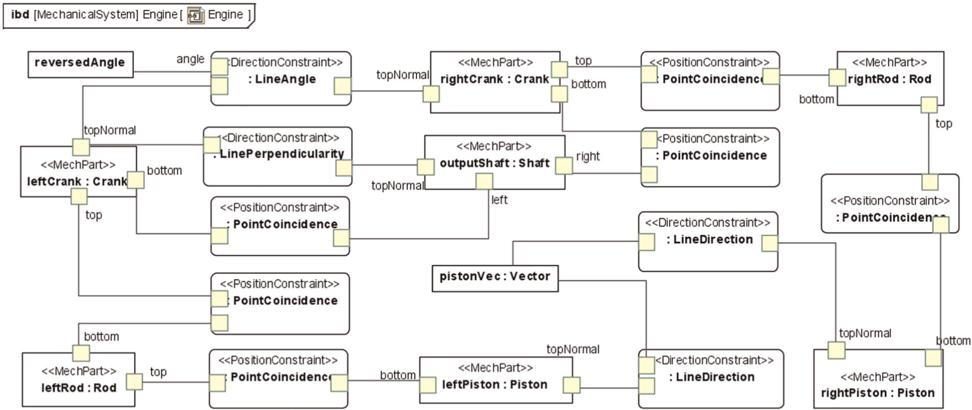
Internal structure of the engine.
Model transformation
The transformation execution (follows the steps in section “Integration framework,” as shown in Figure 12) is illustrated in Figure 25. The systems modeling step has been completed by the designer, as shown in Figures 22–24. Then, the engine model information is extracted by a plug-in (implemented by application programming interfaces (APIs)) and outputted as an XMI file. The second step, meta-modeling, is performed with the MOFLON tool, which supports meta-modeling and TGG specification in a uniform environment. The explanation of the TGG transformation is also available in the authors’ previous work.7,8
Model transformation by TiE.
In step 3 (described in section “Integration framework”), Java codes are automatically generated for the source meta-model, the target meta-model and the TGG specification defined in the MOFLON tool. The codes are then used within the TiE integration framework (enclosed by the red area in Figure 25) to perform the model transformation. As described in Figure 7, the TiE reads the source SysML model file (the result of step 1) as the input to perform the transformation process. The offline mode of the framework is activated so that the input and output model files are in the XMI format, as shown in Figure 25. Finally, the TiE tool executes the transformation to generate the EXPRESS model. Note that steps 2 and 3 are performed once beforehand so that only steps 1 and 4 are executed by designers in practice.
Detailed model generation
From the generated EXPRESS model, the B_Rep model is generated for all parts first, and then the transformation data are calculated for the final STEP-based CAD model. The entire process is executed automatically, with the calculations described below.
Part model generation
Two tasks are performed by the PMG for each part: (1) generating the B_Rep model with the specified shape parameters by instantiating the template; and (2) initializing the local coordinate values for the MI based on the shape parameters.
Taking the shaft part as an example, for the first task, its shape is shown in Figure 26(a). Driven by the dimension values in Table 5, the center of the bottom face is (0, 0, 0), that is, the origin point in the local environment, while that of the top face is (0, 0, 0.6). Hence, the B_Rep model is generated using the height (600 mm) and the radius (50 mm) values to instantiate the cylinder-typed template. Figure 27 lists some typical AP 203 entities (highlighted in red) to demonstrate the dimension settings. The B_Rep model can be generated similarly for other parts.
MI information of all part types: (a) shaft part type, (b) crank part type, (c) rod part type and (d) piston part type.
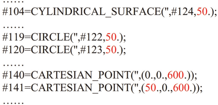
B_Rep model of the shaft part (partial).
The second task initializes the coordinate values for the employed interface features. With respect to the shaft part, the bottom is set to the origin (0, 0, 0), and the top, to (0, 0, 0.6). Hence, mountPoint1 and mountPoint2 of the shaft (defined in Figure 22) can be calculated and set to (0, 0, 0.4) and (0, 0, 0.2), respectively. The interface feature topNormal is a unit vector (0, 0, 1), indicated by the purple arrow in Figure 26(a). The MI of the other parts is also provided in Figure 26.
Transformation data calculation of the engine
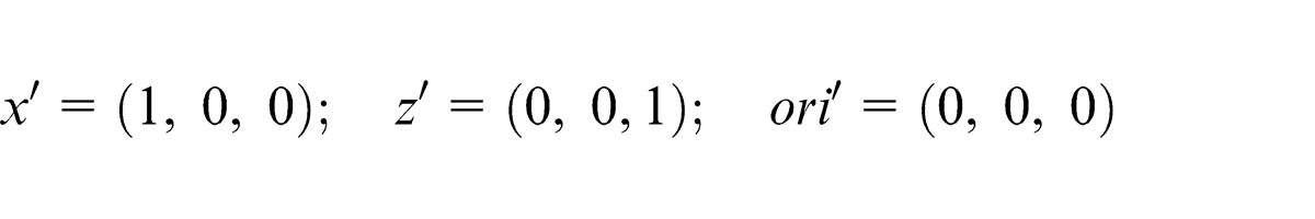
With the initial MI shown in Figure 26, the transformation data can be calculated for the parts based on the spatial constraints. The outputShaft part is selected as the base part to begin the calculations. According to the algorithm in Figure 17, it is clear that the base part is assembled without transformation. Therefore, this part can be directly inputted into the assembly environment, as shown in Figure 28(a), which also shows that the coordinate system of the shaft part type (shown in Figure 26(a)) is identical to that of the assembly. The transformation data are thus
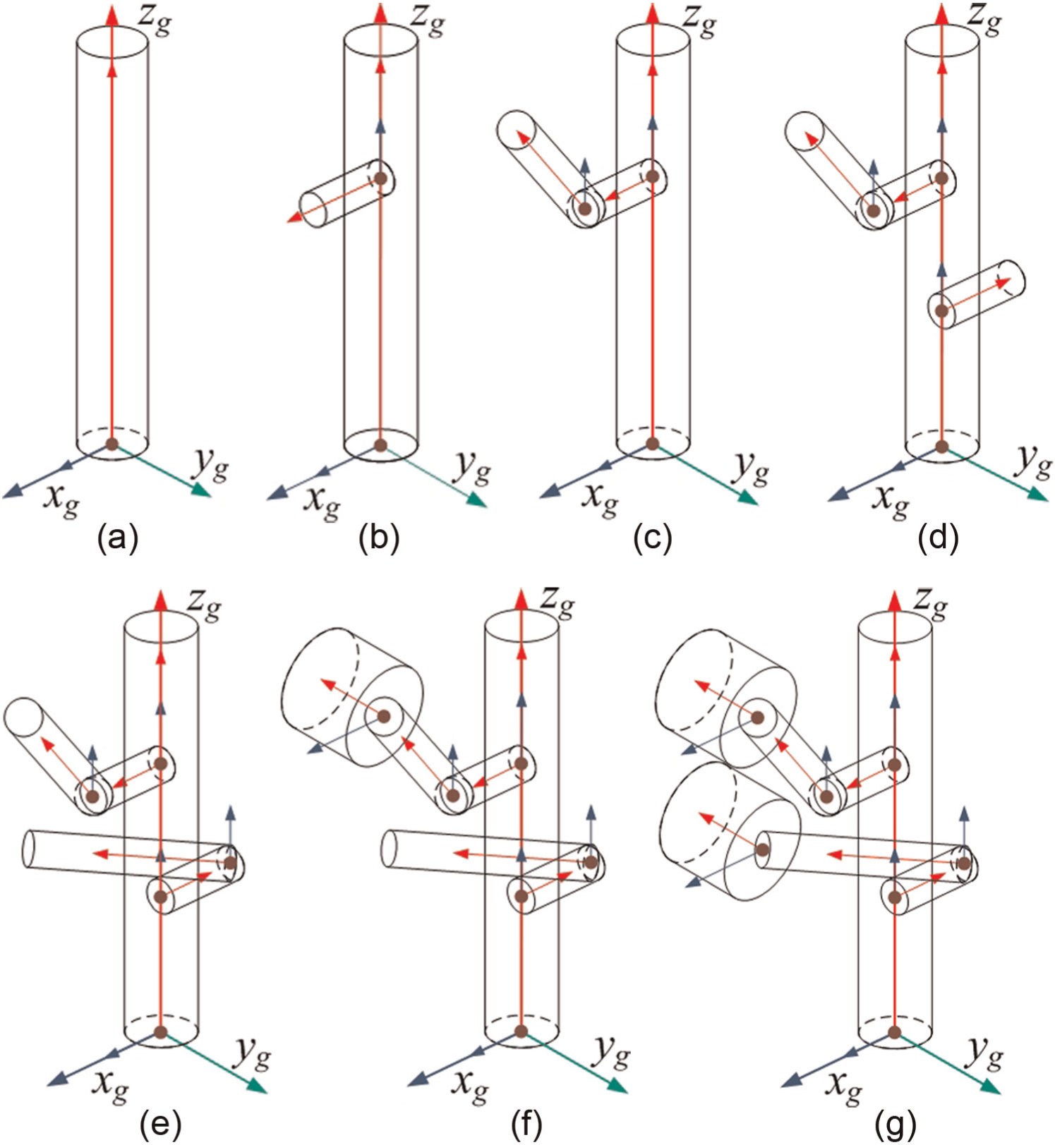
Calculation steps for all parts. (a) output Shaft; (b) left Crank; (c) left Rod; (d) right Crank; (e) right Rod; (f) left Piston; (g) right Piston
The next part is the leftCrank because of the direct spatial constraint between it and the outputShaft. The bottom of it coincides with mountPoint1 of outputShaft; the topNormal attributes of both parts are perpendicular. Suppose the axis xl (shown in Figure 26(b)) of the leftCrank is parallel to zg . Then, this part can be inputted into the assembly environment, as shown in Figure 28(b). Because xl and zl are parallel to zg and xg , respectively, the transformation data are
These data can be derived for other parts in the same manner by analyzing the spatial constraints. Figure 28 provides the transformation data for all parts by showing in the calculation sequence, which finally generates the assembly structure. Indeed, the calculation process must determine the transformation matrix for each part, as detailed in Appendix 2.
Assembly model generation
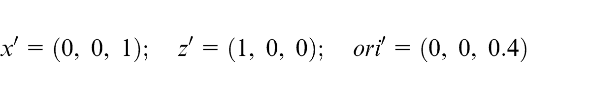
After the transformation data are obtained, the final task is generating the initial CAD model as an AP 203-based STEP file. Based on the provided templates shown in Appendix 1, the assembly model generation is straightforward. The final structure of the STEP file is abstracted in Figure 29(a). Specifically, the relation definition of the outputShaft part is highlighted in Figure 29(b), which is composed by the entities specified by the relation definition sub-structure in Appendix 1. Note that the transformation data obtained from the calculation process are represented by the entities “#1010,”“#945” and “#946,” The detailed definitions of the entities can be found in ISO 10303-203:1994, 19 AP 203 47 and ISO 10303-42:1994. 49
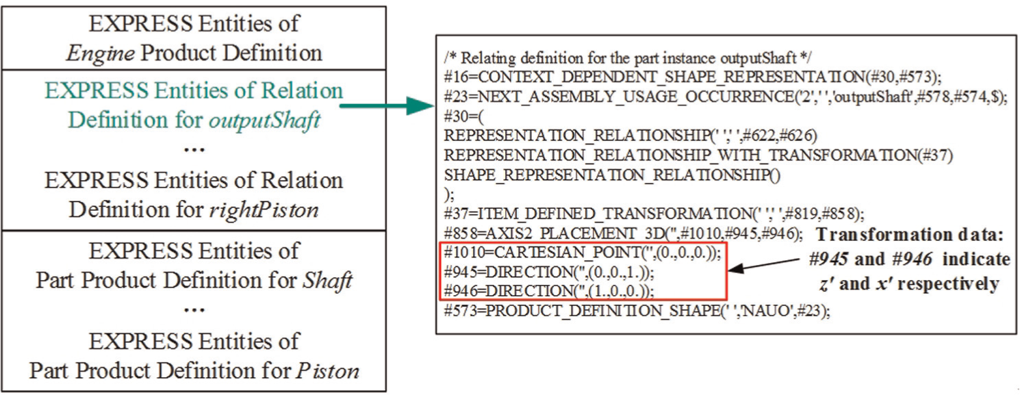
Structure of the engine assembly model: (a) general structure of engine and (b) relating definition of the output shaft part.
Assembly model.
To automate the generation process, the authors developed a tool that realizes the PMG function, the transformation data calculation and the assembly model generation tasks. This tool is implemented with the Perl script language because the STEP file is based on text, and text-handling is the precise capability of Perl. Based on this tool, the B_Rep models are constructed for the parts, and the transformation data are calculated after the EXPRESS model (in XMI) is inputted. Then, the AP 203-based STEP file is generated with the template-based method. Finally, the STPViewer tool 50 is used to open the assembly model, as shown in Figure 20. The model can then be imported into commercial CAD systems to enable the following development. The generated assembly model is validated by the professional designer. The designer is attentive to the automated generation of the assembly model because of two benefits. First, it offers an initial CAD model for the subsequent development. The second benefit is that the visual representation of the structure improves the communication effectiveness among different engineers. 18
Discussion
In this section, the characteristics of the proposed method are analyzed and compared with the existing methods, particularly the approach in Hamid, 9 because the two methods share the same domain. The following three aspects are considered: (1) the representation capability of the system model, (2) the stability of the system meta-models and (3) the extendibility of the approach. These aspects are the critical factors that impact the applicability of the method. After analysis, the limitations of the proposed approach are discussed.
Analysis of the characteristics of the method
Representation capability
During the conceptual design stage, the designers specify the rough component shapes for the preliminary shape design and then decide how to place them into the general position to guarantee that the desired functions will perform correctly. The overall layout design and the spatial compatibility might cause unexpected system behavior. However, it is difficult for designers to determine the final complex shape at an early design stage based on the rough information of a high-level abstraction. Moreover, the task of performing shape design is particularly suited to CAD tools and must be addressed at the detailed design stage because the shape design is not the focus of the conceptual design.
Therefore, elementary shapes are used in this study to support the conceptual design. The part profile allows designers to customize the characteristics of the interface features and parts to specify the different parts of the system design, while the interface feature configuration provided by the constraint profile is used for implementing the preliminary layout design. Because the arbitrary shapes, such as freeform surfaces, are beyond the considerations of conceptual design, they are excluded from the systems modeling in this study. This rationale is also understood by the professional designer.
Existing approaches focus on how to relate the existing models at different stages. The models of conceptual design were generated by representing the selected properties of a specific CAD model, which was directly coupled with the SysML model. Therefore, the representation capability of the SysML model was limited to the existing CAD models. This limitation also exists in the approach proposed in Hamid 9 because the SysML profile is based on a specific CAD platform. These previous approaches implicitly realize, to some extent, a bottom-up design methodology. In contrast, the meta-models in this study are constructed with high-level abstraction to support a top-down design. In this respect, the proposed method should be an indispensable supplement to the existing methods.
Stability
The stability of the system meta-models is specified to the extent to which the meta-models can remain stable when the concepts of the corresponding domain change. Given that the model integration is built with the model transformation tool, any change in meta-models would generate updates in the transformation logic. Therefore, modifications of meta-models should be minimized.
To overcome this stability issue, direct mapping between SysML and a specific CAD platform was not introduced in the meta-models. The general concepts used in the mechanical systems modeling and the EXPRESS language mapped with SysML are independent of any CAD platform. In fact, as a technical standard, the existing STEP files are supported even if the concepts of a specific CAD platform change. Therefore, the proposed method is decoupled from the specific CAD platforms. For the methods described in Hamid 9 and Bajaj et al., 11 maintaining the stability of the system meta-models is difficult after the meta-model concepts change on a specific CAD platform because they are directly mapped to the specific CAD platform used.
Extendibility
Extendibility is the ease of adapting the system structure to changes in system specifications. Although the output is the STEP file, the proposed method is easily extended to support model generation for a specific CAD platform using additional meta-models definitions rather than directly changing to the existing meta-models. Generally, for the platform-specific assembly constraint between parts, new meta-models can be added in a separate SysML profile to represent these concepts. Therefore, the mapping between each item and the existing interface feature configuration can be constructed in the constraint profile. The extension to a specific CAD platform is thus achieved with both the additional meta-models and the APIs of the specific CAD platform.
The approach described in Bajaj et al. 11 supports several CAD platforms, such as NX, Pro/E and CATIA, while only the Solid-Edge platform is accessible in the approach described in Hamid. 9 In the approach proposed by Hamid, 9 extending the model integration process for another CAD platform usually requires redefining all meta-models and the transformation logic. For our approach, the system meta-models are reusable, and only the incremental meta-models are required to switch to a different CAD platform. Note that the platform-specific API support is indispensable to all approaches.
Limitations of the proposed method
This section describes the limitations of the proposed method. The first limitation involves the construction of the new template for B_Rep models. Usually, the new template can be easily constructed based on existing templates. However, the generation of a new part template with concave interface features, for example, a hole and a slot, cannot be directly performed. This issue with a new part template can be fixed by first generating a constructive solid geometry model and then transforming it into the B_Rep model.
The second potential limitation of the proposed method is the lack of intuitiveness for systems modeling. The proposed method might be prone to errors in the placement of the interface feature configuration between parts required to complete the overall layout design. Similarly, the proposed method must predefine as many interface features and interface feature ports as possible for the parts to facilitate the interface feature configuration. For instance, it is rational to place a Block part, so that it touches another part on any side such that an interface feature must be assigned for each side of the Block part. However, it might be difficult to distinguish these interface features in the case of a large number of interface feature ports. This ambiguity is caused mainly by the lack of a three-dimensional (3D) visualization tool for the system structure representation in this phase. 51 Consequently, introducing 3D visualization tool as the assistance for systems modeling is valuable because a modeler can obtain an initial perception of the structure. 52 Currently, developing such a tool with the existing SysML modeling platforms is limited due to the lack of platform API. A reasonable method recommended by the professional designer is using simple shape types to represent the system parts. The designer proposed containing a single body for a part because a part with multiple bodies hampers understanding.
The third potential limitation of the proposed method is the inability to represent other mechanical design intents, 53 such as constraints that might be specified in the conceptual design, because only geometry-related information is considered in this study due to the requirements of the STEP AP 203 file regarding the representation of the product shape and the assembly structure. However, it is feasible to represent other mechanical design intents in the system meta-models with the extension capability of SysML.
As a supplement to existing approaches, combining the CAD model generation approach in this study with the SysML model generation and consistency maintenance approaches described in Hamid 9 and Bajaj et al. 11 develops an integrated model integration solution that offers higher design efficiency.
Conclusion and future work
In this article, an approach for generating the initial CAD model based on the SysML model is proposed to narrow the gap between the conceptual design phase and the detailed design phase. The relevant contributions of this article are as follows:
A geometry-related profile is proposed, which contains the part subprofile and the constraint subprofile. By adding the interface features to the parts and the constraints of the system, the system structure can be easily modeled by the system designer.
A TGG-based method is proposed for generating the EXPRESS-based model from the SysML-based system structure model. In this manner, the proposed approach enables the decoupling of the relationship from a specific CAD platform, and thus, the system meta-models can remain stable.
A template-based method is proposed to generate the initial CAD model in STEP file format. The method is based on the existing templates and reuses knowledge. Such a CAD model is used as the starting point for constructing the subsequent detailed design.
Generating the CAD model as a STEP file enables the following development to be conducted directly and precisely. We believe that one potential benefit of the proposed method is the ability to reveal hidden problems because it enables a more intuitive means of analyzing the system structure model. By maintaining the relationship between the system structure model and the initial CAD model, the potential advantages include better traceability, updateability and consistency for multi-domain model integration. In such scenarios, establishing active linkages among different models is critical to improve these characteristics and merits further research.
Providing a rough dimensional layout is important for assessing a system structure model. The spatial relationships between system components are also crucial for the domain engineers, although they could be typically overlooked during the conceptual design. Therefore, such information should be introduced in a system structure model. Consequently, the modeled system structure can be evaluated in terms of the spatial relations because they are prerequisites to guarantee the occurrence of specific physical phenomena.
Future work will mainly focus on overcoming the above-mentioned limitations. To support systems modeling, additional technologies, such as object constraint language, are encouraged to constrain and normalize the modeling activities to ensure quality and efficiency. As the STEP standards evolve, the updated semantic information should be integrated using additional system meta-models. SysML-based reasoning is another promising research field. The extension mechanism offers a significant advantage for SysML, which can be used to define specific stereotypes to facilitate the modeling of physical semantics. Hence, SysML-based reasoning becomes possible to support the conceptual design and the evaluation of concept variants.
Footnotes
Appendix 1
Appendix 2
Acknowledgements
The authors wish to acknowledge the anonymous reviewers for their helpful suggestions. We are impressed by the rigorous proofreading and highly appreciate your hard work.
Declaration of conflicting interests
The authors declare that there is no conflict of interest.
Funding
The authors are appreciative of the support received from the NSF of China (61173126, 61163016), the 863 High-Technology Project of China (2011AA100804) and the Zhejiang Provincial Natural Science Foundation of China (R1110377, LZ12F02001).