
Abstract
An innovative welding methodology, defined as double-side friction stir welding, was developed in order to obtain joints in 2-mm-thick sheets in AA6082 aluminium alloy. Such approach consists in performing the friction stir welding process on both sheet surfaces: the first welding operation is followed by a second one performed by putting the rotating tool in contact with the sheet surface opposite to the one welded by the first pass. The effect of the welding parameters, tool configuration and sheet positioning on the mechanical properties, microstructure and post-welding formability was analysed and discussed in detail. In order to evaluate the advantages offered by the new welding methodology, the experimental results obtained using the double-side friction stir welding were compared with those given by the conventional process.
Keywords
Introduction
Tailor-welded blanks (TWBs), obtained by welding two or more sheets, also of different metals, thicknesses and/or coatings, to produce an assembly that can be subsequently deformed, can be used in several industrial fields, such as in the car panel manufacturing. TWB technology gives automotive designers the opportunity to selectively vary the body-panel thickness in critical areas as well as to optimise the use of materials. 1
The development of TWBs began with steel sheets, but the need to minimise vehicle weight and harmful emissions into the atmosphere has led many car manufacturers to replace steels with aluminium alloys. However, sound TWBs in Al alloys are difficult to obtain due to the low weldability characterising such alloys as fusion welding methods, such as laser welding, are taken into account.The common difficulties in laser welding of aluminium alloys include porosity, hot cracking, underfill formation, poor coupling of the laser due to the high reflectivity of the metal and degradation of the material properties in the heat-affected zone (HAZ).2–5 Despite the several advantages offered by laser beam welding technology on aluminium alloys, the welding process suffers from seam imperfections such as notches or holes in the seam which reduce the mechanical properties of the joint. 6
In order to overcome such drawbacks, friction stir welding (FSW), a solid-state welding technique, can be used.7–10 In FSW, the blanks are joined by the action of a rotating tool with a pin getting in contact with the top surface of the sheets and then moving along the welding line with a proper tilt angle. The combined effect of tool rotation and translation involves heat generation by friction between tool and sheets, inducing a strong plastic deformation of the workpiece by promoting its complex mixing across the joint.8–12 As a consequence, a plasticised region is created around the tool so that the material is extruded from the leading side (advancing side (AS)) to the trailing side (retreating side (RS)) of the weld. Kumar and Kailas 13 investigated the mechanism of weld formation and the role of FSW tool in such mechanism. In particular, they observed two different types of metal flows: the pin-driven flow and the shoulder-driven one, respectively, transferring the metal by layer and by bulk. As far as thin sheets are concerned, Simoncini and Forcellese 14 demonstrated that a pinless tool can be effectively used in FSW. In such case, the welding joint is obtained by means of the shoulder-driven metal flow alone.
Notwithstanding the advantages offered by FSW, the weld could not be able to reach, without failure, the high strain levels occurring during secondary forming processes in the obtaining of complex shape sheet parts. The weld seam itself does not reduce formability as much as the presence of the geometric discontinuity caused by the thickness gradient. 4 In addition, formability of the FSWed joint is limited by the small clearance between the bottom side of the pin and the backing plate necessary to avoid their contact during welding. This involves the formation of a small geometric discontinuity into the joint, located at the bottom surface of the sheets, that causes a local increase in the intensity of the stress field and acts as a notch; such drawback was observed by Forcellese et al. 15 on FSWed AZ31 magnesium alloy sheets. The high local stresses lead the FSWed joints to fail more quickly than the base material (BM). Such phenomenon becomes more marked as the notch is subjected to a severe tensile stress state, involving a quicker crack propagation. A further drawback of aluminium alloy FSWed joints is the non-uniformity of both precipitation and grain size, occurring along the sheet thickness and perpendicularly to the welding centreline; such behaviour can be attributed to the inhomogeneous distribution in temperature, strain and strain rate in the stirred and thermo-mechanically affected zones (TMAZs), as well as in temperature in the HAZ. 8 An improvement in ductility and formability of FSWed joints would be necessary in order to increase the number of potential applications. 16
A new approach, developed in order to improve joint formability, consists in carrying out the FSW process on both sheet surfaces; in particular, the first welding operation is followed by a second one performed by putting the rotating tool in contact with the sheet surface opposite to the one welded during the first pass. Such an innovative methodology, that is here defined as double-side friction stir welding (DS-FSW), offers the advantage represented by the closure, by means of the second welding operation, of the geometric discontinuity produced by the first one; furthermore, the proposed approach allows obtaining more uniform values of hardness and recrystallised grain size across the welded zone as compared to the conventional FSW, as shown by Cabibbo et al. 17 Such improvement in the joint quality is very attractive as the assembled blanks have to be subjected to post-welding forming operations.
Many studies have been performed on FSW to analyse the effect of the tool geometry, sheet positioning and process parameters on the mechanical properties, microstructure and formability of joints. Simoncini and Forcellese 14 showed that the tool configuration, rotational speed and welding speed critically affect mechanical properties, microstructure and formability of FSWed joints in AA5754 thin sheets. Sato et al. 18 evaluated the formability of FSWed sheets in AA5052 alloy by studying the relationship between the fracture limit in the plane-strain deformation and microstructure. Kim et al. 19 experimentally and numerically demonstrated that the formability of FSWed AA6111 alloy sheet, evaluated by means of tensile test, hemisphere dome stretching test and cylindrical cup drawing test, is affected by the welding line direction. Hirata et al. 16 studied the influence of FSW parameters on the grain size of the stir zone and the formability of FSWed 5083 Al alloy. Jamshidi Aval et al. 20 have analysed microstructures and mechanical properties in similar and dissimilar FSW of AA5086-O and AA6061-T6 using a thermo-mechanical model and experimental observations. Also, Lee et al., 21 experimentally and numerically investigating formability, of FSWed TWB automotive sheets in five different materials, showed that formability, as well as ductility and strength, was dependent on the weld zone line arrangement. Biswas et al. 22 studied the effect of both the tool pin geometry and tool rotation and welding speeds on the mechanical properties of FSWed joints in aluminium alloys. Few experimental works are nowadays available in the literature on multipass FSW. In particular, Leal and Loureiro 23 performed four overlapping passes on AA5083 and three overlapping passes on AA6063 in order to eliminate any defect generated by the first pass. Brown et al. 24 investigated how the multipass FSW of AA7050 influences changes in weld property, weld metallurgy and process response parameters. As far as DS-FSW is taken into account, only one article by the authors, concerning micro-mechanical and microstructural results, has been published. 17
Within the above-mentioned framework, this work aims at studying the innovative welding methodology, defined as DS-FSW; such investigation was carried out on 2-mm-thick sheets in AA6082 aluminium alloy. The effect of the welding parameters, tool configuration and positioning of sheets on the macro-mechanical properties, microstructure and post-welding formability was analysed and discussed in detail. In order to evaluate the advantages offered by the proposed methodology, the experimental results provided by the DS-FSW were compared to those given by the conventional FSW process. Micro-mechanical properties, determined by nanoindentation, and microstructure inspections of conventional- and DS-FSWed joints were performed and reported in Cabibbo et al. 17 in order to correlate formability to hardness and local elastic modulus.
Experimental procedures
Welding settings
FSW experiments were carried out using a computer numerical control (CNC) machining centre; the material investigated was AA6082 aluminium alloy, supplied, in the T6 temper state, in the form of 2-mm-thick sheets. Tools in H13 steel, in the pin and pinless configurations, were used. The conical pin tool geometry was characterised by a shoulder diameter equal to 12 mm and cone base diameter and height of the pin of 3.5 and 1.7 mm, respectively, with a pin angle of 30° (Figure 1(a)). As far as the pinless tool was considered, a 19-mm-diameter rotating tool was used (Figure 1(b)). All the welding experiments were carried out with a nuting angle equal to 2°.
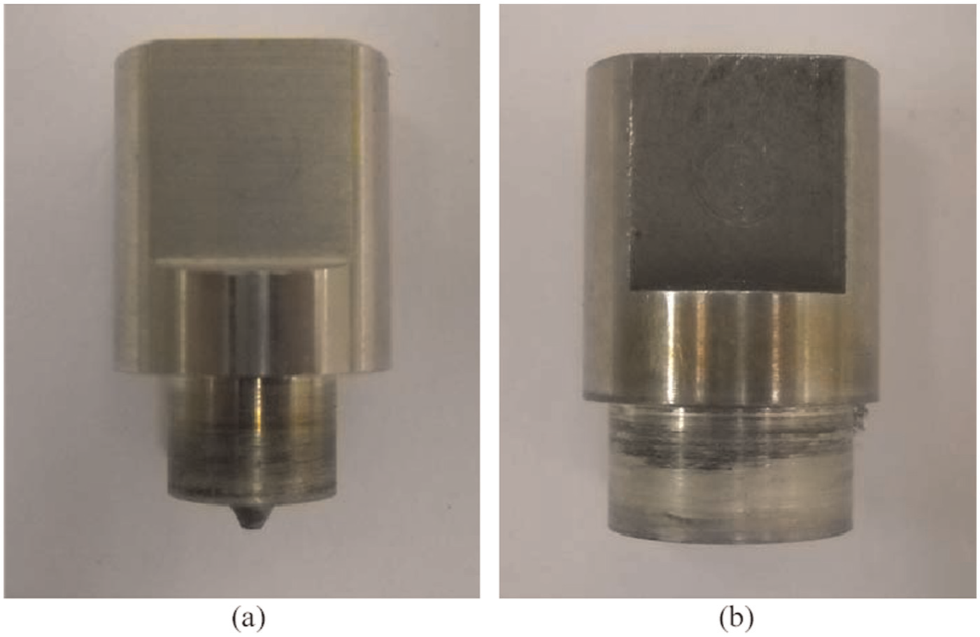
Tools used in friction stir welding: (a) ‘pin’ configuration and (b) ‘pinless’ configuration.
FSW was performed according to two different methodologies. In the former, the conventional single-pass welding operation was carried out, while in the latter, the FSW was performed on both sheet surfaces (DS-FSW). In particular, the first welding operation was followed by a second one performed by putting the rotating tool in contact with the sheet surface opposite to the one welded during the first pass. Two different sheet positions with respect to the welding tool were investigated: (1) AS–AS, in which the sheet placed in the AS during the first pass was maintained in the same side also during the second pass, and (2) AS–RS, in which the sheet, placed in the AS during the first pass, was placed in the RS during the second one. The effect of tool configurations on the quality of the DS-FSWed joints was also analysed. Table 1 summarises the different tool configurations and sheet positions used in the experiments.
Different tool configurations and sheet positions with respect to the welding tool used in the conventional- and DS-FSW.
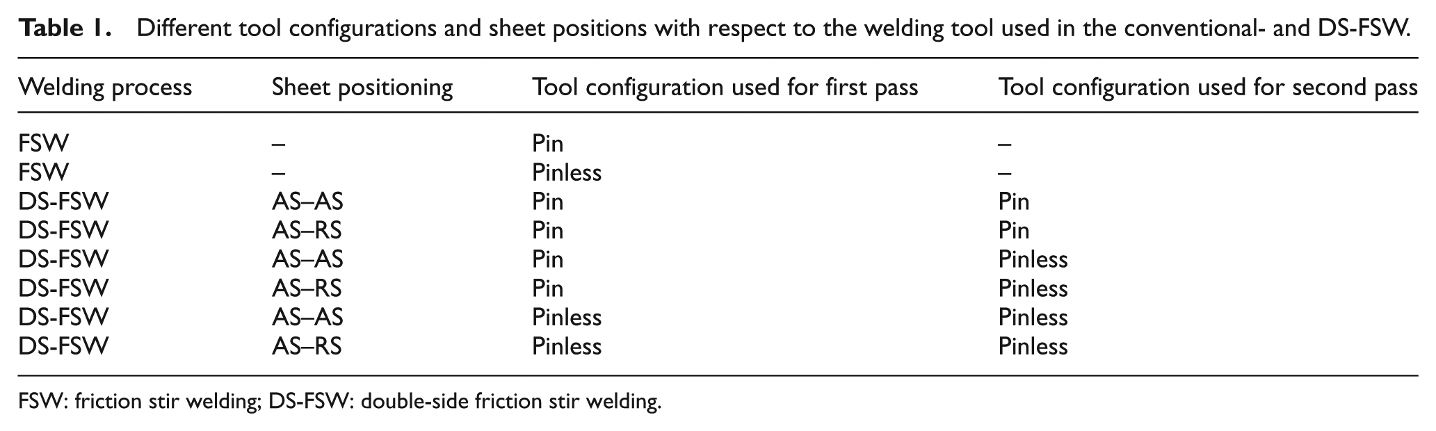
FSW: friction stir welding; DS-FSW: double-side friction stir welding.
The blanks, 180 mm in length, 85 mm in width and 2 mm in thickness, were FSWed with the welding line perpendicular to the rolling direction.
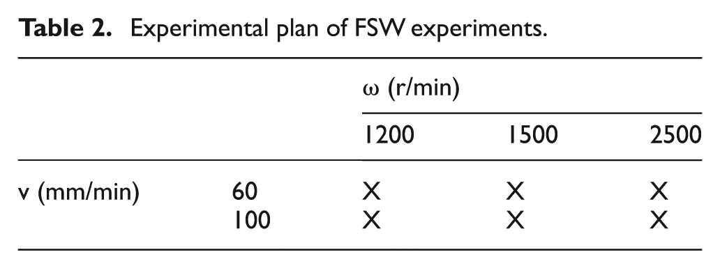
In order to investigate the effect of the process parameters on the conventional- and DS-FSW, the experiments were performed using constant values of the rotational speed (ω) and welding speed (v), according to the experimental plan reported in Table 2.
Experimental plan of FSW experiments.
Different tool sinking values were imposed as a function of the welding processes shown in Table 1. In particular, the conventional FSW was carried out using a tool sinking of 0.2 mm, while the DS-FSW was performed with a sinking of 0.15 mm in the first pass and 0.05 mm in the second one. Such values were chosen since preliminary tests, carried out using different tool sinking values, showed the need to perform the second pass with a sinking lower than that of the first one in order to prevent the occurrence of fracture.
Microstructural analysis
Microstructure of FSWed joints was investigated by means of polarised light microscopy (POM); to this purpose, a Reichert-Jung™ MeF-3® microscope was used. The grain size was measured using the intercept method according to the American Society for Testing and Materials (ASTM) standard E112. In particular, the same area was examined using different images obtained by tilting the sample of an angle equal to 30° in order to distinguish grain from subgrain boundaries. Sample surfaces were polished and etched, for few seconds, using a solution consisting of 10 mL acetic acid, 6 g picric acid and 10 mL distilled water, in 100 mL ethanol.
Uniaxial tensile tests
The mechanical properties of the welded joints were evaluated by means of tensile tests at room temperature; specimens with the loading direction perpendicular to the welding line, machined from the welded blanks, with the gauge length equal to the shoulder mark, were used. The tests were performed according to ASTM E8/E8M and BS EN 895.
The results were plotted as nominal stress (s) versus nominal strain (e) curves by which the ultimate values of tensile strength (UTS) and elongation in percentage (UE) were derived. At least three individual tests were performed at each testing condition.
Formability tests
Formability of the conventional- and DS-FSWed AA6082 sheets was evaluated, at room temperature, by analysing the results given by the hemispherical punch test; they were carried out according to International Standard ISO 12004. The equipment used for the experimental tests consisted of a die, a blank holder and a hemispherical punch with a diameter of 30 mm. The tests were performed, with a punch speed of 0.1 mm/s, until the onset of necking. At least three individual tests were carried out for each process condition.
As a preliminary formability index, the value of the limiting dome height (LDH) was measured. To this purpose, samples, with a width-to-length ratio equal to 1 (100 mm × 100 mm), were clamped and deformed.
A more accurate evaluation of formability was obtained through the determination of the forming limit diagram (FLD). The hemispherical punch tests were performed using samples with width-to-length ratios varying from 1 (100 mm × 100 mm) to 8 (12.5 mm × 100 mm). For the base alloy, the length side was parallel to the rolling direction; concerning the welded samples, the length side was parallel to the welding line which was located in the central zone of the sample.
The hemispherical punch test on the welded blanks was carried out according to the different sample arrangements shown in Figure 2; in such scheme, ‘surface 1’ represents the top surface of sheets in contact with the shoulder during the conventional FSW or during the first pass of DS-FSW. By taking surface 1 as a reference, the B and T arrangements were obtained by placing the surface 1 in contact (Figure 2(a) and (c)) and countered (Figure 2(b) and (d)) with the punch, respectively.
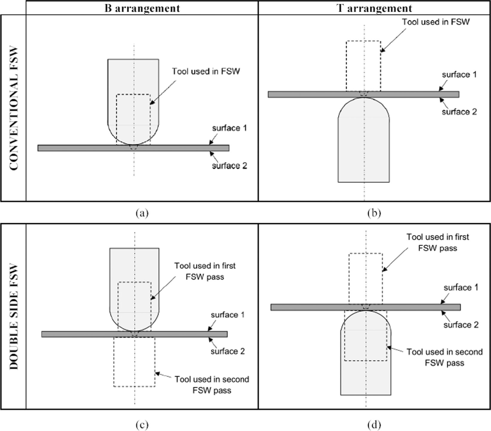
Different sample arrangements for hemispherical punch tests. B arrangement: “surface 1” in contact with the punch.T arrangement: “surface 1” countered with the punch.
In order to determine the strain distribution after testing, the surface of each sheet sample was meshed using a regular line grid with 1.5 mm in line distance. An accurate image analysis system was used to evaluate the major (ε1) and minor (ε2) strains.
Results and discussion
Mechanical properties of joints
Figure 3 shows typical nominal stress versus nominal strain curves of FSWed joints in AA6082 obtained under different values of the rotational speed and welding speed. Irrespective of the welding condition, it can be seen that, for a given strain, the s value of the base AA6082 alloy is higher than the one of the FSWed joints. Such behaviour is due to the softening caused by the heat generated during the welding process, which mitigates the strengthening produced by the T6 treatment responsible for the higher strength of the BM. Furthermore, the joints ductility is systematically lower than the BM one, irrespective of the welding parameters and process methodology, according to the results obtained by Rodrigues et al. 25 on thin friction stir welds in AA6016, and by Simoncini and Forcellese 14 on FSWed joints in AA5754 thin sheets.
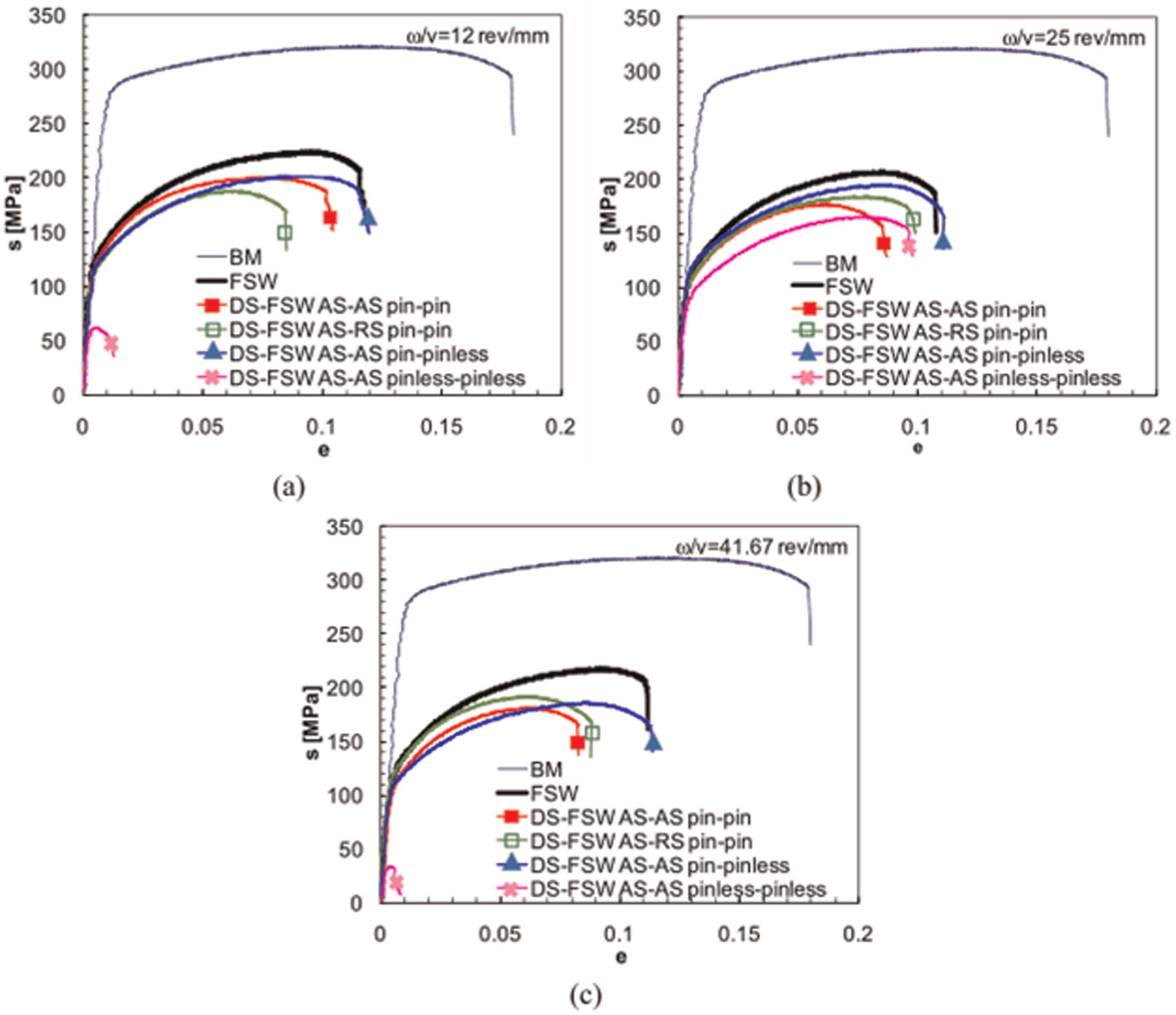
Typical flow curves of joints in AA6082 obtained by conventional FSW and DS-FSW using different welding parameters and tool configuration: (a) 1200 r/min − 100 mm/min, (b) 1500 r/min − 60 mm/min and (c) 2500 r/min − 60 mm/min.
In general, in terms of both the ultimate values of tensile strength and elongation, the conventional FSWed joints show a tensile behaviour better than the one exhibited by the DS-FSWed joints. Such discrepancy can be attributed to the different tool sinking imposed in the two different welding methodologies used. Actually, the conventional FSW process requires a high sinking value in order to generate the frictional heating allowing the material flow necessary to obtain sound joints, according to Mishra and Ma. 8 As far as the DS-FSW is concerned, the use in the first pass of the same tool sinking of conventional FSW produces a step in the blank surface that acts as a notch during the second pass; such stress intensity factor leads to the formation of macroscopic fracture surfaces. Therefore, in order to avoid the occurrence of such a defect, the sinking applied during the first pass in the DS-FSW must be lower than that used in the conventional FSW process. The tool sinking value imposed in the second pass has to be further decreased in order to reduce the formation of defects on the surface 1 shown in Figure 2.
The pinless–pinless configuration, obtained using the pinless tool in both passes of the DS-FSW, has provided the worst tensile results; in particular, while the AS–AS sheet position has usually given joints with low mechanical properties, the AS–RS position did not allow the obtaining of sound welds.
The mechanical behaviour strongly improves as welding is performed using the pin–pinless configuration, with ductility levels similar to the ones showed by the conventional FSWed samples. Such results are confirmed by analysing the fractured tensile sample shown in Figure 4; it also shows the occurrence of fracture in the HAZ, in the RS of the welded sample.
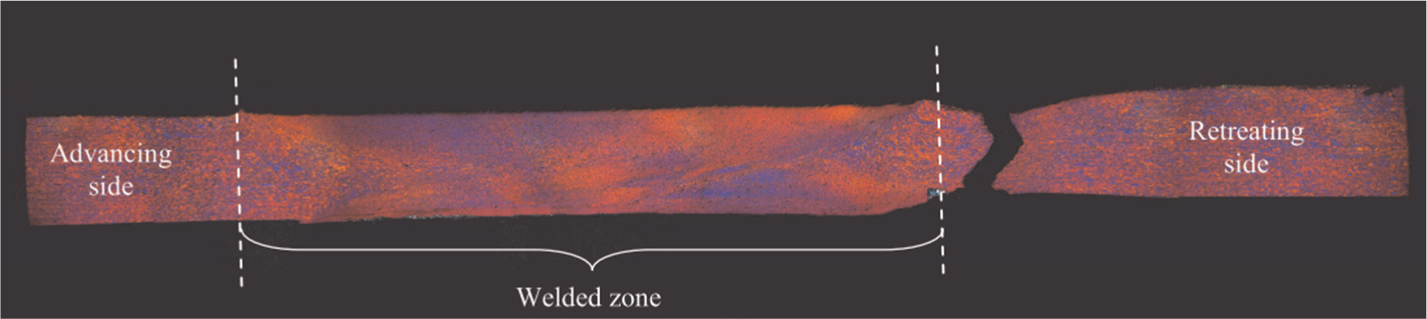
Macrostructure of a fractured tensile sample along the loading direction obtained by DS-FSW.
As a general trend, for a given tool configuration and sheet positioning, the tensile properties of the joints are slightly affected by the rotational and welding speeds investigated; this behaviour is not followed by the DS-FSW in the pinless–pinless tool configuration which exhibits UTS and UE values strongly dependent on the process parameters. In order to understand such behaviour, it should be taken into account that the potential advantages offered by the pinless tool configuration can be fully exploited only as thin sheets are welded. As a matter of fact, as the thickness increases, the shoulder influence becomes ever more localised near the top surface of the sheet and, consequently, the stirring action becomes less and less effective. 26 To this purpose, the authors have shown in previous works the FSW capability to obtain sound joints in 1- and 1.5-mm-thick sheets using a pinless tool.14,27 Under the experimental condition of this work, notwithstanding the two welding passes, the relatively high sheet thickness makes the DS-FSW process in the pinless–pinless tool configuration very critical. In particular, with ω = 1200 r/min and v = 100 mm/min, the thermal contribution is not enough high to provide sound welds, while, with ω = 2500 r/min and v = 60 mm/min, the thermal contribution becomes too high causing the sticking of the Al alloy on the tool, with the formation of a crack along the welding line.
Microstructure of joints
In order to understand the mechanical behaviour of the FSWed joints, the microstructural evolution in the transverse cross section, perpendicular to the welding line, was investigated as a function of the distance from the weld centreline. The attention was focused on the conventional FSW joints, obtained using the pin tool, and on the DS-FSWed ones, obtained using pin–pin and pin–pinless configurations, in the AS–AS positioning. To this purpose, microstructure was investigated under the following process parameters: ω = 1200 r/min and v = 100 mm/min. Such values were chosen since they are characterised by good mechanical properties, in terms of UTS and UE values, nanoindentation hardness and local elastic modulus; 17 furthermore, they allow to minimise the welding time.
Figure 5 shows microstructures in the different zones of the welded joints. The stirred zone (SZ) consists of fine and equiaxed grains and, irrespective of the welding methodology used, it is characterised by a grain size lower than that observed in the TMAZ, as well as in the base alloy.
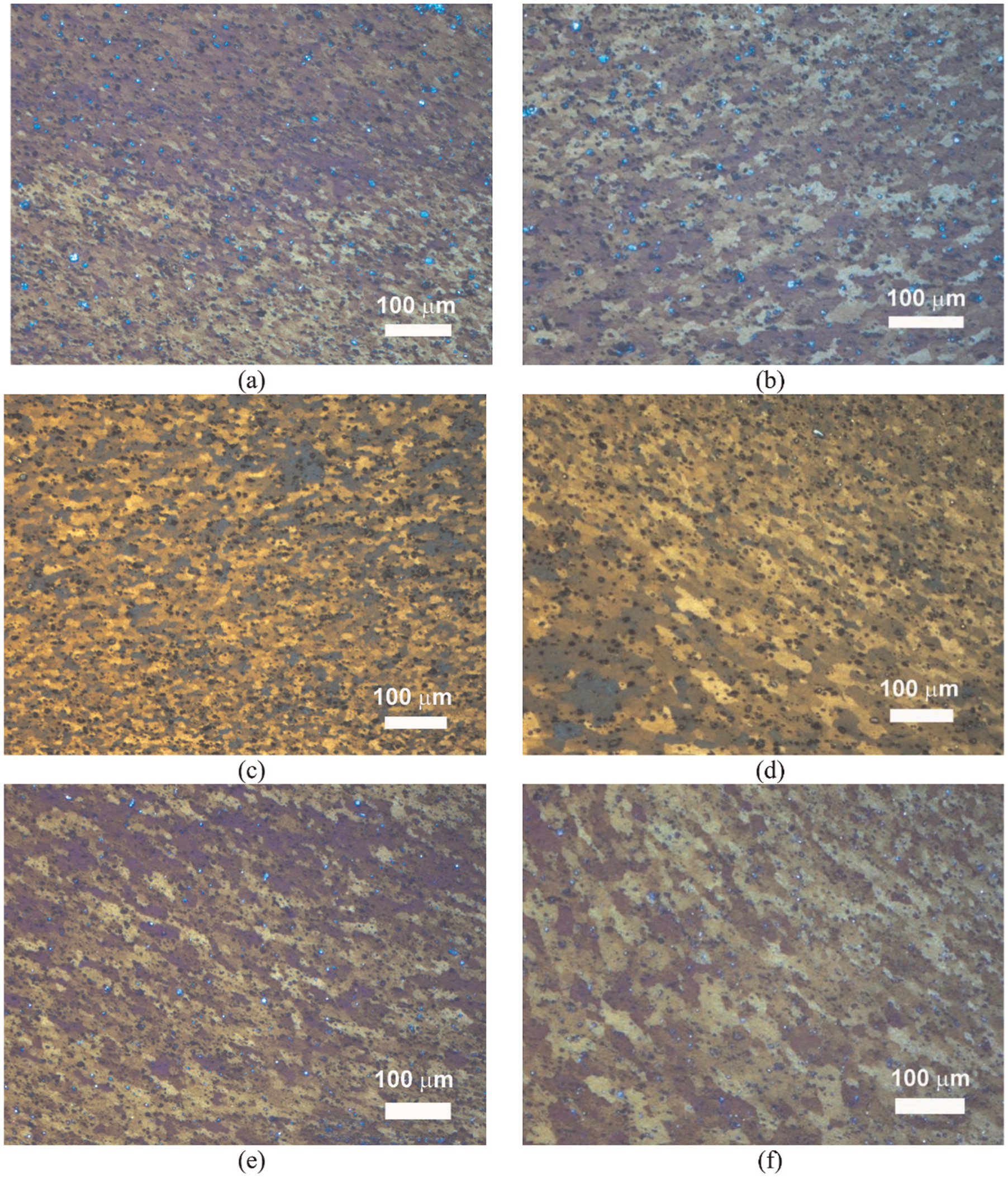
Microstructure in the different zones of the welded joints obtained under different process methodology: (a) SZ and (b) TMAZ of conventional FSWed joint (pin configuration); (c) SZ and (d) TMAZ of DS-FSWed joints obtained using pin–pin configuration; and (e) SZ and (f) TMAZ of DS-FSWed joints obtained using pin–pinless configuration (ω = 1200 r/min; v = 100 mm/min, AS–AS positioning).
Table 3 reports the mean grain size as a function of welding methodology and tool configuration, measured at different zones of the welded joints. The considerably small grain size in the SZ, combined with the equiaxed grain shape, implies the occurrence of dynamic recrystallisation because of the very high levels of deformation and temperature reached in such zone during FSW. 28 Furthermore, there is no evidence for melt in the SZ. As far as the conventional FSW process is concerned, the mean grain size near the surface in contact with the shoulder during welding is slightly larger than the one in the opposite surface; on the contrary, the DS-FSWed joints show a more uniform grain size in the SZ, irrespective of the tool configuration used. In the TMAZ, both in conventional- and in DS-FSWed joints, a uniform grain size is observed both in the AS and RS. Although the TMAZ experienced a significant plastic deformation, following an upward flowing pattern around the SZ, dynamic recrystallisation did not occur due to an insufficient deformation level.
Mean grain size of base alloy and welded joints as a function of welding methodology and tool configuration, measured at different zones of the welded joints (ω = 1200 r/min and v = 100 mm/min, AS–AS sheet positioning).
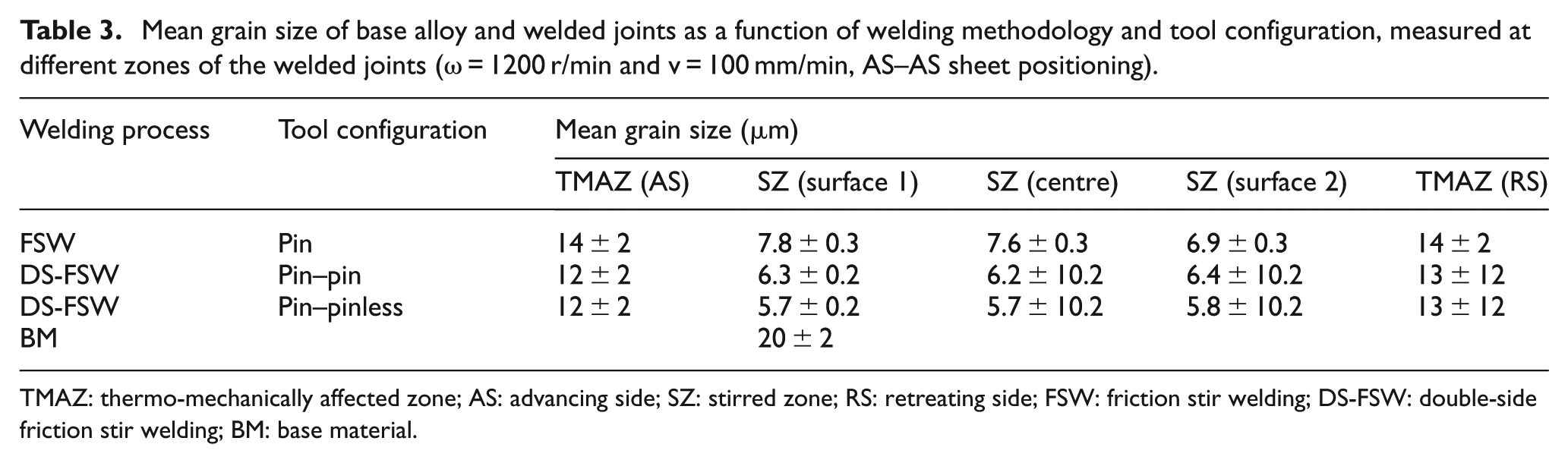
TMAZ: thermo-mechanically affected zone; AS: advancing side; SZ: stirred zone; RS: retreating side; FSW: friction stir welding; DS-FSW: double-side friction stir welding; BM: base material.
Such results are confirmed by the nanoindentation tests, described by Cabibbo et al., 17 which showed hardness and local Young’s modulus values across the DS-FSWed joints more uniform than those obtained in conventional FSW.
Post-welding formability
In comparison with conventional fusion welding techniques, one of the most important advantages offered by FSW is the relatively high post-welding formability exhibited by the welded blanks, which makes the process very attractive in the manufacturing of TWBs. To this purpose, formability was investigated both on conventional FSWed joints and DS-FSWed ones, obtained under the same process conditions chosen in the microstructural analysis.
The LDH value represents the punch stroke at the peak of the load versus stroke curves (Figure 6), namely, the dome height of the deformed samples at the onset of necking. According to the ductility results, obtained by tensile tests (Figure 3), the LDH values of the welded joints, irrespective of the welding methodology used, are lower than those obtained on the BM; such results denote that the presence of the welding line determines a reduction in formability.14–19,21,25,27
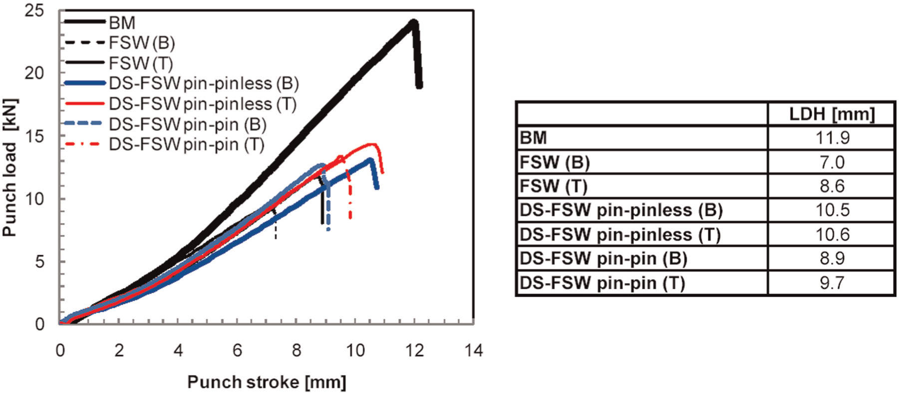
Punch force versus punch stroke curves obtained by hemispherical punch tests for BM and welded joints as a function of the different testing conditions.
As far as the conventional FSW process is taken into account, the B arrangement leads to a LDH value lower than the T one (Figure 6). In order to understand such discrepancy, the manufacturing method of the welded joints has been taken into account. As a matter of fact, the pin tool was designed with a small clearance between its bottom surface and the backing plate in order to avoid their contact. This involves the formation of a small geometric discontinuity into the joint, located at the bottom surface of the weld (‘surface 2’), which acts as a notch (Figure 7(a)). As far as the B arrangement is concerned, the local increase in the intensity of the stress field, caused by the notch, leads the FSWed sample to fail at the geometric discontinuity (Figure 7(a)). In the T arrangement, obtained by positioning the FSWed blank with the notch in contact with the punch, since the notch is subjected to a biaxial tensile stress state less severe than that in the B arrangement, the failure of the deformed joint occurs at the step produced by the sinking action applied by the shoulder (Figure 7(b)).
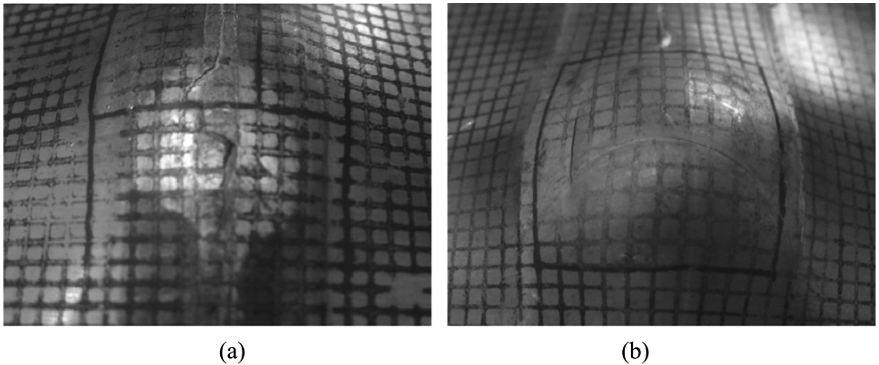
Conventional FSWed joints subjected to the hemispherical punch test: (a) B arrangement and (b) T arrangement.
By focusing the attention on the DS-FSW, the joints are characterised by LDH values higher than those measured on the conventional FSWed joints; such improvement can be attributed to the beneficial effect of the second pass that allows both the closure of the geometric discontinuity and the reduction in the height of the step produced by the first pass. Furthermore, by comparing the DS-FSW to the conventional FSW, it can be seen that the former is characterised by more uniform recrystallised grains across the SZ than the latter (Figure 5). Finally, the joints obtained using the pin–pinless tool configuration lead to LDH values higher than those given by the pin–pin one, irrespective of the sheets’ arrangement. It clearly appears that in the pin–pinless configuration, the LDH value, that is almost independent of the sheet arrangement, is only about 12% lower than that of the BM, while in the pin–pin tool configuration, the LDH reaches values of about 19% and 25% lower than that of BM in the T and B arrangements, respectively (Figure 6).
A more accurate evaluation of formability is obtained by means of the forming limit curves (FLCs), defined by plotting the major strain versus minor strain experimental data (Figure 8). As expected, in agreement with the results shown by Kim et al. 19 on FSWed 6111-T4 sheet and by Kinsey et al. 29 on AA5182-H00 aluminium alloy, the formability of the base alloy is always higher than that of the welded joints. In the stretching side of the FLD, according to the behaviour exhibited by the LDH (Figure 6), it appears that for a given minor strain, the major strain measured on the DS-FSWed joints is systematically higher than that provided by the conventional FSWed ones. The higher vertical position of the FLCs, provided by the DS-FSWed samples, confirms that formability is strongly improved by performing the DS-FSW. In the drawing side of the FLD, as shown by tension test (Figure 3), such discrepancy decreases and the FLCs tend to overlap.
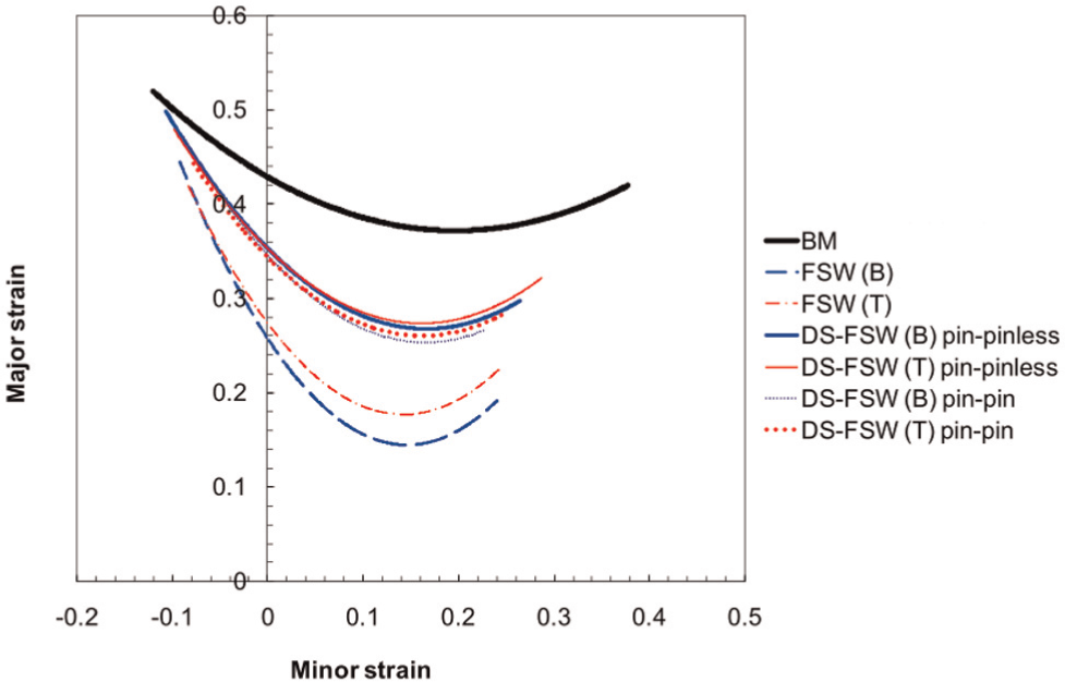
Influence of welding process and sample arrangement of welded joints versus base material on forming limit curves.
The comparison among the different FLCs obtained in the DS-FSW, using both the pin–pinless and the pin–pin configurations, shows that the FLCs are scarcely affected by the tool configuration used in the second pass; however, the DS-FSW in the pin–pinless configuration leads to higher major strain values. Finally, the B arrangement is characterised by the lowest major strain values, according to the LDH results shown in Figure 6. Such discrepancy tends to be negligible in the DS-FSWed joints.
It is noteworthy to observe that the process methodology and sample arrangement also affect the extension of the FLCs. In particular, Figure 8 shows that the FLCs obtained with the welded joints have an extension smaller than the one obtained on the BM. Such behaviour is almost negligible in the drawing zone of the FLD, according to the tensile results shown in Figure 3; it becomes instead significant in the stretching region, as confirmed by LDH values in Figure 6.
In conclusion, by putting together the results obtained in this work and those shown by the authors in Cabibbo et al., 17 it can be assumed that the better formability of the DS-FSWed joints with respect to the conventional FSWed ones can be attributed as follows: (1) to the more homogeneous recrystallised grained structure across the SZ, from top to bottom of the sheet section, (2) to the local elastic modulus uniformity (i.e. reduced Young’s modulus) across the weld, (3) to the similar elastic response to the BM and (4) to the less marked hardness variation in the DS-FSWed welds as compared to the conventional FSWed ones.
Conclusion
In this work, the DS-FSW on AA6082 sheets was widely investigated. The effect of the tool configuration, positioning of sheets with respect to the welding tool and welding parameters on the mechanical properties, microstructure and post-welding formability of joints was analysed and discussed in detail. In order to evaluate the effect of the process methodology, the experimental results obtained using the DS-FSW were compared with those given by the conventional FSW.
The results can be summarised as follows:
The conventional FSWed joints show ultimate tensile strength and elongation higher than those exhibited by the DS-FSWed joints.
The mechanical behaviour of the DS-FSWed joints strongly improves as welding is performed using the pin–pinless configuration, with ductility levels similar to the ones exhibited by the conventional FSWed samples. The worst tensile results are obtained as the ‘pinless’ tool is used to perform both welding passes.
The tensile responses of the joints are slightly affected by the rotational speed and welding speed.
The SZ undergoes dynamic recrystallisation, with grains finer than those of the base alloy, because of the very high levels of deformation and temperature reached during welding. Furthermore, the DS-FSWed joints exhibit finer and more uniform grains than those shown by conventional FSWed ones.
In the TMAZ, irrespective of the welding methodology, dynamic recrystallisation does not occur due to the insufficient deformation level.
The DS-FSWed joints are characterised by LDH values higher than those measured on the conventional FSWed ones. Furthermore, the DS-FSWed joints, obtained using the pin–pinless tool configuration, lead to the obtaining of LDH values higher than those given using the pin–pin tool.
The FLCs obtained on the DS-FSWed joints are systematically higher than those provided by the conventional FSWed ones. Furthermore, the FLCs obtained on the DS-FSWed joints are scarcely affected by the tool configuration used, even though the pin–pinless configuration leads to higher values of major strain.
The joint formability is significantly affected by the weld arrangement with respect the punch.
The better formability of the DS-FSWed joints with respect to the conventional FSWed ones can be attributed to the more homogeneous recrystallised grained structure, the local elastic modulus uniformity across the weld, the similar elastic response to the BM and the less dramatic hardness variation in the DS-FSWed welds.
Footnotes
Acknowledgements
The authors wish to thank Dr Massimiliano Pieralisi and Mr Daniele Ciccarelli for their help in carrying out the experimental work.
Declaration of conflicting interests
The authors declare that there is no conflict of interest.
Funding
This research received no specific grant from any funding agency in the public, commercial, or not-for-profit sectors.