
Abstract
This study investigates a new automatic motion planning algorithm for industrial robots performing a pick-and-place task in an obstacle-free workspace. The new technique finds an optimal trajectory for a parallel kinematic manipulator. The centre sphere method and multi-objective optimisation are used to solve this problem. To obtain an optimal path, an objective function that includes a hypothetical jerk fitness value, a path length function and a virtual obstacle avoidance function is defined, and the path planning problem is solved using particle swarm optimisation. For greater efficiency, the planning problem is modified to include physical constraints on the robot. The method is tested on a 4-degree-of-freedom parallel kinematic manipulator through simulations, where the optimum virtual sphere radius is obtained. Experiments are performed with an actual parallel kinematic manipulator, and a comparison of the performance of the robot executing the same tasks with trajectories obtained using the new method and two existing methods is made. The results show the efficiency and the effectiveness of the proposed approach in determining the optimal trajectory for a 4-degree-of-freedom parallel kinematic manipulator in an obstacle-free workspace.
Introduction
Motion planning is a fundamental problem for industrial robots and is crucial to ensuring good performance in robots, particularly for high-speed tasks such as pick-and-place with a parallel kinematic manipulator (PKM). This problem has been posed as a nonlinear optimal control problem (NOCP), 1 but these problems are very difficult to solve because of the highly nonlinear dynamics and obstacle avoidance constraints. There may be multiple paths, and the algorithm must select one according to certain criteria such as the shortest path, the minimum energy or some dynamic performance index. 2 Finding a planning method for a PKM that is dynamic, time-optimal and includes physical constraints is of significant concern in robot motion planning.
Related work in automatic motion planning
Automatic motion planning has been the focus of intensive research in recent years. Consequently, there is an increasing demand for advanced programming and control technologies. 3 Many industries use offline programming within a manually controlled and specified work environment. This is true in the automotive industry, particularly with regard to high-speed assembly and component handling.
Over the last few decades, much attention has been given to the problems of motion planning and control, which are often posed as an NOCP. Both direct and indirect methods can be used to solve an NOCP. 4 Most techniques in the literature for solving the motion planning problem solve the NOCP using direct methods. Unlike indirect methods, which require deriving the necessary conditions for optimality, direct methods convert the NOCP into a parameter optimisation problem. The most common optimality criteria are based on energy, time, torque or jerk. Optimal trajectory tracking exploits the fact that the motion along a predefined path can be described by a set of parameters, and the optimal velocity profile that satisfies the optimality criteria is found using algorithms such as dynamic programming (DP) or sequential quadratic programming (SQP). 5
Many types of objective functions have been proposed to optimise trajectories. One example is a function with a term proportional to the total execution time and another term proportional to the integral of the squared jerk along the trajectory.6,7 Another approach involves formulating the path planning problem as the constrained minimisation of a functional representing the total joint movement over the complete path. 8 The paths are optimised with respect to a specified cost function, 9 and terms are added to ensure a smooth transition between segments.
The vast majority of articles discussing trajectory planning for a PKM do not or only briefly mention selecting paths that avoid obstacles. For example, in Huang et al., 10 a modified algorithm for finding a time-optimal path that includes jerk limits for a 2-degree-of-freedom (DOF) translational parallel robot performing rapid pick-and-place tasks is discussed. In Guangfeng et al., 11 the authors presented a method for trajectory planning of an end effector in Cartesian space. Using modified sine functions and the inverse kinematics in joint space at key points, feasible trajectories were generated for a Delta robot.
With the development of artificial intelligence and numerical techniques, heuristic algorithms have been used widely and effectively to solve optimisation problems. 12 In Zacharia et al., 13 a modified genetic algorithm (GA) and the ‘bump surface’ concept were used to find the optimal solution that accounts for multiple solutions of the robot inverse kinematics and the required intermediate configurations
A method for industrial robot trajectory planning using an evolutionary algorithm was presented in Cecil and Marthaler. 14 In Dehghani and Fattah, 15 the Hamiltonian function was formed and the necessary conditions for optimality were derived using Pontryagin’s minimum principle. Although this approach has been used successfully in many applications, it has not been as popular in recent years. The primary reasons are that the convergence domain is relatively small and it is difficult to incorporate inequality terms in the path constraints.
Stochastic optimisation methods have been used by many authors to solve motion planning problems.16,17 In Lahijanian et al., 18 the motion of the robot was modelled as a Markov decision process (MDP), and the motion specifications were transformed into a probabilistic computation tree logic (PCTL) problem. However, similarly to Rapidly-exploring Random Trees (RRT), RRT is difficult to apply in problems involving systems with complicated dynamics or that are under-actuated because it requires the design of a two domain-specific extension heuristics: a distance metric and node extension method.
Most of the approaches to motion planning find paths that are either collision-free or minimum-time, that is, problems with either space or time constraints. 19 Unlike the previous research, the main purpose of this study is to seek the optimum trajectory, which is related to the optimal path and the optimal time in pick-and-place tasks. The main goal is to construct an automatic motion planner suited to a 4-DOF PKM performing pick-and-place tasks. Section ‘Main contribution’ describes the contributions of this work, and section ‘Outline’ gives a brief outline of the article.
Main contribution
The overall contribution is the development of a method to find the optimal trajectory for robots. The more specific technical contributions of this study are the following:
An approach for obtaining the optimal trajectory for a PKM under the specified conditions;
The addition of a hypothetical jerk fitness value to the multi-objective optimisation algorithm for optimal motion planning;
The introduction of the centre sphere method for automatic motion planning in an obstacle-free environment.
Outline
The remainder of the article is organised as follows. The automatic motion planner is described in section ‘Automatic motion planner’, which first provides the problem statement for the pick-and-place task (section ‘Problem statement’) and then presents an overview of the proposed solution to the problem (section ‘Overview of the solution’). Section ‘Models’ presents a mathematical model of the 4-DOF PKM and the task. The proposed optimisation algorithm is presented in section ‘Formulation of the optimisation problem’, section ‘Automatic motion planning with the centre sphere method’ demonstrates and discusses the centre sphere method, section ‘Experimental verification’ verifies the efficiency of the proposed algorithm through multiple examples and conclusions are presented in section ‘Conclusion’.
Automatic motion planner
Problem statement
The application domain considered in this work is picking up and placing objects in a structured industrial environment. Figure 1 shows examples of pick-and-place tasks performed by humans in everyday life. It can be observed that the path of the object is approximately an arc with a small curvature. This task is very easy for most humans, but finding an algorithm to plan a trajectory between the initial and final destinations is not as simple and presents an interesting challenge.
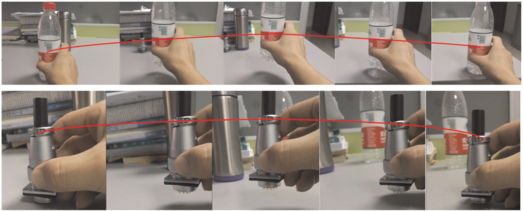
Two examples of humans performing a pick-and-place task: water bottle (top row) and connector (bottom row).
In this study, it is assumed that the workpiece is in the robot workspace, the pick-and-place region is inside the robot workspace and all trajectories begin and end at rest. With the problem defined, the following subsection will give an overview of the solution.
Overview of the solution
Figure 2 presents an overview of the problem-solving process for a robot performing a pick-and-place task. The process is divided into path optimisation and time optimisation. The automatic motion planning system is designed as an online planner that will plan a trajectory from the initial position to the final position within an obstacle-free environment. All motions are expected to start from the specified initial position of the workpiece and end at the specified final position.
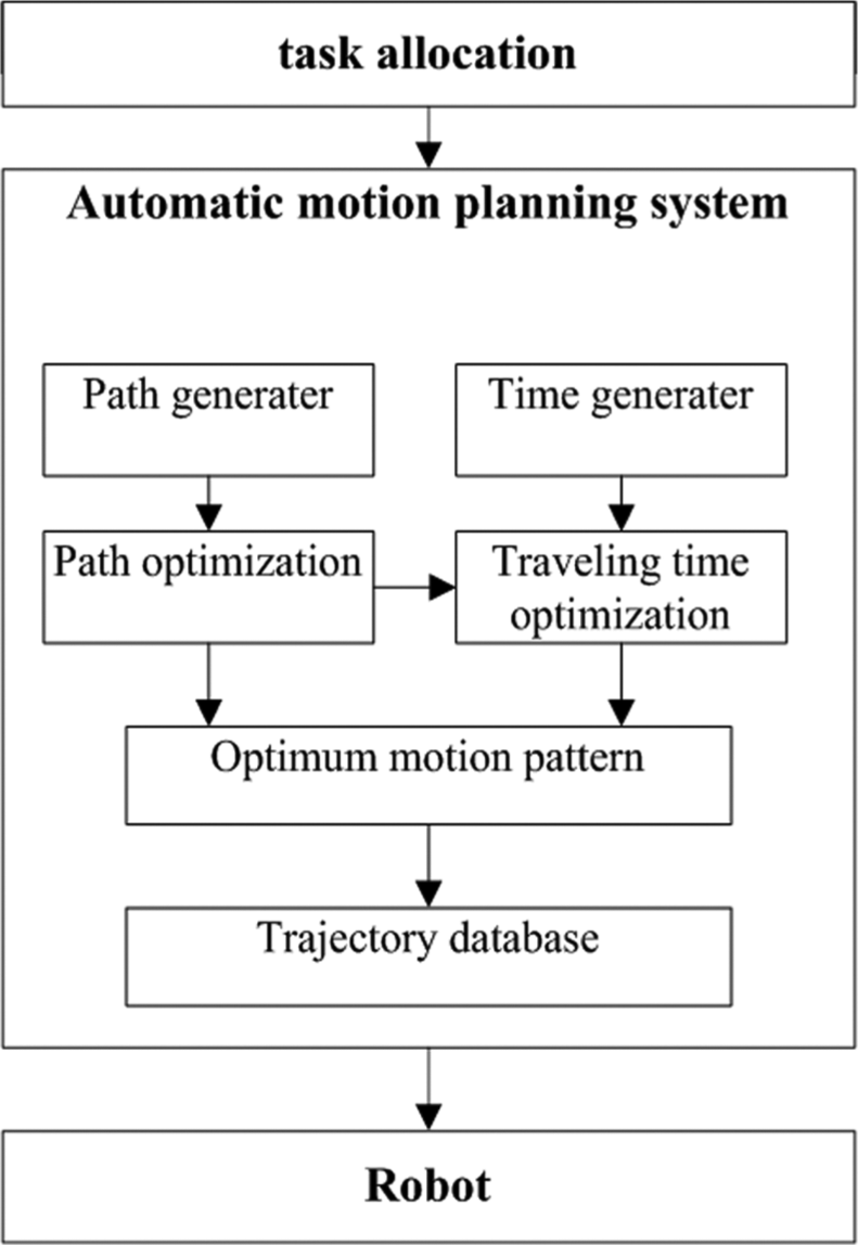
Overall process of the motion planner.
In engineering practice, finding the globally optimal trajectory is a very complex problem. To achieve flexible automation, a motion planning algorithm that generates a sub-optimal or near-optimal trajectory based on certain performance indexes is designed. The proposed algorithm contains three parts. The first step in the motion planning algorithm is to generate a path randomly with a path generator and then to determine the best sequence of points visited by the end effector with a path optimisation module. This module, which is called only once, assures that the path is optimal in some sense. The second step is to choose the best time parameter. This step is performed by the time optimisation module, which assures that the time parameter satisfies the dynamics constraints. Finally, a trajectory database module generates the optimal trajectory that will guide the robot in the pick-and-place task. In the next section, mathematical models of the robotics dynamics and the trajectory, which are essential for the proposed algorithm, are developed.
Models
The 4-DOF PKM
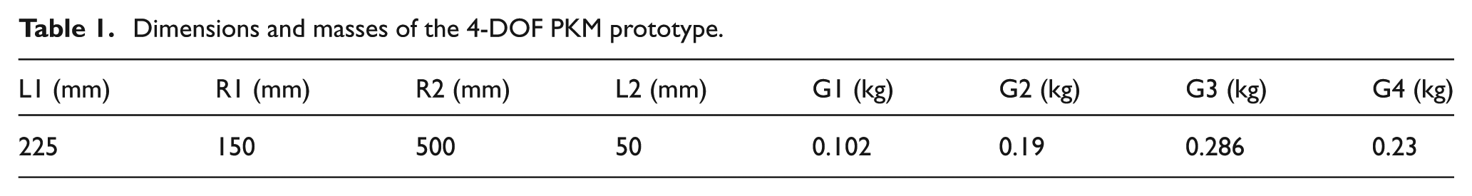
The Delta robot is a spatial parallel manipulator that performs purely translation motion. 20 It is well known for its high speed. As shown in Figure 3(a), rotational DOF was added by attaching universal joints to the transmission shaft. This creates a 4-DOF PKM capable of high-speed translation and rotation. Dimensions and masses for the 4-DOF PKM, which is now in use in a watch factory (see Figure 3(c)), are listed in Table 1. This PKM can perform arrangement and handling operations in an industrial production line. Generally, the workspace of the 4-DOF PKM is complicated. To simplify the computations, a cylindrical volume is assumed for the workspace, as shown in Figure 4.
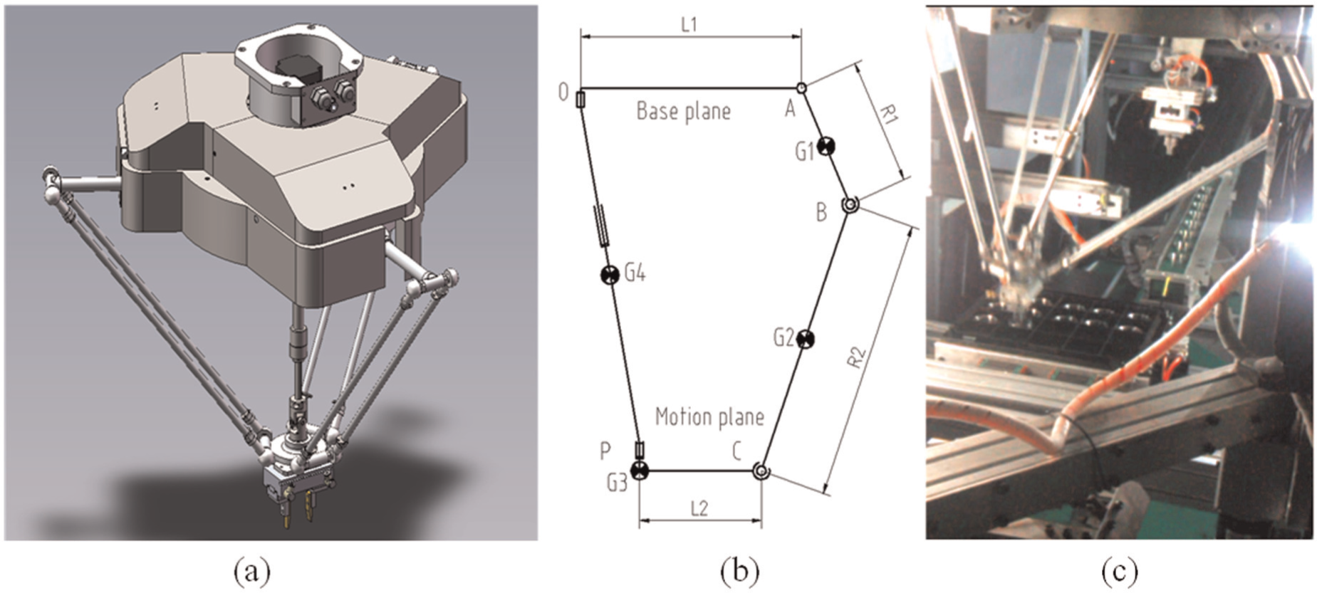
The 4-DOF PKM: (a) illustration of the prototype, (b) diagram of the open kinematic chain and (c) the 4-DOF PKM in operation.
Dimensions and masses of the 4-DOF PKM prototype.
Pick-and-place task.
Rigid-body dynamics
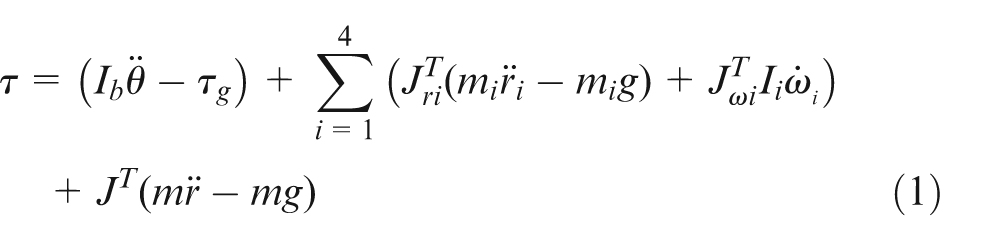
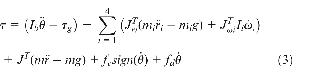
A model of the dynamics of the 4-DOF PKM is essential for solving the motion planning problem with a time-optimal trajectory. As shown in Figure 3(b), the lumped mass method is used to simplify the model. The masses and the dimensions are listed in Table 1. Using the method of virtual work, the rigid-body dynamic model of the 4-DOF PKM can be formulated in terms of the link Jacobian matrices and the virtual power. 20 The generalised actuator force vector can be expressed as (the definitions of the matrices and the vectors in equation (1) are given in Appendix 1)
The energy dissipation is taken into account by applying the model presented by Van Willigenburg and Loop, 21 in which both the friction (Coulomb) and the linear viscous damping are considered together in the dissipation force
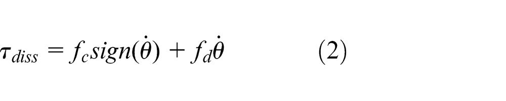
In equation (2),
where
Obstacle model
The pick-and-place task is depicted in Figure 4. The problem includes the path and an obstacle. In our method, obstacles are represented as virtual objects. This approach is important for the optimisation formulation described below. First, we assume that there are two points in space that bound the path in the robot workspace. Because of their high degree of smoothness and ease of implementation, we use quintic B-splines, which are fifth-order polynomials,
22
to construct the path. In this study, the position of the robot is described in Cartesian space with space and time parameters. For the 4-DOF PKM, there are 4 DOFs in Cartesian space, three translational degrees and one rotational degree, so if the path planning requires
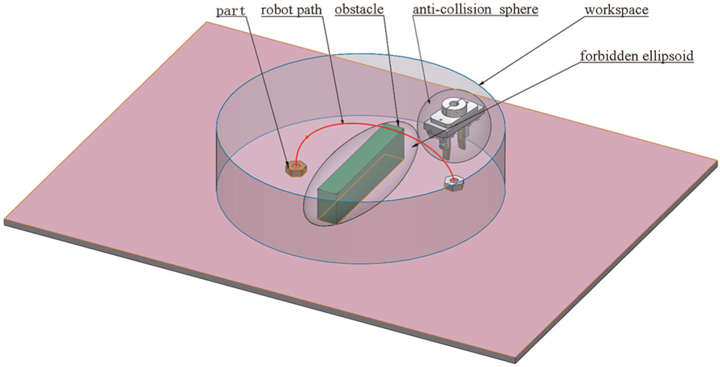
There are no obstacles in the workspace in the pick-and-place task. However, the robot manipulator is required to lift the workpiece off the work surface to avoid friction, that is, dragging the workpiece along the work surface. Therefore, it is essential that additional constraints be included. A virtual obstacle can be applied with an appropriate mathematical model. Perumaal and Jawahar 23 proposed a ‘safe ellipsoid’ technique for the selection of waypoints in generating a feasible trajectory. The safe ellipsoid is tangent to the corners of the obstacle and encloses the obstacle as shown in Figure 4. The safe ellipsoid must be expanded to a certain size because of the geometrical characteristics of the PKM gripper, which is represented as a sphere. The pick-and-place task is illustrated in Figure 4, which shows the obstacle, the PKM gripper, the workpiece, the workspace and the robot path.
Let A, B and C be the semi-axes of the circumscribing ellipsoid depicted in Figure 4. The trajectory points must be located outside the ellipsoid according to the following equation 24
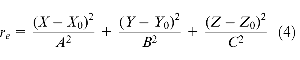
where
For a path
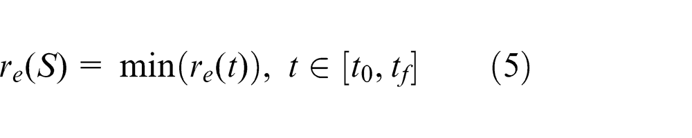
We define the following penalty function
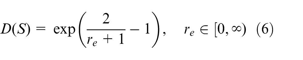
Using equations (4)–(6), the virtual obstacle avoidance problem is converted into an optimisation problem. The penalty function (6) will be one component of the multi-objective optimisation function developed in the next section.
Formulation of the optimisation problem
In the previous section, we detailed the model and the constraints of motion planning. In this section, we introduce the terminology, the notation and the general formulation of the nonlinear optimisation problem. The proposed optimisation technique is divided into two parts. First, an optimal path for the robot is generated according to an optimality criterion, that is, based on the minimisation of the path objective function. Second, temporal information is generated for the selected geometric path based on the minimisation of a time objective function. Any kinematic constraints and dynamical constraints, which are expressed in terms of upper bounds on the velocity, the acceleration and the forces, are taken into account in the minimisation of the time objective function.
Hypothetical jerk fitness and overall objective function
As explained in the previous section, virtual obstacles are avoided with equation (6). The path length can be chosen for minimum energy, which is included in the formulation of the optimisation problem. In addition to virtual obstacle avoidance and path length optimisation, limiting the value of the jerk is important. A smooth trajectory reduces the likelihood of exciting the structural resonance modes of the manipulator. Limiting the value of the jerk (the derivative of the acceleration) is an indirect way to bound the rate of the joint torques and yields several positive effects such as reducing the stresses on the actuators and the robot structure.
There are several algorithms in which the jerk appears in the objective function. For instance, Verscheure et al. 5 minimised the integral of the squared jerk, whereas Zanotto et al. 25 used a minimax approach to minimise the maximum value of the jerk along the trajectory. However, these techniques assumed that the total time was known (defined a priori). Moreover, it is not possible to impose kinematic constraints on the trajectory with these methods. The jerk function presented in this study is used only for generating a smooth path and the time parameter is artificial, so this jerk function is called the hypothetical jerk fitness function.
The objective function in the proposed technique is the sum of three terms having related effects:
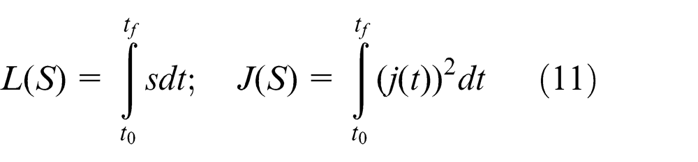
The first term is proportional to the path length function.
The second term is proportional to the virtual obstacle avoidance function.
The third term is proportional to the hypothetical jerk fitness function.
Of course, reducing the value of the first term will shorten the path length, reducing the value of the second term will reduce the clearance from the virtual obstacle and reducing the value of the third term will cause the path to be more smooth. The trade-off among the three objectives can be performed by suitably adjusting the weights of the three terms.
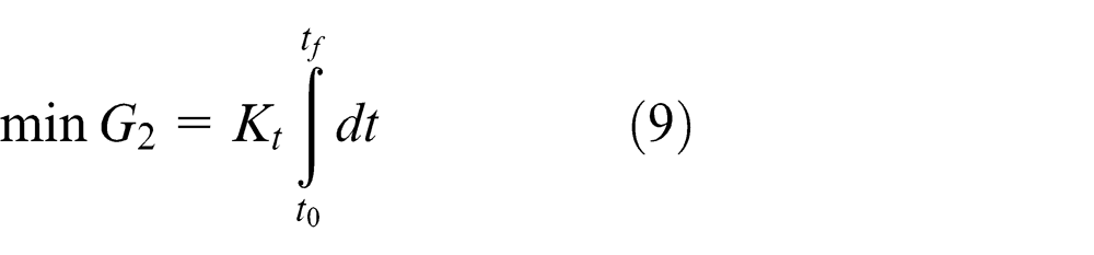
The time objective function is simply the total travel time. Reducing the value of the time objective function will not only increase the speed of robot but also increase vibration and the power requirements of the robot. Hence, the optimal trajectory planning problem can be formulated as
subject to
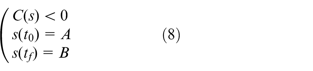
and
subject to
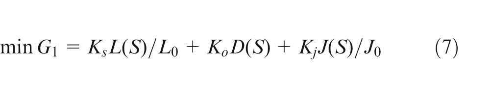
where
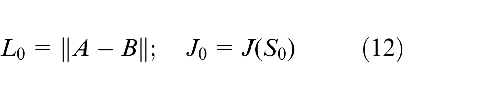
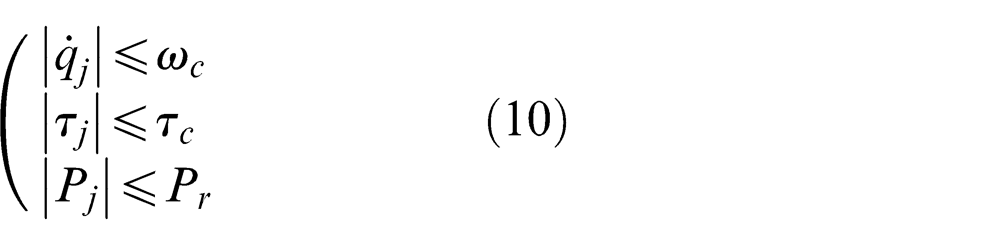
and D(S) is given by equation (6). The cost function G 1 was written in a form that allows the user to weight the relative importance of the path length, obstacle avoidance and jerk. Smooth motions are obtained by choosing appropriate weighting factors. The definitions of the other symbols appearing in equations (7)–(12) are given in Appendix 1. By solving the optimisation problem in equation (7), the optimal path between the two end points can be obtained. By solving the optimisation problem in equation (9), the optimal time, which maximises the throughput rate, is computed. The trajectory obtained by solving this optimisation problem satisfies conditions (8) and (10).
Time-optimal planning and scheduling problem statement
The automatic motion planning algorithm described in the previous sections was implemented by solving the minimisation problem formulated in section ‘Hypothetical jerk fitness and overall objective function’ using dedicated software, which was written in C++ and executed as a normal priority process on an Intel Pentium D 2.6 GHz processor in the Microsoft Windows XP operating system.
The optimisation strategy is hierarchical. The steps of the algorithm can be summarised as follows:
A random initial path in the workspace is generated, and particle swarm optimisation (PSO)26–28 is applied to optimise the path.
PSO is used to solve the optimisation problem in equations (7)–(12) to obtain a sequence of control points in the task space.
A suitable initial time parameter is chosen, and the optimisation problem in equations (9) and (10) is solved iteratively.
The values of the kinematic constraints and the dynamic constraints depend on the structural constraints and the drive power constraints of the robot. The solution of the optimisation problem is obtained using PSO and an iterative technique.
The total automatic motion planning algorithm is divided into two parts. First, path planning is accomplished using PSO. Second, the time-optimal trajectory is generated with the iterative method. A flowchart of the proposed algorithm is given in Figure 5.
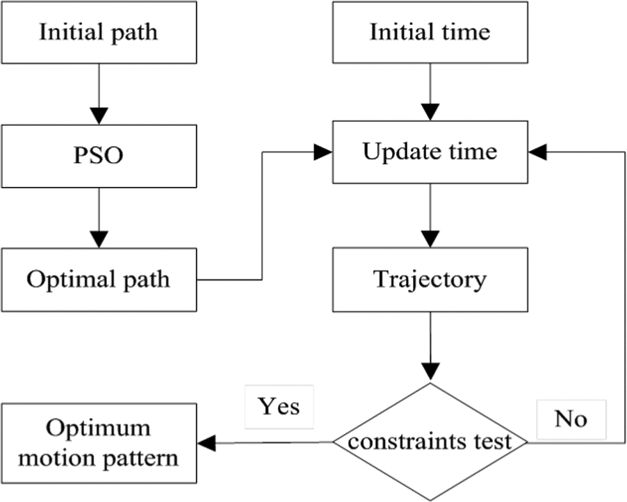
Flowchart of the proposed algorithm.
Automatic motion planning with the centre sphere method
Based on the previously described optimisation process, the centre sphere method is introduced. Because there are no obstacles within the workspace in the pick-and-place task, the robot manipulator simply has to lift the workpiece to a certain height above the workbench to avoid friction. Therefore, a sphere is introduced as a virtual obstacle to ensure that the robot remains a certain distance from the workbench. This method is called the centre sphere method. In expressions (4)–(6), the centre of the sphere is assumed to lie in the middle of a straight line joining the start and end points. In this situation A = B = C = R, where R is the radius of the sphere, and different values of R may lead to different optimisation results. Simulations were conducted with various values of R to find the best value.
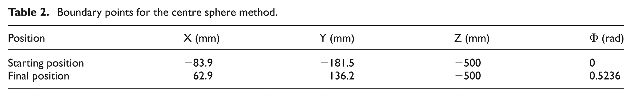
Simulations were implemented in the MATLAB (R2012a) programming environment and executed on a personal computer with a 2.6 GHz CPU and 3.41 GB of memory with the Microsoft Windows operating system. The simulations were conducted using the values of the initial position (Ps) and the final position (Pe) given in Table 2. The dimensional data for the 4-DOF PKM are listed in Table 1.
Boundary points for the centre sphere method.
The following values were used for the weights in the objective function:
Table 3 lists the travel times for the pick-and-place task with various values of the sphere radius. The minimum travel time of 0.24 s was achieved in cases 18 and 19, but case 1 produced the minimum jerk. The computation time was relatively long at approximately 4 s. Approximately 85% of the planning time was spent on computing the time parameter, which depends on the dynamics; hence, the computation time was relatively long.
Simulation results with various values of R.
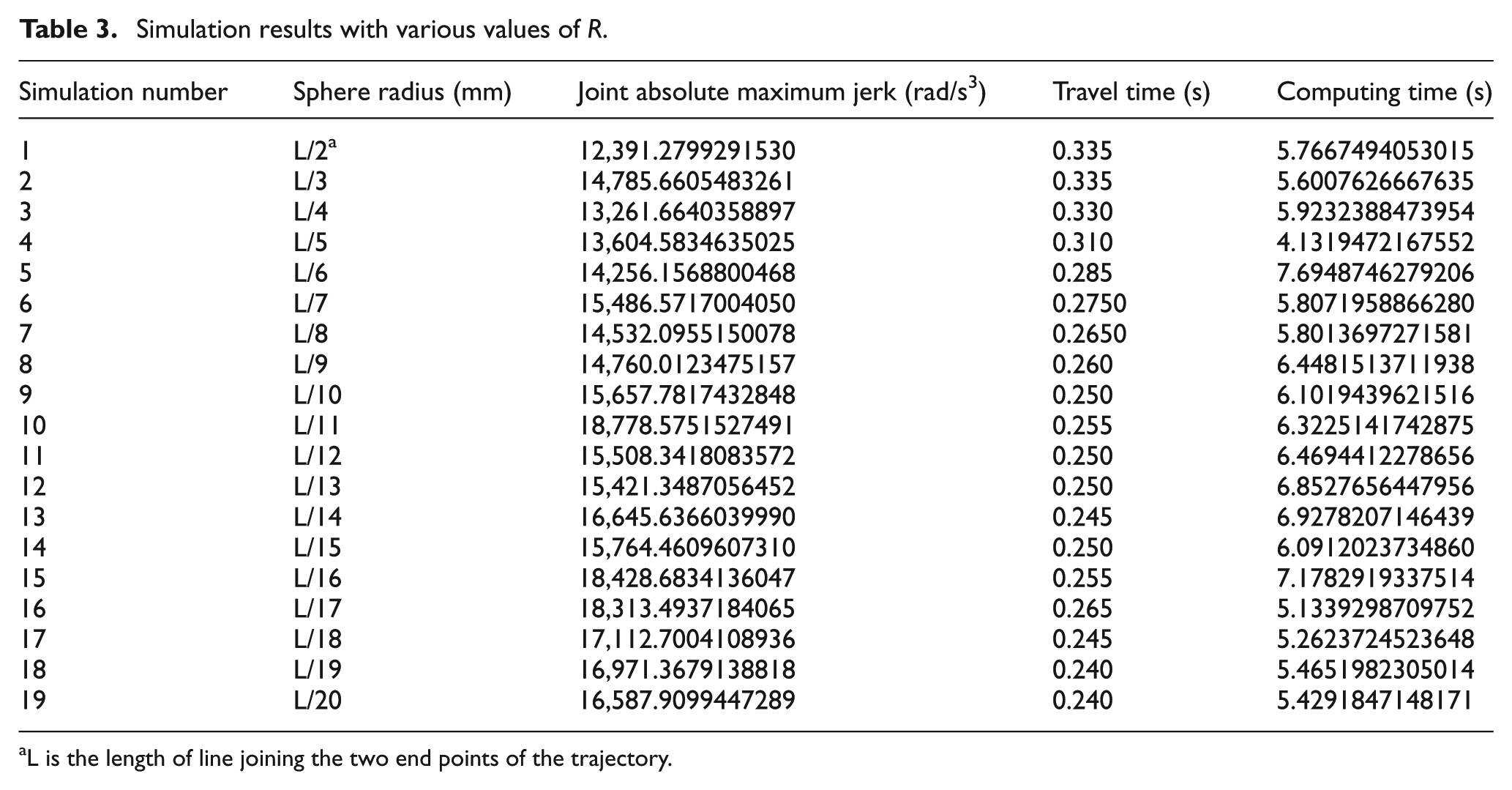
L is the length of line joining the two end points of the trajectory.
From Figure 6, it can be observed that the results for case 11 are superior to the others. Furthermore, if we compare the travel times of the 19 cases, we note that case 19 is very efficient compared to the other cases. Case 11 produced the best overall trade-off between travel time and maximum jerk in the optimisation.
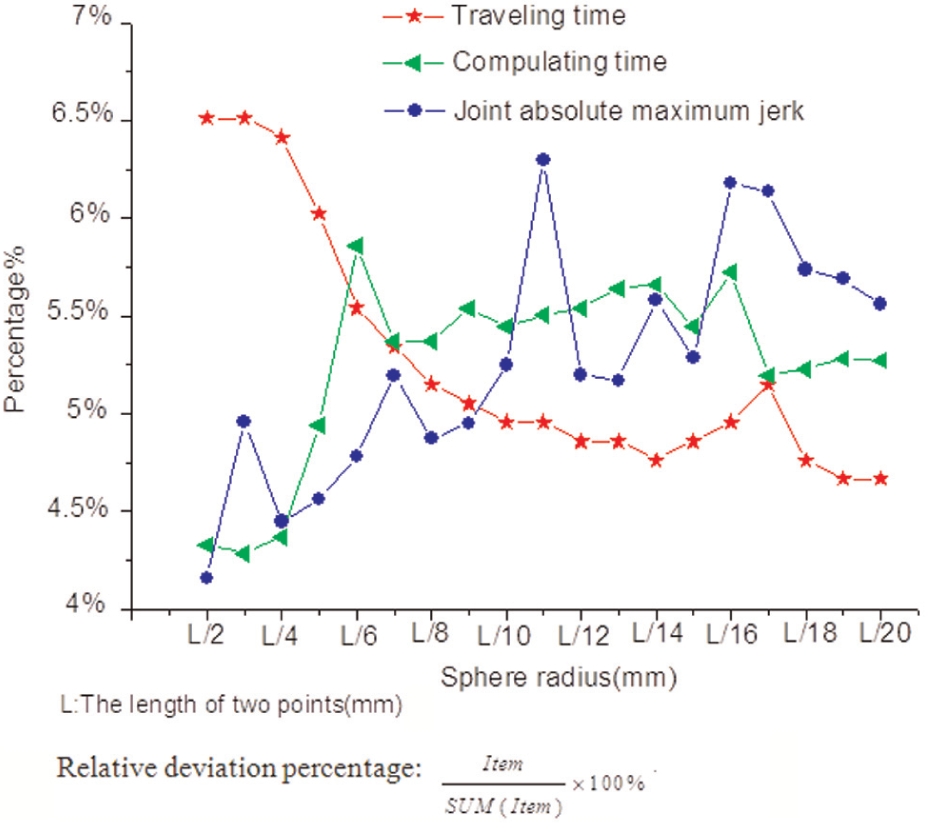
Percentages of the three terms for various virtual sphere radii.
For case 11, the radius of the virtual sphere was one-twelfth of the handling distance. The three-dimensional (3D) path for this case is shown in Figure 7, where it can be observed that the path is very smooth. The results show the effectiveness of the algorithm in finding trajectories that flow smoothly and flexibly between the two end points in performing the pick-and-place task in an obstacle-free space. These characteristics are very important for a high-speed PKM. In addition, the results show that with the centre sphere method, a sphere radius of one-twelfth of the handling distance is optimal.
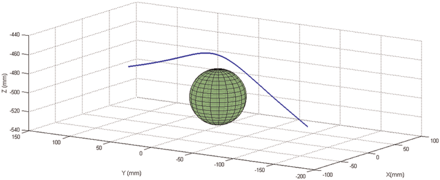
The path in three-dimensional workspace.
Experimental verification
In this section, the proposed algorithm is implemented with an actual 4-DOF PKM. In the experiments, the 4-DOF PKM performed pick-and-place tasks in an obstacle-free environment with several trajectories. The experimental set-up for the 4-DOF PKM is shown in Figure 8. Specifically, the robot control system is composed of the upper and lower computer modules, which are produced by the Huazhong Numerical Control Co. Ltd. (HNC), with the upper computer used to send instructions to the lower computer. The lower computer converts the data into the actual pulse signals that are sent to alternating current (AC) servo system (Mitsubishi) so that the robot manipulator can perform the desired end-effector task.
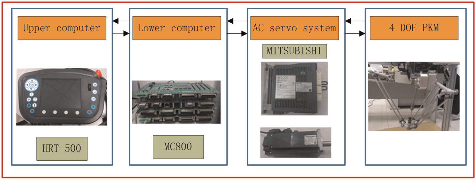
Experimental set-up.
To verify the effectiveness of the proposed centre sphere method, the robot performed the same task with three different paths. The first path is the one obtained from the optimisation algorithm. The second path has a half-ellipse shape, which can be defined using three points: the start, the end and a transition point. As proposed in Nabat et al., 29 the equation of an ellipse can be approximated using the projection of the curvilinear abscissa of a circle on the ellipse. The third path is known as the adept motion path and is used for commercial pick-and-place robots. This comparison permits us to evaluate the performance of a robot for a pick-and-place task. Plots of the height versus the length of the three paths are shown in Figure 9. For comparison, a fifth-order polynomial time law was used as the universal motion law for the three paths. The performance measure was the time required for the robot to complete a single trip.
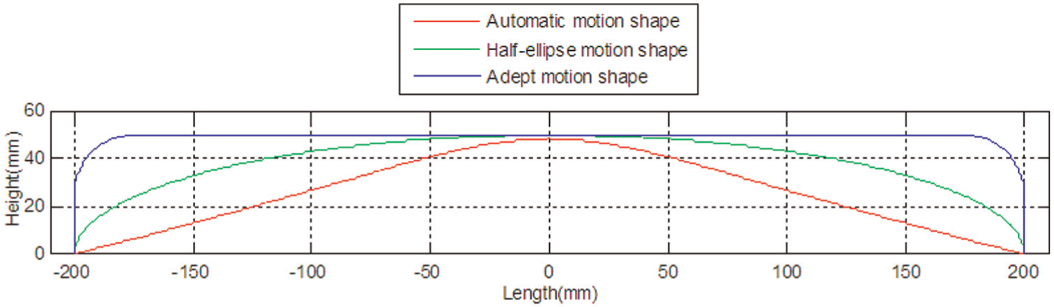
The three test paths in the workspace.
The results in the previous section showed that the automatic motion planning method based on the centre sphere method is effective, flexible and superior for robot motion planning. In this section, the proposed centre sphere method is implemented on an actual 4-DOF PKM to further verify its practicality and effectiveness.
To ensure that the experiment could be conducted safely and successfully, we first performed simulations using parameter values (e.g. the lengths of the links) equal to those of the actual robot, as shown in Table 1. The simulation results for the three paths are shown in Figures 10 and 11.
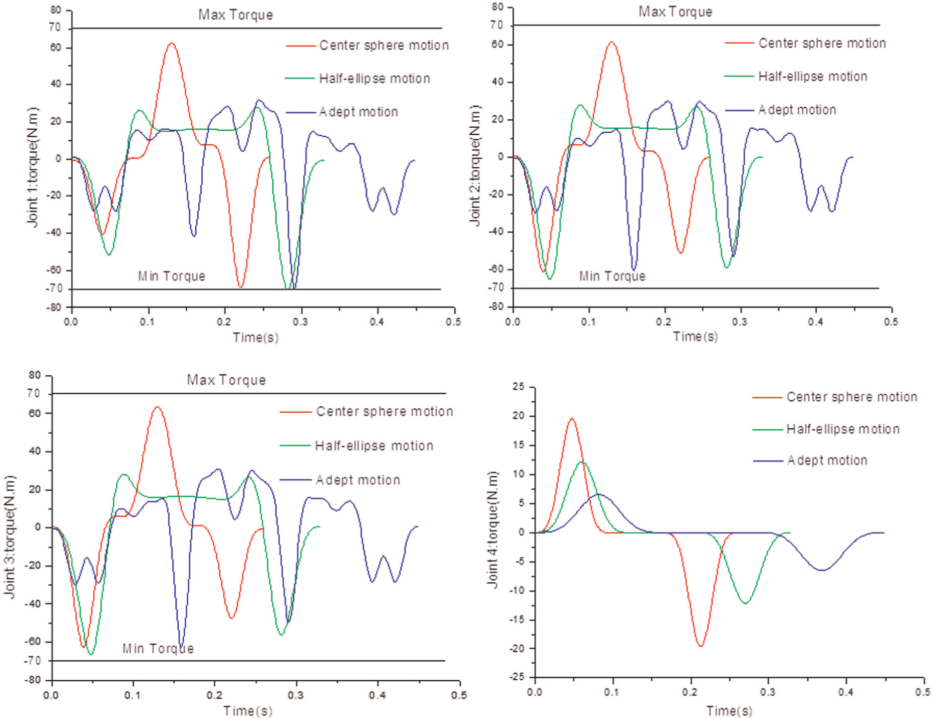
Joint torque time histories for the three paths.
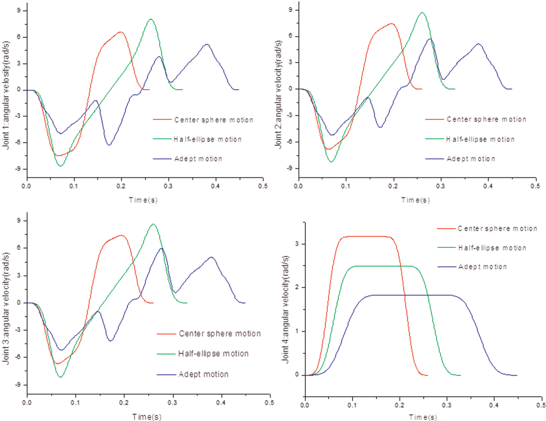
Joint velocity time histories for the three paths.
It can be observed in Figure 10 that in each case, the torques have oscillations, but the absolute maximum values of the torques are all confined to a specific range (−70 to 70 N m). Moreover, the adept motion path exhibits more oscillations than the other paths. From the results, we can observe that the minimum travel time parameter is mainly governed by the torque constraint in joint 1.
The joint velocities for the three cases are shown in Figure 11. We can observe that the optimised profile is not only smooth but also the obtained trajectories are stable in start and end stages. With regard to the time parameter and the path shapes, it can be observed that half-ellipse path is more similar to the optimised path, and the adept motion path has the worst performance, which confirms the time optimality of the optimised path compared to the half-ellipse path and the adept motion path in satisfying the dynamics constraints.
To compare the path generated by the centre sphere method and the other two methods, we defined 100 pick-and-place tasks. A task starts in the pick position and moves to the place position and back to pick position. The same tasks were performed using paths generated with the three methods, the optimisation algorithm, the half-ellipse method and the adept motion method, to plan the trajectories between the end points Ps and Pe listed in Table 4 for the 100 cases.
Boundary points for the centre sphere method.
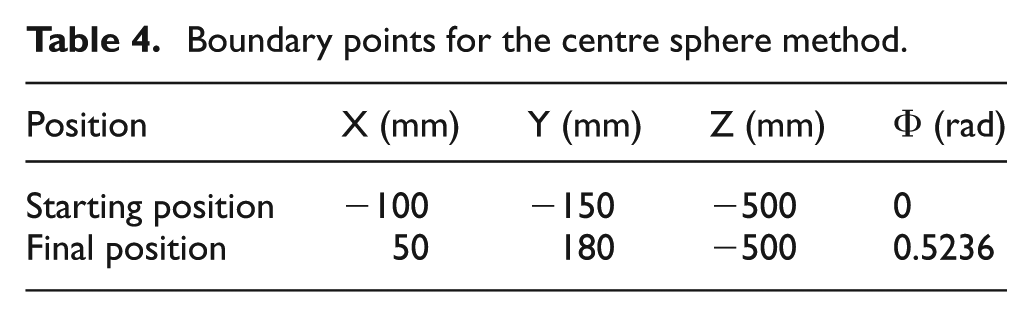
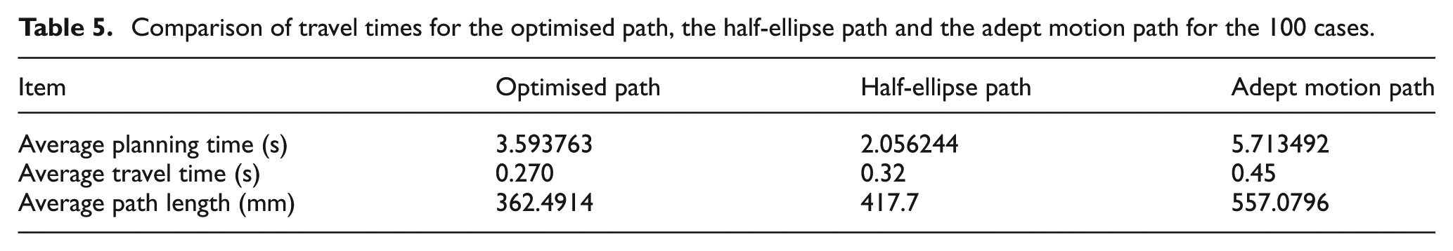
Table 5 shows the averages of the experimental results. It can be concluded that the average travel time of the optimised paths is less than those of the other two types of paths, but the average planning time for the half-ellipse paths is the least. It can also be observed that the optimised paths are shorter on average than the others. Summarising Table 6, the automatic motion shape and half-ellipse motion shape have the optimum motion time than adept motion shape.
Comparison of travel times for the optimised path, the half-ellipse path and the adept motion path for the 100 cases.
Boundary test points.
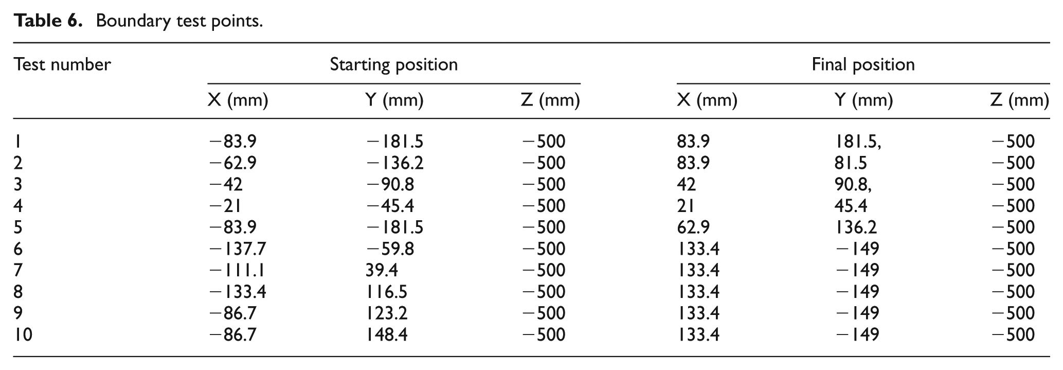
To compare the execution times of the half-ellipse paths and the optimised paths, we chose 10 cases, for which the start and end positions are listed in Table 6. These cases were used to define 10 complete pick-and-place tasks. Because the same start and end positions are used, an exact comparison of the two methods can be made.
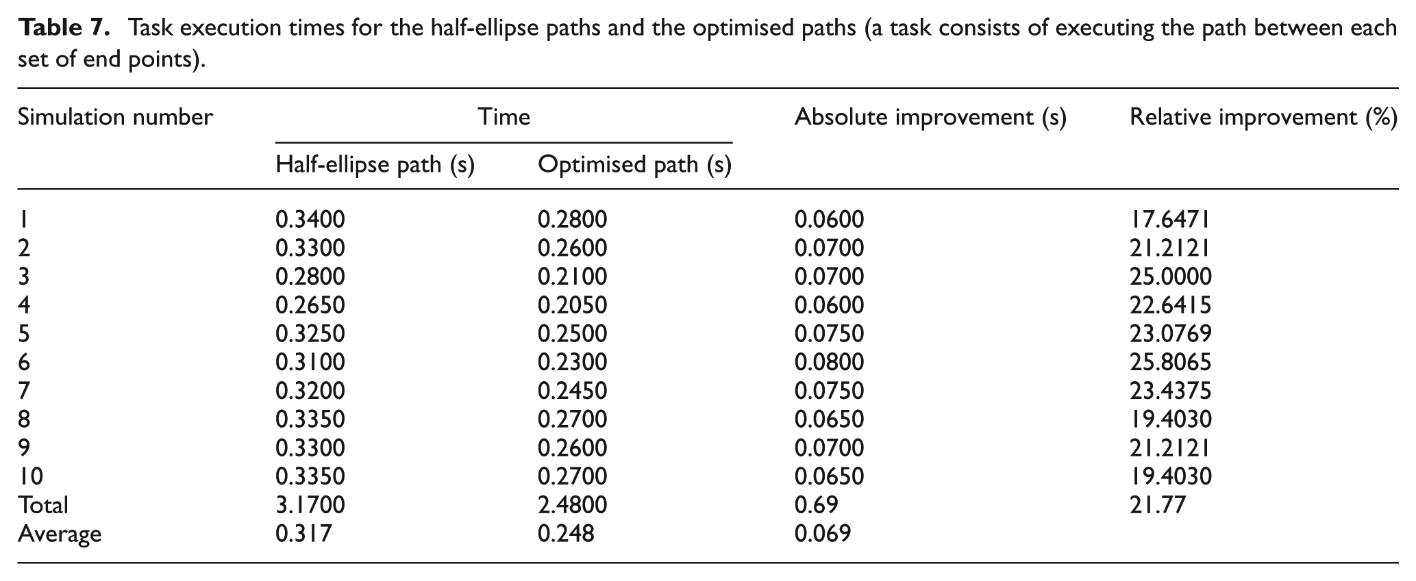
The experimental results are shown in Table 7. It should be mentioned that the path execution times do not include the time required for planning. The planning time is not included because the planning could be performed while the robot is moving towards the next target or while the object is being picked up or placed. The average travel time for the optimised paths was approximately 0.248 s, which was 0.069 s less than the average for the half-ellipse paths, an improvement of 21.77%. These results show that the proposed algorithm yields better performance than the half-ellipse method for motion planning.
Task execution times for the half-ellipse paths and the optimised paths (a task consists of executing the path between each set of end points).
From Figure 12, we can observe that the proposed algorithm converges after 40 iterations, which is sufficiently fast that it can be used in practice.
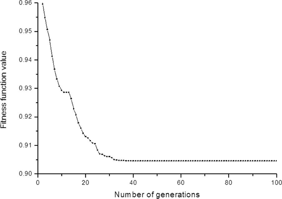
Convergence of the proposed algorithm.
Conclusion
A multi-objective optimisation was used to plan robot motion for an obstacle-free pick-and-place task. A virtual centre sphere was introduced to ensure that the path was realistic, that is, to prevent the robot from dragging the workpiece over the work surface. As part of the centre sphere method, the time-optimal problem was solved with an iterative method with respect to the dynamics constraints. The proposed method has the following characteristics: (1) the optimal virtual sphere radius is one-twelfth of the handling distance, which can be adapted for producing smooth paths with the centre sphere method. (2) The method enables the computation of the time-optimal trajectory, which can be quickly adapted for a given task and thereby provide an immediate response with a near-optimal solution. (3) The experimental results show that the correlation between the path shape and the trajectory has a significant effect on the time required for executing the path. The average travel time for the optimised paths was approximately 0.248 s, 0.069 s less than the average for the half-ellipse paths, a relative improvement of 21.77%. These results show the advantage of the proposed algorithm over the half-ellipse method. (4) Because the motion planner was developed specifically to provide optimal paths with short computation times and feasible trajectories for a 4-DOF PKM, the proposed method can also be applied to other PKMs.
Future work will focus on improving the discrete trajectory by adding other objective functions such as a robot structural life function. In addition, increasing the computational efficiency and the robustness of the proposed method is a goal in future research. Options for increasing the computation speed include an implementation using multiple-core CPUs or a graphics processing unit (GPU).
Footnotes
Appendix 1
Appendix 2
Acknowledgements
The authors would like to thank the editor for his important contribution to this work. The authors would also like to thank the anonymous reviewers for their very useful comments.
Declaration of conflicting interests
The authors declare that there is no conflict of interest.
Funding
This work was supported, in part, by the Major Project of National Science and Technology (Grant No. 2012ZX04001012) and the Wuhan Science and Technology Research Project (Grant No. 2013010501010120).