
Abstract
Designers often have some difficulties in fulfilling complex product design due to the lack of design resources. It is a crucial issue that how to help designers to produce design from enormous, isomeric, and even distributed design resources of virtual prototyping and then ally those correlative distributed design resources to collaborative design. This article is devoted to an object-oriented design resource management for virtual prototyping in collaborative design. After the design resource unit model is proposed with the representation model of virtual prototyping, the object-oriented product design resource representation framework for virtual prototyping is then put forward. The storage, usage, search, version management, and security management strategies for design resources of virtual prototyping are then discussed in detail. The framework of design resource management system for virtual prototyping is also put forward to support collaborative design. The collaborative design of cold heading machine is given as an example, which demonstrates that the methodology is helpful to distributed knowledge reuse for collaborative design.
Introduction
Virtual prototyping 1 might accelerate the product design process and reduce product cost through integrating design and analysis process to realize design optimization, 2 workspace analysis and simulation, 3 reconfigurable manufacturing system, 4 structural design and analysis, 5 and so on. It is generally acknowledged that virtual prototyping involves all kinds of product design resources, even in the distributed design entities. The design process of complex products is always so complicated that the design efficiency should be improved by design resource management in collaborative design. Thus, it becomes a key issue to realize effective product design with design resource management for virtual prototyping in collaborative design, and the corresponding collaborative design system as well.
The current research on information management for virtual prototyping in product collaborative design can be mainly classified into two types: one focuses on the research on design object and the other is collaborative design method.
The first one focused on the design object includes two aspects: product structure information model of design objects and product information management model of design objects.
Product information model of design object
Li et al. 6 proposed object-oriented product structure model. Janardanan et al. 7 put forward a collaborative product structure management model for assembly modeling. Aleksi et al. 8 presented object-oriented modeling of product configuration, parameters, and topologies in mass production of custom. Han and Do 9 introduced an object-oriented conceptual model for collaborative product development. He et al. 10 proposed product knowledge modeling in design. Chandrasegaran et al. 11 summarized the knowledge representation in product design systems.
Product information management model of design object
Gorla and Liu 12 proposed an object-oriented database FHIN. Wong et al. 13 put forward an object database server for collaborative virtual environment. Pullan et al. 14 applied an object-oriented modeling in collaborative design. Barbosa et al. 15 presented a collaborative design environment with design history, CAD data model, and virtual prototyping. Chungoora et al. 16 proposed ontology-based knowledge management. Xue et al. 17 proposed object-oriented design database 18 representations and introduced an evolutionary design database model to describe design requirements and design results at different design stages. Yi et al. 19 put forward a collaborative mechanism for distributed product design. Whitfield et al. 20 proposed an approach for managing the exchange of engineering product data. Becattini et al. 21 discussed computer-aided inventive problem analysis algorithm.
Another kind of research focuses on collaborative design method. For instance, Mahdjoub et al. 22 discussed a collaborative product innovation framework via product life cycle management. Hong and Park 23 put forward a collaborative design process on the Axiomatic Design Theory. Rodriguez and Al-Ashaab 24 brought forward a design knowledge management system supporting collaborative product development. Kim et al. 25 proposed a collaborative product commerce framework for sharing product information across enterprises. Sun et al. 26 proposed version merging for CAD files to resolve the version management. Zhou et al. 27 developed an Internet-based product design platform to integrate traditional CAD platform and distributed product structural knowledge based on STEP. Whitfield et al. 28 put forward a collaborative platform for integrating and analysis requests. Srinivasan 29 proposed an integration framework for product life cycle management. The collaborative conceptual design based on distributed knowledge resource was discussed in detail in our research. 30
However, design resource management for virtual prototyping is one of the bottlenecks for complex product design. On the one hand, it is so difficult to transfer distributed design resources into product design efficiently. The current product design resource management always focused on relational database management systems. In these systems, as the design resources and their types are relatively independent, the structure and description type of design resource items cannot be changed after they were set, which might cause that the dynamic management of the design object cannot be realized. On the other hand, integration of distributed multi-disciplinary design resources for virtual prototyping in collaborative design is also absent. It is a crucial issue that how to ally those correlative, enormous, isomeric, and even distributed design resources for virtual prototyping to collaborative design.
This article proposes an object-oriented design resource management model for virtual prototyping in product collaborative design. The remainder of this article is organized as follows. Section “Object-oriented product design resource management” proposes object-oriented product design resource management. In section “Storage and usage modes of design resource for virtual prototyping,” the storage and usage modes of product design resource for virtual prototyping are discussed. The framework of object-oriented design resource management system for virtual prototyping in collaborative design is developed in section “Framework of object-oriented design resource management system for virtual prototyping in collaborative design.” In section “Application,” the design of a cold heading machine is given as an example, which demonstrates that the methodology is helpful to manage distributed design resources for collaborative design. Section “Conclusion” concludes this article.
Object-oriented product design resource management
Virtual prototyping representation model
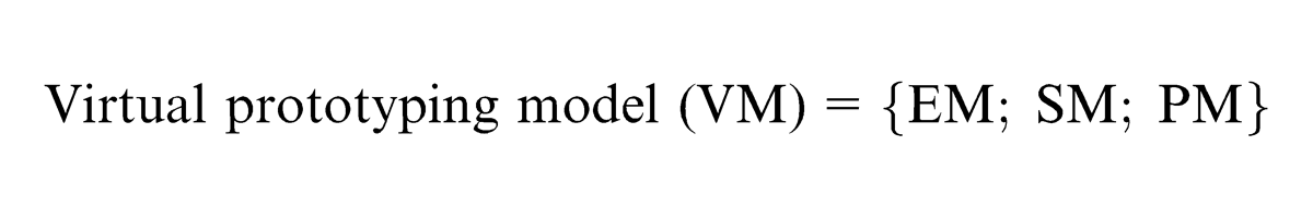
With the virtual prototyping technique, the designers build virtual models of mechanical systems involving the characteristics of physical product, such as appearance, spatial relationship and kinematics, and dynamic information. The application of the virtual prototyping technique is a process that the function, appearance, and other aspects of products meet the requirements through building, simulating, and improving the models. According to this process, the design resource model for virtual prototyping can be classified into three basic types: entity model (EM), state model (SM), and process model (PM), as shown in the following
EM
It is a product model established by designers according to the design task, including all the components of a product, such as mechanical three-dimensional (3D) model, mechanical two-dimensional (2D) model, control model, hydraulic model, and electronic wiring layout diagram. This model is the foundation for composing the virtual prototyping of a product, which reflects the constraint relation between the basic structure of the product and the geometric information of each structure.
For instance, the manipulator in a cold heading machine, created by UG NX, a 3D modeling software, is a mechanical 3D EM. It is a virtual assembly model, which reflects the basic components and the constraint relationship between each component. Other related simulation analyses, such as structural analysis, kinematics analysis, and dynamic analysis, are achieved on the basis of this EM. The drawing of manipulator in a cold heading machine, created by UG NX, is a mechanical 2D EM, which demonstrates the relationship and structure of each component.
SM
It is the physical model which has been imposed some external state constraints, such as models under the ultimate load state in the finite element analysis, models under the ultimate work position in the kinematics simulation, and models under ultimate motion state. VM is in a certain state by adding constraints. For example, when using ANSYS, a finite element analysis software, to analyze the VM, the ultimate load SM can be obtained by adding force loads and displacement constraints. The maximum load SM of the manipulator is obtained by using ANSYS on the basis of the mechanical 3D EM; when using ADAMS, a multibody dynamics software, to achieve the simulation of kinematics and dynamics, the ultimate motion SM and the ultimate work position SM can be obtained by adding constraints.
PM
It is the accumulation of the SMs, which is the result of the continuous expression of the adjacent SM, including all the SMs from the initial state to the end state, such as the motion PM in kinematics simulation, the stress variation model in statics analysis, and the control program in motion control. For instance, with the SM of two ultimate work positions of the manipulator, its motion PM can be obtained by connecting all work position SMs from the nearest work position to the farthest work position.
The relationships among the above three models are shown in Figure 1. The EM is the foundation of others, the SM is obtained by adding static constraints on the EM, and the PM is obtained by the constant accumulation of the SM. Accordingly, the PM can be regarded as the set of all models between initial SM added with initial constraints on the EM and the ultimate SM added with ultimate constraints on the EM. The PM can also be obtained by adding dynamic constraints on the basis of the EM, where the dynamic constraint is a regular constraint from the initial constraint to the ultimate constraint. From the analyses mentioned above, each PM can be decomposed into several continuous SMs. The SM and the PM always appear in the process of simulation; thus, the EM can be optimized based on the feedback of the related contents among these models. For example, the limited load analysis of the statics simulation model on the SM and the motion range of the movement model on the PM are the guides of relevant structure optimization to the EM.
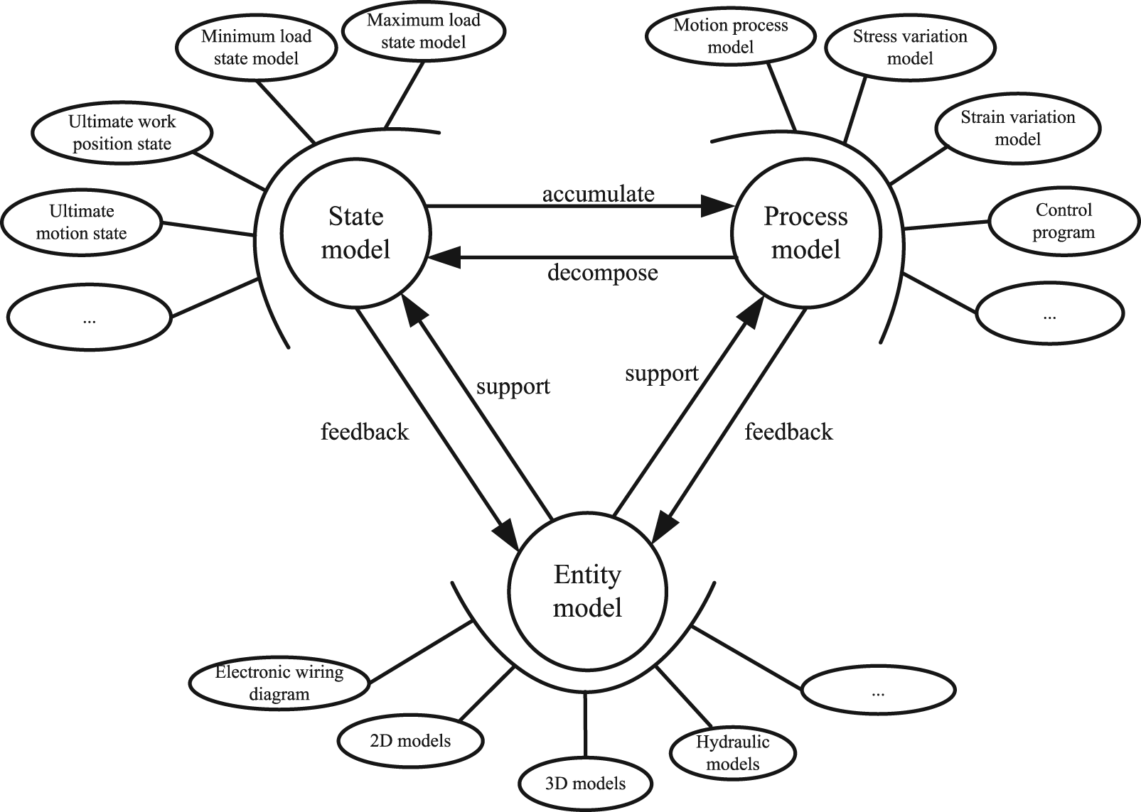
Virtual prototyping representation model.
As shown in Figure 1, each model contains several sub-models with different properties, such as the EM can be divided into mechanical 2D model, mechanical 3D model, hydraulic model, and electronic wiring diagram according to different entity properties. There are some correlations and mutual constraints among different EMs; for instance, the mechanical 2D model and mechanical 3D model are restricted with each other by dimension and location information. The SM is divided into ultimate motion SM, ultimate work position SM, ultimate load SM, and so on. The PM is classified into the motion PM, load variation PM, dynamics simulation PM, control program PM, and so on.
The relationships of each virtual prototyping resource model of the manipulator in a cold heading machine are illustrated as an example as shown in Figure 2. It contains a UG NX 3D model, an ANSYS analysis model, and an ADAMS simulation model.
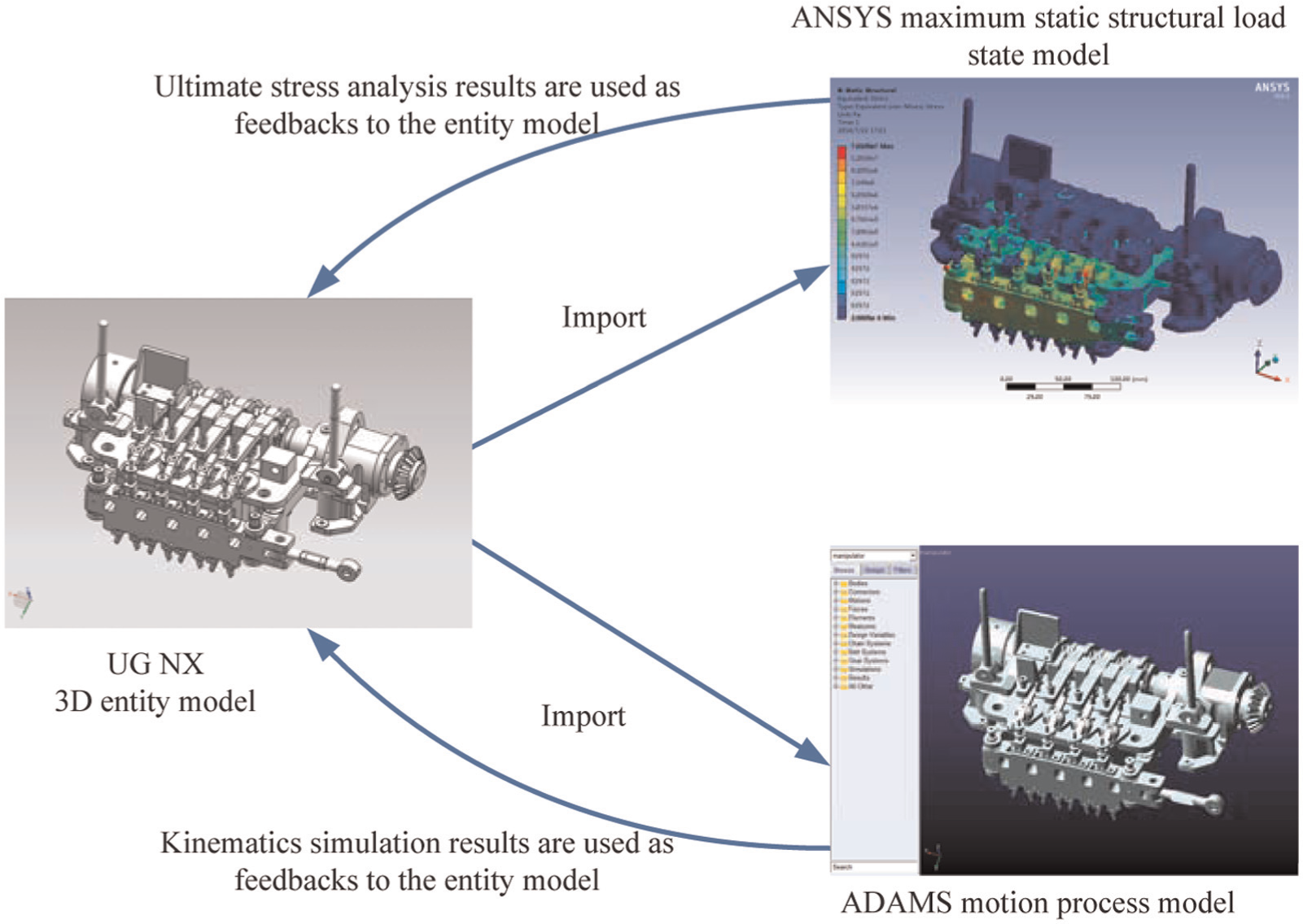
The example of three models of manipulator in cold heading machine.
The 3D model of the manipulator is an EM. Based on this EM, the Parasolid model exported from UG NX can be imported into ANSYS to achieve the analysis of ultimate load state. Meanwhile, the motion PM can be obtained by importing x_t model into ADAMS to complete kinematics analysis. The results of the ultimate load SM and the motion PM can be used as feedbacks to the EM, which can be regarded as a guide for the mechanical structure of the EM.
Design resource unit model for virtual prototyping
The virtual prototyping–based design resource unit (VRU) consists of three related elements: object (O), property (P), and value (V). The expression is as follows

Figure 3 is the representation structure of VRUs, in which the structure in the dotted line frame is a VRU. As shown in Figure 3, the object mainly refers to the information of design objects to support virtual prototyping, that is, principle drawing, Printed Circuit Board (PCB) drawing, mechanical drawing, and others at different levels; the property is the corresponding property that belongs to the object; the value is the corresponding value of the object property at the specific level of virtual prototyping.
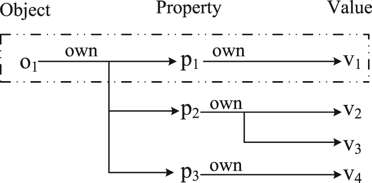
Virtual prototyping–based design resource unit model.
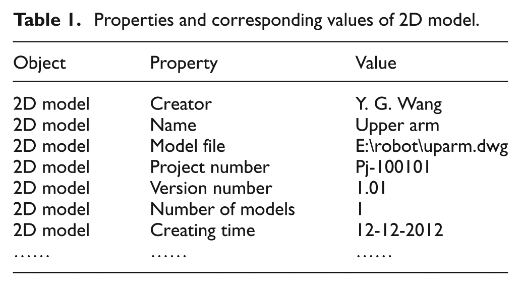
For instance, Figure 4 is the 2D assembling model of the manipulator in a cold heading machine, with a series of attribute information summarized in Table 1 with characteristic attributes of the 2D model, such as project number, model name, and model version. For a specific model, the values of the attributes are different from others. Thus, it is convenient to distinguish from other similar models according to the common attributes of the 2D model, such as creator, number of model, and model file. For a specific model, the values of common attributes can be the same.
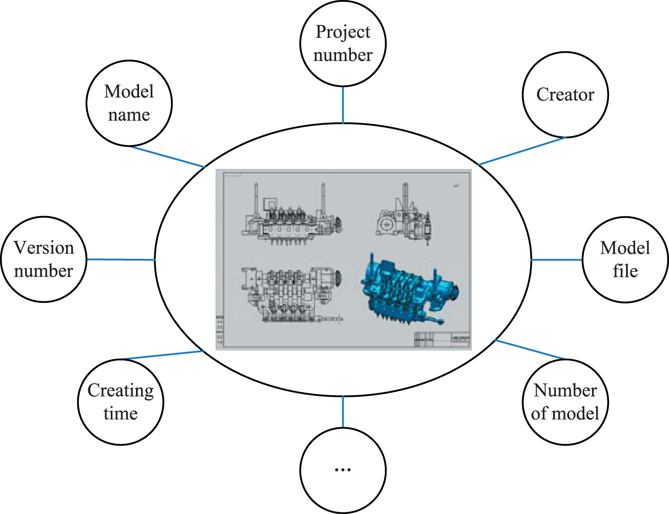
Information model of 2D assembling model of manipulator in cold heading machine.
Properties and corresponding values of 2D model.
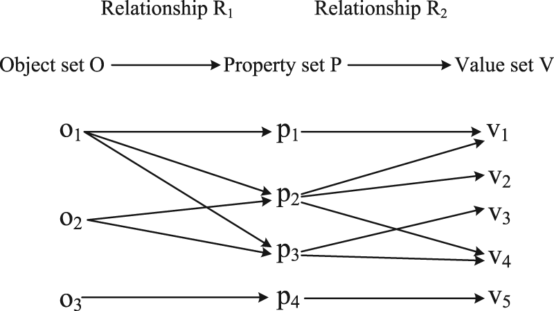
Among the object, property, and value, there is a complicated relationship with the object as the organizational index. According to the VRU model, virtual prototyping includes several objects, while an object may include one or more properties and one property may have one or more values. This characteristic of virtual prototyping can be represented with the relations in set theory, as shown in Figure 5.
The relationship among the object, property, and value.
In Figure 5, the R1 is a binary relation from O to P, and the R2 is from P to V; they are defined as follows: R1 = {<o, p > |o to p, o ∈ O, p ∈ P}; R2 = {<p, v > |p to v, p ∈ P, v ∈ V}. The corresponding relationship from the object set to the value set can be achieved by the relation composition:

The mapping between sets can be defined by the above relations; for example, it can be defined ϕ1 as the mapping from O to P and ϕ2 from P to V. In set theory, ϕ1 and ϕ2 should be surjective, which means that it must have one (i.e. o3 to p4) or maybe more (i.e. o1 to p1, p2, and p3) corresponding properties for each object, and one property can also have more than one object (i.e. p2 to o1 and o2); similarly, it must have one (i.e. p4 to v5) and maybe several (i.e. p2 to v1, v2 and v4) corresponding values for each property, and one value can also have more than one property (i.e. v1 to p1 and p2). So, both ϕ1 and ϕ2 have the mapping relation, such as one-to-one, one-to-many, many-to-one, and many-to-many.
Object-oriented product design resource representation framework for virtual prototyping
Design resource representation framework based on VRU
The design resource representation framework for virtual prototyping is a multi-layered structure. This article proposes a unit model and integrated model of design resources for virtual prototyping. As shown in Figure 6, it is the unit model of design resource representation framework based on VRU.
Unit model of design resource representation framework based on VRU.
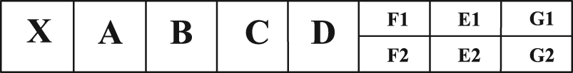
Integrated model of design resource representation framework based on VRU
The integrated model of design resource representation framework based on VRU is achieved by embedding above unit models. The unit models in the same sub-layer are embedded in their parent layer as follows: in the parent layer unit model, E is E2, F is F2, and G is G2; in sub-layer unit models, E is E1, F is F1, and G is G1; the sub-layer unit models are located between F2 and G2 of the parent layer unit model. The integration model uses XML which can visualize the hierarchical structure. By embedding the unit model recursively, the hierarchical knowledge tree is formed, and it can show different knowledge layer by layer.
Figure 7 is a three-layer design resource representation framework based on VRU achieved by the above integration model. If a deeper layer structure is needed, it can be realized by inserting sub-layers continually. The required knowledge can be easily and quickly found through searching in the design resource storage layer by layer.
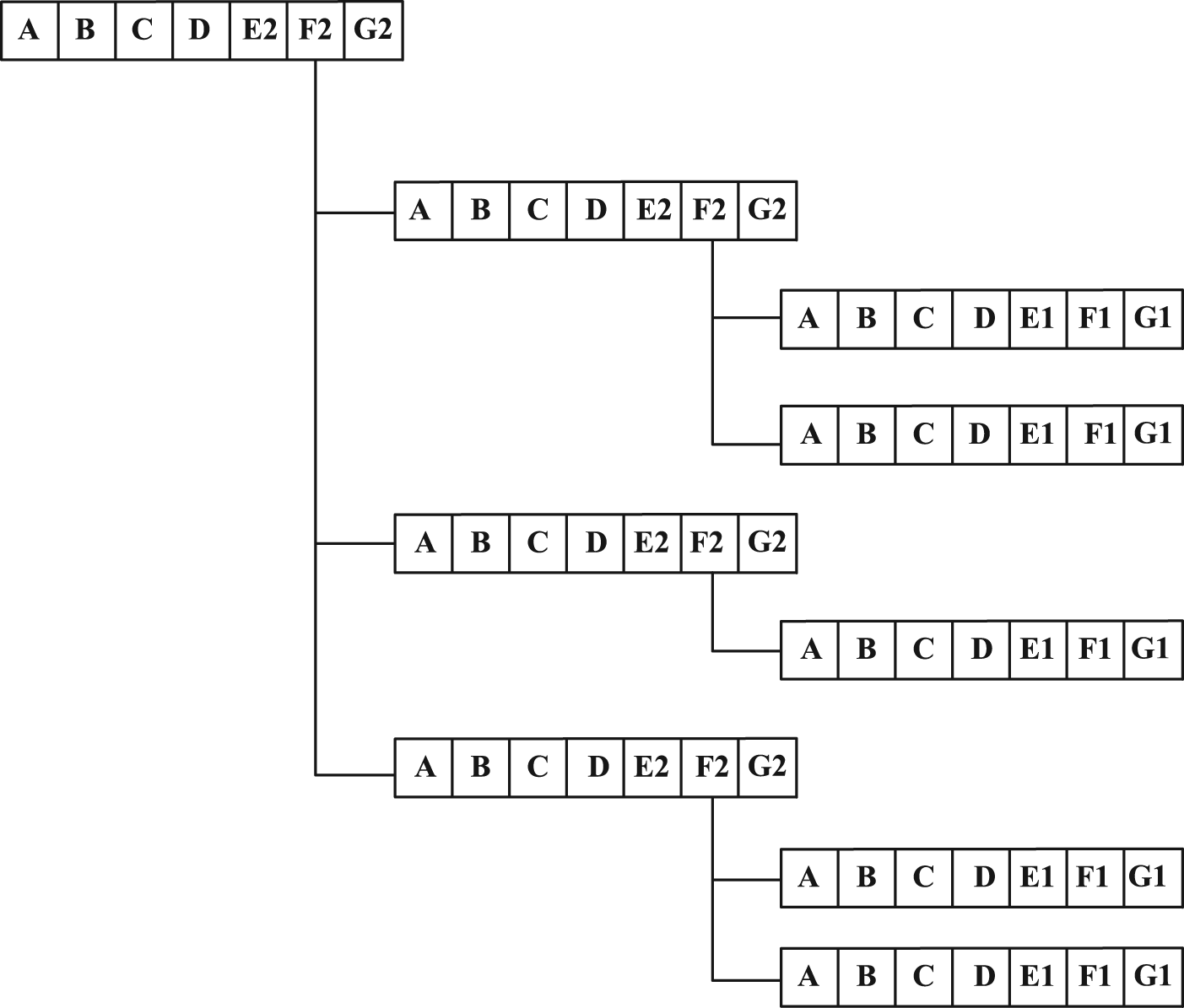
A three-layer design resource representation framework based on VRU.
The code to realize the design resource storage structure of virtual prototyping is shown as follows:
<?xml version="1.0" encoding="utf-8" ?>
<siteMap xmlns="http://schemas.microsoft.com/AspNet/SiteMap-File-1.0" >
<siteMapNode description="Map">
<siteMapNode url="Root.aspx" title="root catalogue" description=" root catalogue ">
<siteMapNode url="Subdirectory1.aspx" title="sub1" description="sub1">
<siteMapNode url="Subdirectory1.1.aspx" title="sub1.1" description="sub1.1"/>
<siteMapNode url="Subdirectory1.2.aspx" title="sub1.2" description="sub1.2"/></siteMapNode>
<siteMapNode url="Subdirectory2" title="sub2" description="sub2"/></siteMapNode>
<siteMapNode url="Subdirectory3.aspx" title="sub3" description="sub3"/></siteMapNode>
</siteMapNode>
</siteMap>
Storage and usage modes of design resource for virtual prototyping
Storage mode of VRU
According to the virtual prototype–based design resource unit model proposed in section “Virtual prototyping representation model,” each virtual prototyping object can be represented by several VRUs. Each VRU (O, P, V) is stored in the database as a data record with three data items: object, property, and value item. So, in the database, a virtual prototyping object is represented by several data records in the structure such as object item, property item, and value item. For different virtual prototyping objects, they can be stored in the same table, and the difference between them reflected in the database is that the record number may vary. By designing the database table in this way, the database can apply to different objects with different appearances, structures, types, and characteristics. The applicability, commonality, and maintainability of the management system developed based on this database are greatly improved.
Through above analyses, all the information of virtual prototyping objects can be stored in the database in one table, while the main entries in the table are object item, property item, and value item. The storage mode of VRU is shown in Table 2.
Storage mode of VRU.
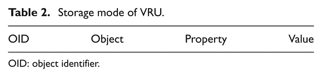
OID: object identifier.
Object identifier (OID) is the identifier of an object, which is unique and constant in the life cycle of an object. The details of the object, item, and value item are divided by the practical requirement of the storage. The definition of OID should include the project information, type information, and the object number of the virtual prototype object. In this way, the layer logic of the virtual prototyping object can be ensured and clearly reflected in the database. As it always needs to be represented by several records in one virtual prototyping object, OIDs of these records are a serial code extended by the basic OID of the record that is first stored into the database. According to the serial OIDs, it is convenient to find out all the records corresponding to the certain virtual prototyping.
For example, for an upper arm of a manipulator, its project number ID is PF-01-1234, its model type (material model and 3D model here) number is 0102, the basic object number is 1101, and the rule to extend the serial number is increasing 1. Meanwhile, for a forearm of the manipulator, the project number is the same as 1234, the model type number is 0102, the basic object number is 1201, and the extended rule is same too. Their storage structures are given in Table 3. OIDs PF_01123401021101 to PF_01123401021105 are corresponding to the upper arm, and PF_01123401021201 to PF_01123401021204 are corresponding to the forearm. In this way, the information about the project, human resource, and the authority management can be represented by the storage structure after appropriate division.
An example of storage structure of a manipulator.
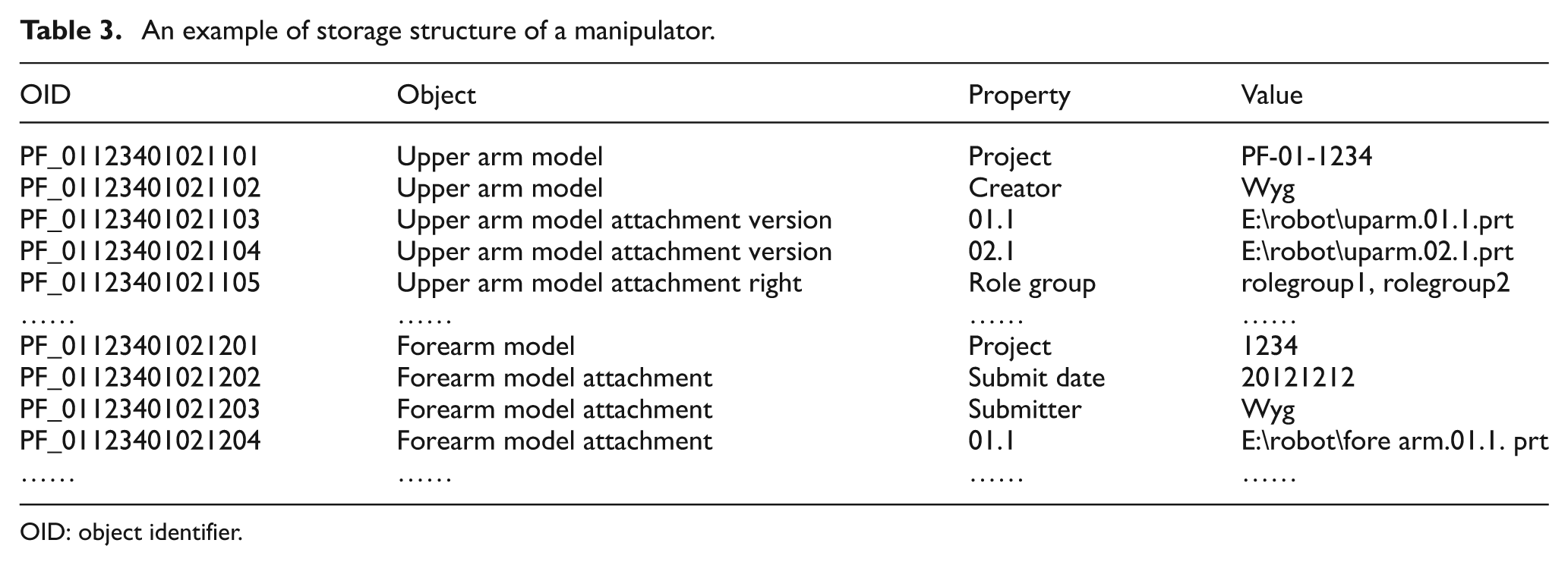
OID: object identifier.
Storage and usage modes of design resource for virtual prototyping
The design resources for virtual prototyping are classified, stored, and retrieved by objects. Each object of design resources has serial OIDs which have no relationship with the physical storage location or with the descriptive way and the value of the data item. They are unique and constant in the system, so various objects can be differentiated by OIDs despite of the content, type, and location.
The object-oriented design resource storage includes two parts: database storage and physical storage. The database stores the basic information about the object in one table with the storage structure (object item, property item, and value item). The physical storage includes data record storage and attachment file storage. The former is the physical storage of the data record in the database table. The physical address of the record is obtained by the hashing OID of the object. The attachment file storage is the storage of the physical file of the object, for example, a 3D model file. The storage address of the attached file is stored as a property in the database table. The value of the property is the specific physical storage address of the file.
Object-oriented design resource storage and operating model for virtual prototyping is shown in Figure 8. A tree information storage catalogue can be obtained according to the instantiation of integrated model in the design resource representation framework. In this article, the catalogue consists of three layers: the root layer, the object type layer, and the object layer. The object type layer has three basic classes: EM class, SM class, and PM class. In each class, there are some sub-class layers to segment the information, for example, the 3D model class and the 2D model class under the material model class. The object layer is the lowest layer in the tree catalogue, under this layer is the list of the specific objects.
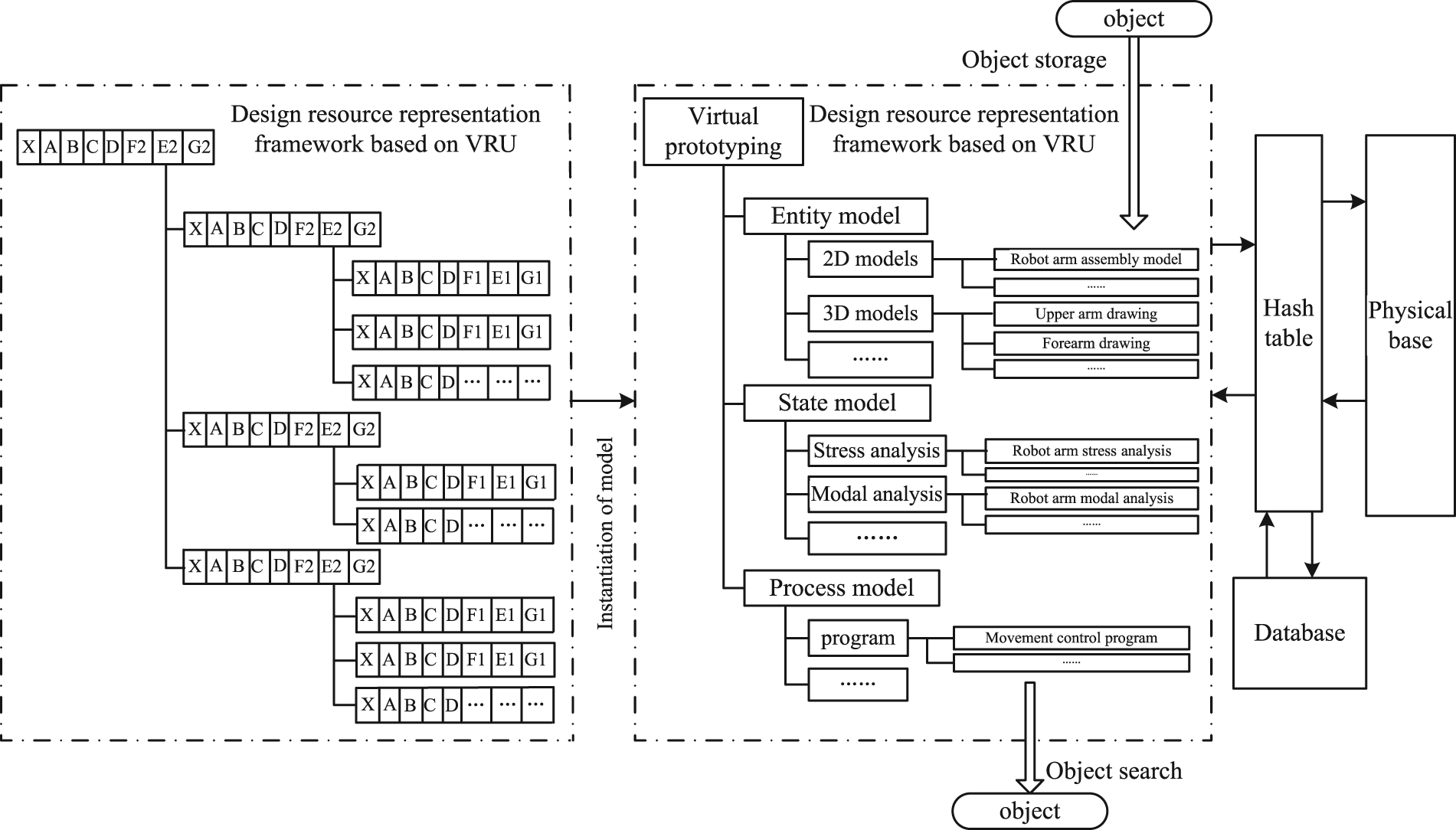
The storage and usage modes of virtual prototyping–based design resource.
When storing the object, first the user enters into the corresponding layer and class in the tree catalogue. Then, the object obtains a serial OIDs assigned by the system, and the physical storage location is obtained by hashing OIDs. Finally, the information about the data records and the attached files is stored in the database and the physical base. When retrieving the object, the user also needs to enter the right layer and class to find the object and then operate according to OIDs.
Storage strategy of design resource for virtual prototyping
According to the object-oriented design resource storage model for virtual prototyping in section “Storage and usage modes of design resource for virtual prototyping,” the objects are stored into the specific layer and class. To realize the process, a storage strategy is proposed as shown in Figure 9. Thus, a function f(i, j) is proposed to found the correct layer and class. The parameter i is the layer ID which is increased by 1 from the root layer to the sub-layer; the parameter j is the class ID which is distributed when the class is created under the layer and determined by the selected class. With the default layer ID (i = 1) and class ID (j = 1), the root layer is opened by the function f(i, j) while initializing the storage catalogue.
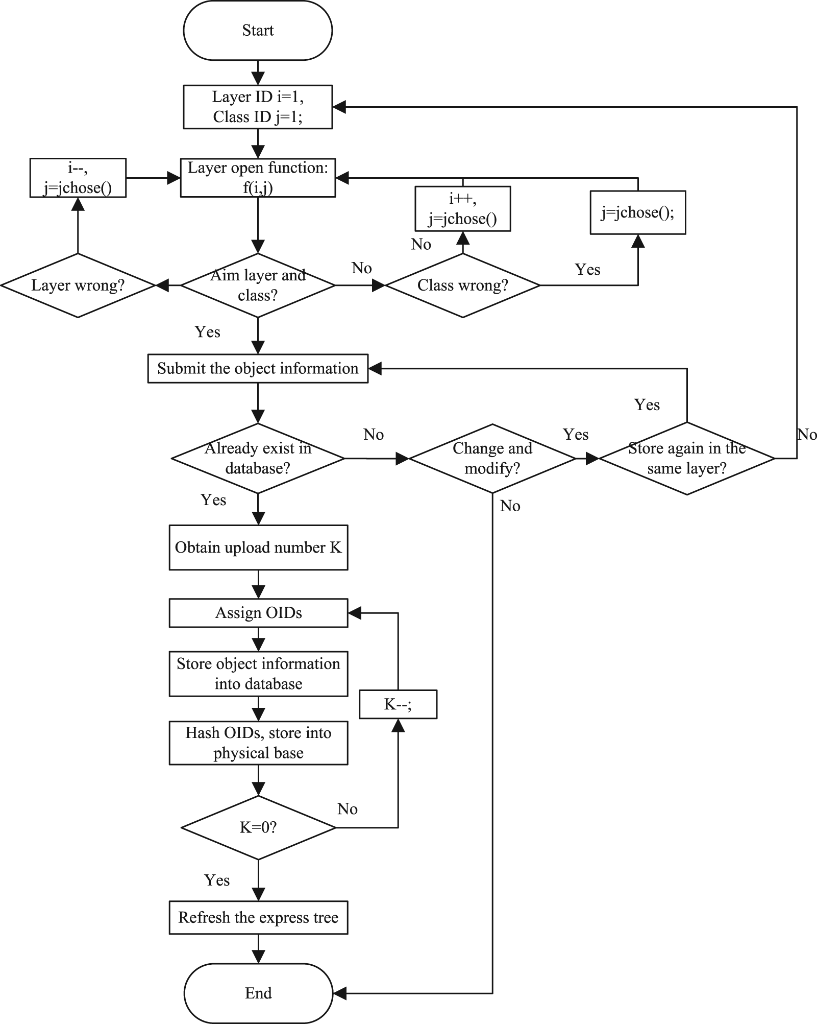
Storage strategy of design resource for virtual prototyping.
The following steps of the storage strategy are shown as follows:
Enter the storage layer and class in the tree information storage catalogue of the virtual prototyping. The function f(i, j) opens the layer and class with the layer ID and the class ID, respectively. The layer ID is increased by 1, based on the default value, when the aim layer and class are the sub-layer of the current layer, and decreased by 1, based on the current value, when the layer is wrong. The class ID is obtained by the function jchose( ), which can find the value by the selected class. If the aim layer and class have been found, go to the next step.
Judge whether the object has already existed in the database. If the object has already existed in the database, the user has two choices: modify the information and store again, or go to the end directly. If the object has not existed in the database, go to the next.
Assign OIDs of the object. First, calculate the upload number K according to the information filled in the user interface. Assign OIDs based on the strategy proposed in section “Storage mode of VRU.”
Store the object in the system. Obtain the storage location in the database and physical base by hashing OIDs. Store the object information into the database. Call the storage function and store the data records into the physical storage area. Judge whether the process is completed by the value of K or not. The number K decreased by 1 when finished the storage of one data record. If K is 0, go to the next.
The storage is completed. Refresh the information storage catalogue of virtual prototyping.
Search strategy of design resource for virtual prototyping
The search process is also a hierarchical process similar to the storage process. First, it needs to enter the right layer and class, then find the aim object, and finally operate with OIDs of the object. To realize the process, a search strategy is proposed as shown in Figure 10. The function f(i, j) is same as the one in Figure 9.
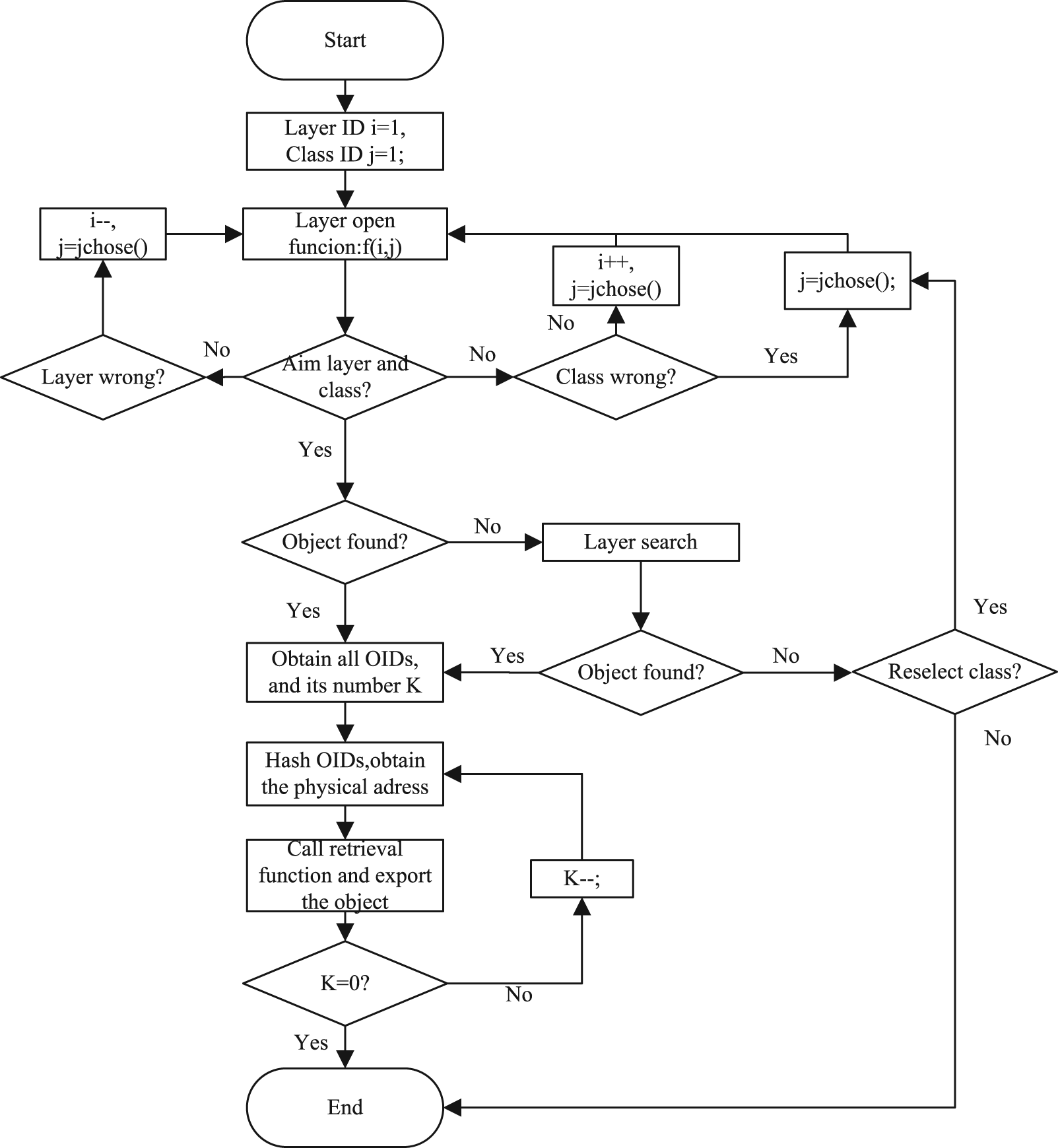
Search strategy of design resource for virtual prototyping.
The specific steps are shown as follows:
Enter the aim storage layer in the tree information storage catalogue. If the aim layer and class have been found, go to the next.
Find the aim object. If the object item can be found directly, go to next. If not, search in the layer, while finding the object, go to next. If the object cannot be found in the layer, the user has two choices: modify the selection of the layer and class and search again, or go to the end directly.
Obtain OIDs of the object and calculate the number K.
Obtain the physical location by searching in the hash table.
Call the retrieval function and export the information about the object. Judge whether the process is completed by the value of K or not. The number K decreases by 1 while finishing the retrieval of one OID. When K is 0, the process is completed.
Version management strategy of design resource for virtual prototyping
In the above descriptions of the design resource representation framework, the objects corresponding to the items in the bottom layer are classified into two types: file type object and information type object. The file type object is a file and its relevant information, while the file is the main object of the management, such as 3D and 2D models of the physical model and the control program in the PM. The information type object is the management information, such as project information, authorization management information, and human resource information. Such objects are managed in the operation interface and stored in the database. In the collaborative design environment, the information object of virtual prototyping mainly refers to the file type object.
It is common that the iteration and modification of documents result in the generation, update, and removal of the versions of documents. There are three modes of version management: linear version mode, tree version mode, and directed acyclic version mode. This article proposed a mode of version management combining the linear mode and the tree mode, and the version is also traced and managed to take advantage of the object data storage model of virtual prototyping. A process of the version management is given as follows.
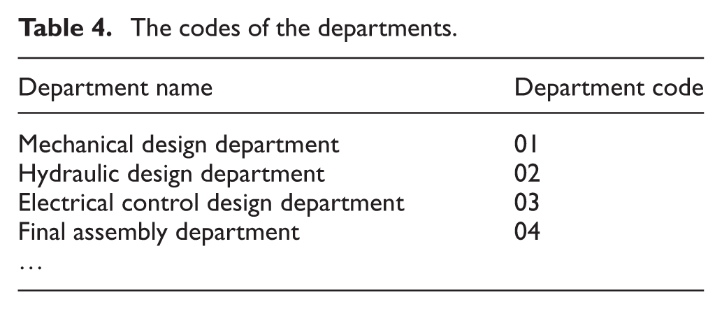
As an example, the company departments are encoded as shown in Table 4. The version number consists of department number and version serial number, for example, A.01.1 means that the document is generated by department 01 (mechanical design office) and the version serial number is 1. If department 01 modifies the document, the version number will update to A.01.2. In this way, on one hand, the process of the document management can be reflected by the version number; on the other hand, it is obvious that which department has modified the current document according to the version number.
The codes of the departments.
It is a version evolution of a document named A in Figure 11.
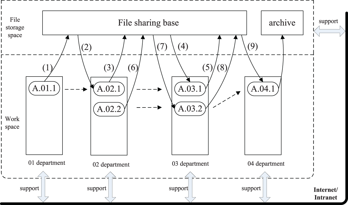
A version evolutionary process of a document A.
The document A was generated by department 01 and submitted to the document share base with the version number A.01.1. The process of document handling was done in private working space (the same as the following).
Department 02 checked out A.01.1 from the document share base and did some modifications.
The new version A.02.1 was generated and submitted to the document share base for an update.
Department 03 checked out A.02.1 and made some modifications.
The new version A.03.1 was generated and submitted to the document share base. But at this moment, the department needed to do some new modifications to the document A.02.1. It operated as the following steps.
Department 02 modified the document A.02.1 again and generated the new version A.02.2. Then, the new version was checked into the document share base.
As the former department has modified the document again, department 03 also needed to modify the new version A.02.2 again and the new version is A.03.2.
The new version A.03.2 was submitted to the document share base.
Department 04 checked out the document from the document share base. The document checked out was the highest version after the handling of the latest department, in this example, it was A.03.02. The new version was A.04.01. Now the process ended, the version A.04.1 was compiled by department 04 and the version was frozen.
Security management strategy of design resource for virtual prototyping
The collaborative design based on virtual prototyping is a complicated process which needs different designers from various departments and roles. After decomposing and assigning design task, each designer must have different roles and rights in the design process. To keep the design system safe, it needs to manage the security of virtual prototyping objects.
The object safety is achieved by authorization management, which verifies the username and password to determine whether the user can log into the system or not. The rights management controls the operating range of different roles. To ensure the system safety, the user can only browse the information limited by his role rights.
The rights assignment is realized via role groups. The role group connects the user and rights. The user can be classified into different role groups, which can be assigned as different rights. The rights of role group include two types: module right and operating right. The module right refers to the visualization of the module, that is, whether the user can see the function module when entered the system. The operating right refers to the right to the specific operations, such as querying, uploading, downloading, modifying, and deleting. The module right is prior to the operating right. Only when the role group had the module right, it can be assigned the operating rights. The role groups which have the same module right may have different operating rights. For instance, the role group 1 and role group 2 in Figure 12; they both have the module right 1, but the operating rights of role group 1 are querying, uploading, and downloading, while the operating rights of role group 2 are downloading and deleting.
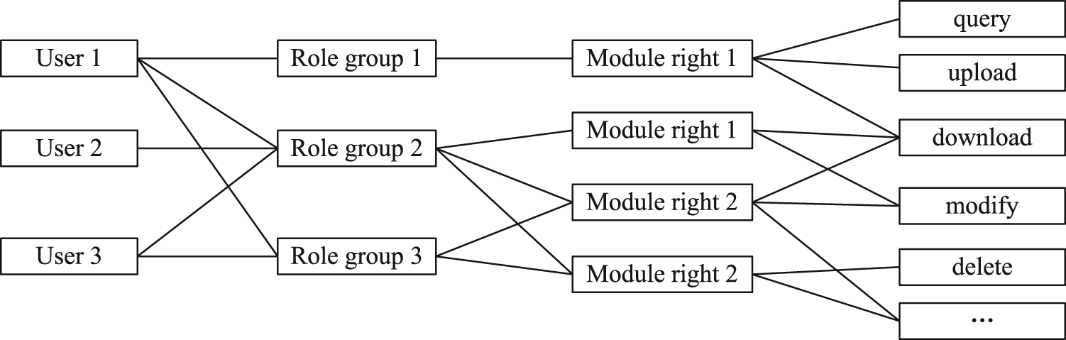
The relationships among the user, role, and right.
Framework of object-oriented design resource management system for virtual prototyping in collaborative design
The framework of object-oriented design resource management system for virtual prototyping in collaborative design can be established as Figure 13.
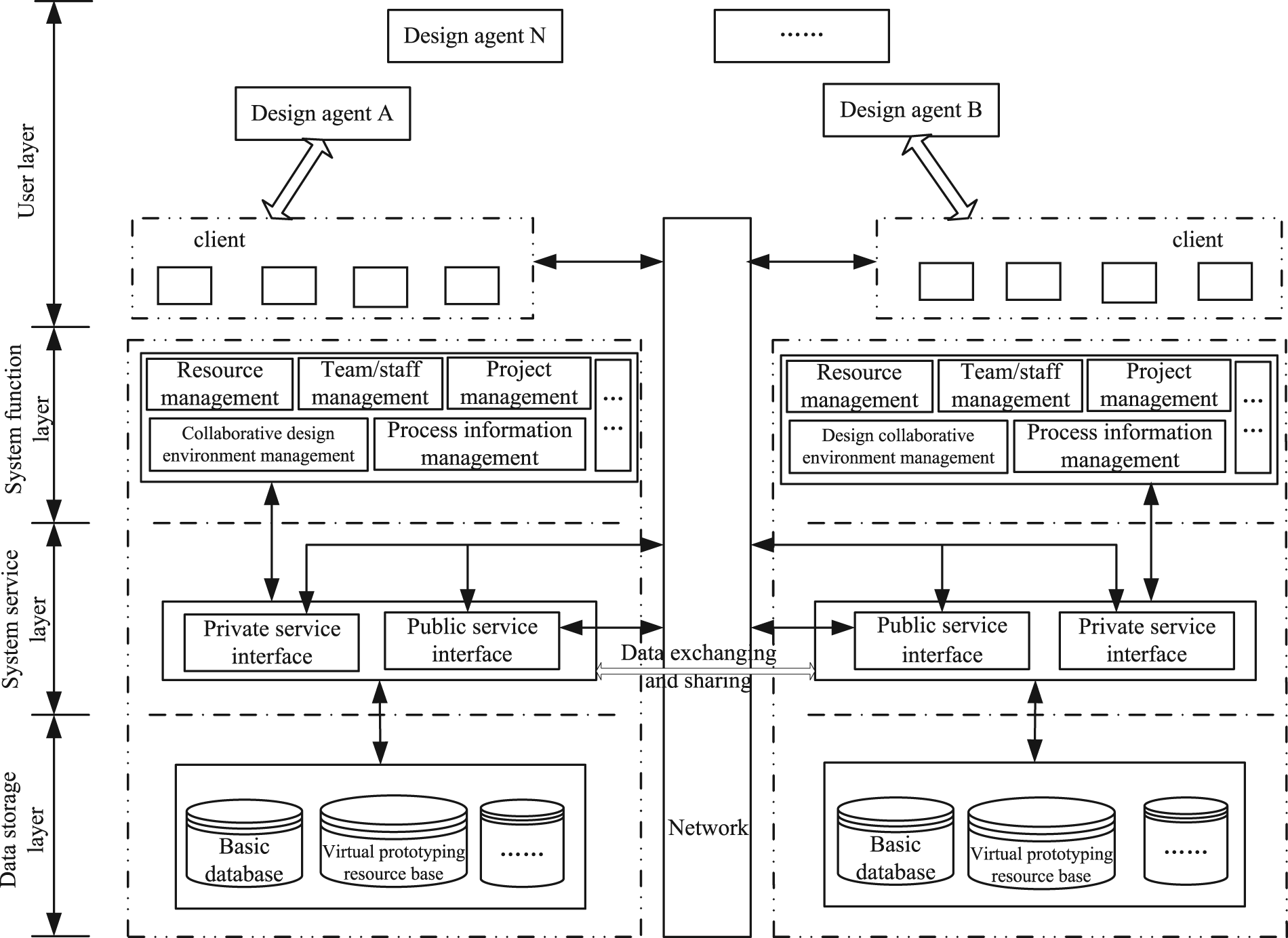
System framework of object-oriented design resource management system for virtual prototyping in product collaborative design.
The model is suitable for the virtual prototyping management architecture with several design agents. It takes two design agents A and B, for example, to explain the collaborative management. Each design agent has a server and a client. The architecture of the server is classified into four layers from bottom to top: data storage layer, system service layer, system function layer, and user layer.
The bottom layer is the data storage layer. In this layer, there are basic database, resource base of virtual prototyping and other database to store design resources and other information about virtual prototyping.
The second layer is the system service layer. This layer provides the web service, mainly the data access service, and it can also do the preliminary logic processing of relevant data and submit the results to the system function layer. The service interface is classified into two types: the private service interface and the public service interface. The private service interface only supports local services which do the logic processing of local data. The public service interface mainly serves for the data exchange and sharing between different design agents.
The third layer is the system function layer. It has a collaborative design environment management module, resource management module, team/staff management module, process information management module, and project management module. This layer mainly deals with the requests from the clients, completes the logical management of the system, and coordinates the design process and resource exchange and sharing between different clients and design agents.
The top layer is the user layer. The client is a web browser; the users operate on the web page and finish the interactive operation between different clients and agents. Different agents connect together through their own public service interface via the networks. Different clients connect to the server through the user layer interface via the networks.
The collaborative pattern of virtual prototyping–based platform with different design agents is shown as follows. After logging into the system through a web browser via local area network (LAN), different agents can design, simulate, and manufacture products in the platform with several functions, such as collaborative management, resource management, team management, process management, and project management. Remote agents can also log into the system via the Internet and use various functions in the collaborative platform.
Application
As one of the most important devices in the cold heading machine, the manipulator is needed to clamp and place semifinished bolts in different places accurately. It involves mechanical design, hydraulic design, control design, and so on. This article took mechanical design and simulation shown as examples to describe the collaborative design mode and the process of object-oriented virtual prototyping design resource management system, as shown in Figure 14.
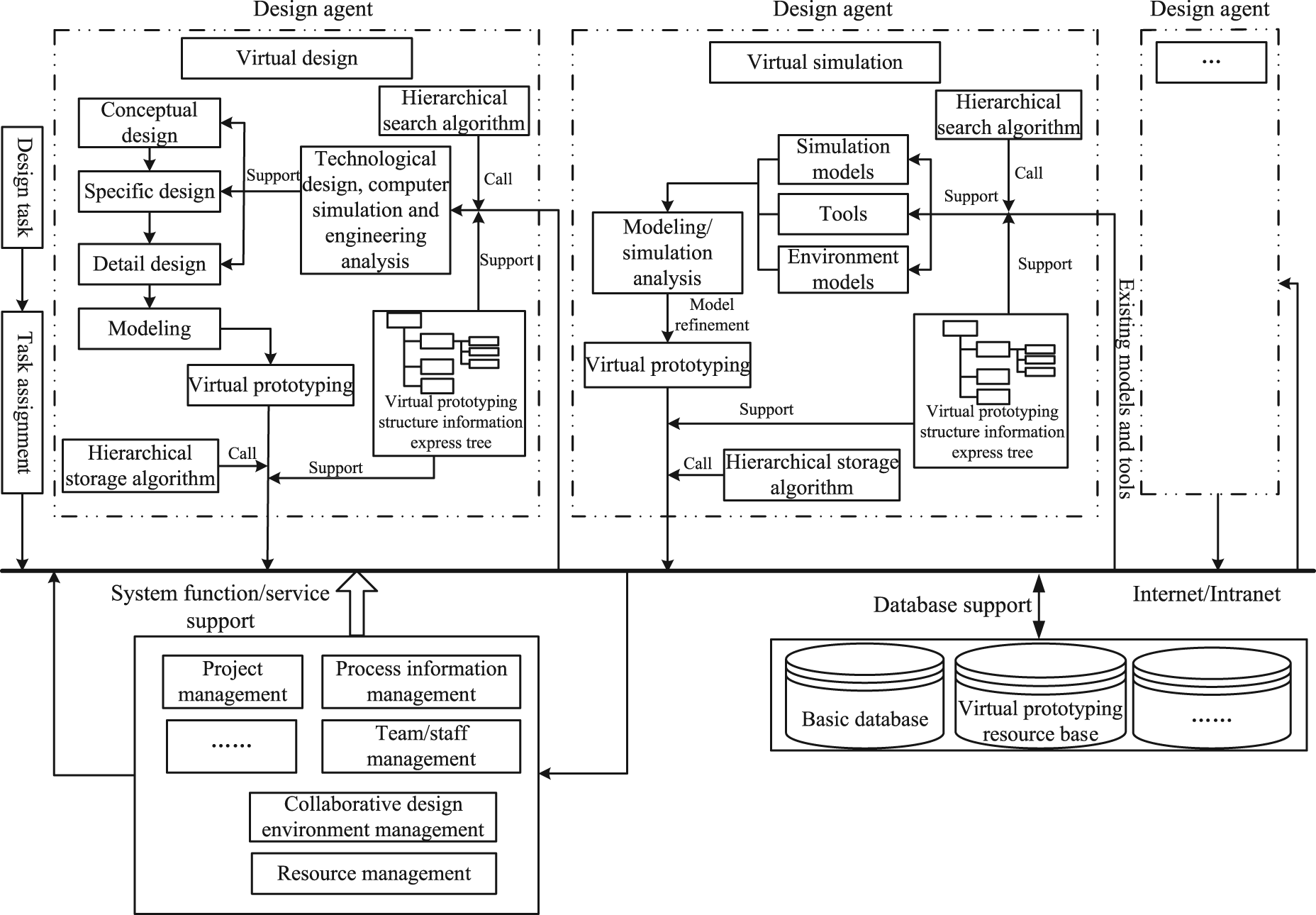
Product collaborative design based on object-oriented distributed design resource of virtual prototyping.
At first, the design task is determined, and then, the task is decomposed into several sub-tasks with task decomposition and distributed to different design agents. The mechanical design of the manipulator is divided into upper arm design, forearm design, base plate design, final assembly design, and simulation.
In this example, there are two types of agents involved in the design process: virtual design agent and virtual simulation agent. In different virtual design agents, the preliminary EMs of upper arm, forearm, and base plate are obtained through conceptual design and detailed design. Then, the information on these models is stored into the database and the virtual prototyping resource base via the hierarchical storage algorithm.
The assembly design agent can import the model files into the working space from the database and the virtual prototyping resource base via the hierarchical search. Then, the component models are assembled into the manipulator physical model. Similarly, the information on the manipulator physical model will be stored into the database and the virtual prototyping resource base.
After the preliminary mechanical design, the virtual simulation agents can import the virtual prototyping physical models (including the component models and the robot model) into the working space and invoke different tools to simulate under the support and coordination by the relational system function modules (such as collaborative environment management module, process information management module, and project management module). Then, the SMs which reflect the simulation result will be stored in the database and the virtual prototyping resource base. For example, to carry out the finite element stress analysis of the manipulator, first the manipulator assembly physical model is imported, then the software ANSYS is invoked to perform the simulation, and finally the information of the SM reflecting the stress and strain is stored into the database and virtual prototyping resource base.
While the simulation is finished, the virtual design agents can perform the optimizations and improvements of the manipulator structure according to SM. For example, according to the SM of the finite element stress analysis, the area of the stress concentration of the manipulator under the maximum load position can be obviously found out. Then, the structure corresponding to the area should be improved, for example, add several floors, thicken the covers, and change the shape of the covers. The virtual prototyping physical model will be stored into the database and the virtual prototyping resource base again after the improvement of the structure. The virtual simulation agent can import the physical models to perform another simulation. After the repeated process, the results meeting the requirements will be obtained ultimately.
The processes described above are supported by the system functions, and the connection between different agents is achieved by networks. By above mode and process, the mechanical design of the manipulator is finished efficiently. The near-optimal mechanical structure meeting the function requirement is obtained.
In the virtual prototyping–based collaborative platform system, there are several important processes, such as project management, resource operation, and authorization management.
In the project management process, it is divided into project approval and project modification. The project information can be created and modified via the interface. The project number is taken as a unique identifier in the system. It will automatically judge whether the project number exists when submitting project information. If the project information needs to be modified, the relevant basic project information can be derived through the project inquiries. Then, the relevant information can be modified if authorized.
In the resource management process, it is the management of basic information and the corresponding attachments with uploading, querying, deleting, and downloading operation. It almost takes a file format as carrier with a wide range of design resources of virtual prototyping. After logging into the appropriate module, the user might fill out all the necessary information, such as the product number, version number, uploading staff, and uploading time, upload the corresponding attachments, and then submit them into the database system. After authorization, the relevant information and documents will be formally stored into the database system. After these files are uploaded successfully, the user can input the project number to conduct the query operation with results displayed in a list form under the authorization. The user should locate and select the appropriate models to delete or download. If permission is not authorized, the user can apply online for relevant permits or just cancel it.
In the authorization management, it is necessary to develop certain permission policies to access resources within authorization, including creating and modifying authorization by the administrator. The module of creating authorization refers to assigning users or role groups to upload, delete, download, modify, and query. Users and role groups can have one or several of these privileges. The modifying authorization refers to modifying the current authorization distribution. After logging into the authorization management module, the administrator queries and selects the appropriate information and documents and selects the types of appropriate operation. If the administrator wants to get the user’s permissions of querying, deleting, adding, and modifying, the authorization information of the corresponding information and documents will be obtained by query.
Using ASP.NET in Microsoft Visual Studio 2005 as the web application development tool and Microsoft SQL Server 2005 as a relational database system, a browser/server architecture–based prototype system, called Virtual Prototyping–based Collaborative Design Platform (VPCDP), has been developed for implementing the proposed object-oriented design resource management system for virtual prototyping in product collaborative design framework.
The system is classified into five modules, including project management module, resource information management module, visualization module, collaborative management module, and system management module. The main function of the project management module is the management of project information and task; the main function of the resource information management module is the model management, model search, and rights management; the main function of the collaborative management module is the collaborative consultation, collaborative annotation review, and collaborative process management; the main function of the system management module is the user management, group management, login management, operation records management, and help.
Figure 15 shows some typical interfaces of VPCDP, including three for defining design resource representation framework based on VRU; user interface for selecting the operation: search exist design resource or new object; user interface for a design resource list of a project, named robot arm assembly drawing; user interface for detailed information of the selected design resource; and user interface for new object.
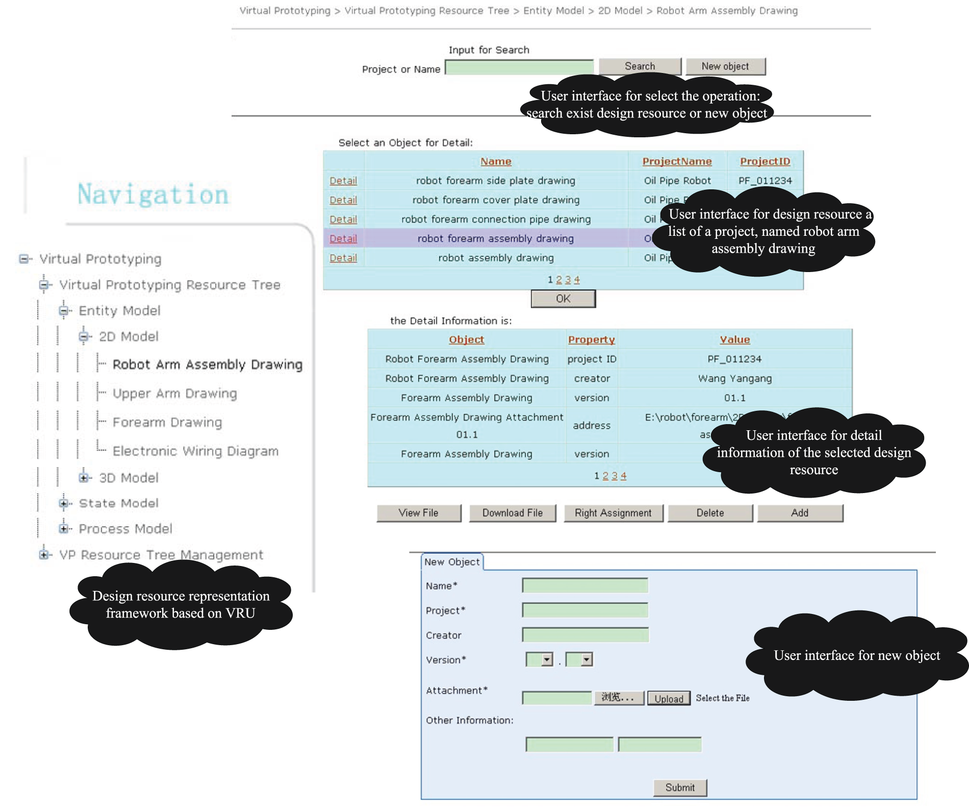
Some typical interfaces of VPCDP.
Conclusion
This article proposed object-oriented design resource management of virtual prototyping in product collaborative design. A formal approach was put forward for object-oriented product design resource representation; mode and strategy for storage, usage, search, version management, and security management of design resource for virtual prototyping are then discussed. After the framework of object-oriented design resource management system for virtual prototyping in collaborative design was set up, the collaborative design process of object-oriented virtual prototyping design resource management system was discussed. A prototype system, called VPCDP, has been developed. The collaborative design of new devices of manipulator in the cold heading machine was given as an example, which demonstrates that the methodology is obviously helpful to reuse and reorganize distributed knowledge for collaborative design. And two concepts have been applied to the State Intellectual Property Office of China for patents. Though significant progresses have been made in the design resource management of virtual prototyping in product collaborative design, there is still a lot of work to be done in the future, such as the development of multi-agent-based system to improve the collaborative mode and the development of the extension of knowledge-based approach for massive information storage of virtual prototyping.
Footnotes
Declaration of conflicting interests
The authors declare that there is no conflict of interest.
Funding
This work was supported by National Natural Science Foundation of China (no. 51305249) and National Science and Technology Major Project of China (no. 2013ZX04002081).