
Abstract
Nowadays, the inspection of formed hull plates is still more dependent on wooden templates. The method based on wooden templates is imprecise, inefficiency and costly. In this article, an alternate measurement sensor for onsite inspection of formed hull plates is developed. The sensor can obtain accurate quantitative result with high efficiency. The case study demonstrated that the sensor could substitute wooden templates to inspect formed hull plates in workshop.
Introduction
Among various techniques, roll bending and line heating are primarily used to form a hull plate by most shipyards. 1 Generally, a hull plate is measured for several times during the forming process of both the roll bending and the line heating. The measurement data are compared with the designed model of the hull plate. If the difference between the measurement data and the designed model is within the allowable error range, the forming process is terminated. Otherwise, the manufacture information (position and orientation) is redetermined, according to the distribution of the difference. And then the forming process is repeated until the difference satisfies the process requirement. Therefore, inspection is essential for the forming process of a hull plate.
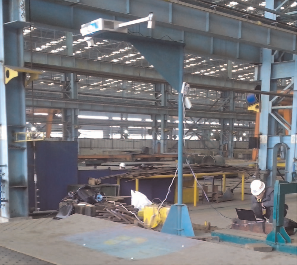
Currently, traditional wooden templates are manually used to inspect the formed quality of a hull pate in shipbuilding industries. Wooden templates can accurately reflect the exact shape of the design model of the plate. Workers place templates on the formed plate and the forming quality is evaluated, as shown in Figure 1.
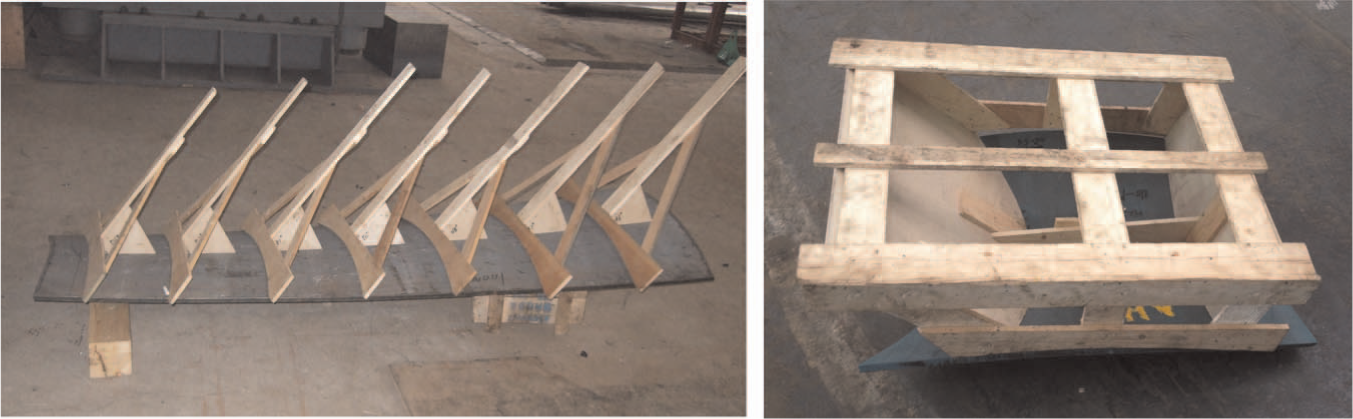
Wooden templates.
However, wooden templates have some shortages. First, workers usually need to prepare quite a few of templates for each hull plate. And these templates are not reusable. Therefore, the inspection method using wooden templates is costly. Second, the shape accuracy of a wooden template is low because the shape would change with the effect of temperature and humidity. Besides that, the measurement accuracy is evaluated only by workers’ experience. Therefore, the inspection accuracy of wooden templates is low. Third, during the forming process of a hull plate, workers have to put wooden templates on the formed surface and after inspection take them off the formed surface over and over again. Consequently, the inspection process of wooden templates is time-consuming and labor-intensive. Finally, the inspection process of wooden templates has no clear-cut methodology because there are no quantitative criteria and the formed accuracy heavily depends on the implicit knowledge of workers. Presently, the inspection method with wooden templates is a bottleneck in the fabrication process of a hull plate. 2
As the traditional inspection method using wooden templates is not suitable for the automated fabrication process of a hull plate, the development of a digital inspection system attracts many researchers’ attentions. Park et al. 3 manually measured curved hull plates using a coordinate measuring machine (CMM) device. The measurement range of the CMM device is 2.8 m×2.8m, and measurement error is within ±0.068 mm. However, the CMM device needs to be operated by workers and its measurement efficiency is very low. Hiekata et al. 4 used a laser tracker to measure a curved shell plate. However, the quantity of scanned points and the use of reflectors would require a very high level of manual effort. Hand et al. 5 proposed a noncontact method to measure the dimension of a ship hull using coherent laser radar. The measurement accuracy can achieve submillimeter. However, the system performs single point-to-point measurement, which is similar to a laser tracker. In order to get a robust and economical solution, Shin et al. 6 adopted a line scanner to collect the measurement data of large-scale hull pieces. For measuring a whole hull plate, the line scanner was fixed on a three-axis unit. However, only a set of three-dimensional (3D) points in a line were got at a time and a lot of work of data processing should be done during the scanning process. Inspired by the wooden templates, Heo et al. 7 proposed a measurement system using fixed four-line structured light without any scanning motion. Theoretically, this method has high measurement efficiency. However, the article does not give a complete and detailed measurement result. Goldan and Kroon 8 adopted the digital photogrammetric to obtain as-built models of curved 3D surfaces of a ship hull combining computer-aided design (CAD)/computer-aided manufacturing (CAM) technology. This method saves the lead time and labor costs. However, the photogrammetric method requires coded targets as auxiliary tools to measure the hull surface. Paoli and Razionale 9 developed a multi-view 3D scanning system by integrating a structured light scanner with a robotic system. The scanner system can offer a precise noncontact 3D measurement of an as-built whole hull surface. However, the scanner projects both horizontally and vertically striped patterns to obtain 3D shapes, which would reduce the measurement efficiency.
Nowadays, developing a fast, robust, accurate and low-cost inspection system for the fabrication of a hull plate becomes a trend in the shipbuilding industry. Stereovision is broadly applied in industrial inspection due to its fast measurement speed, high accuracy, large measurement range and low cost. 10 In order to get a robust performance, some structured lights are often projected to generate artificial texture for easing the stereo correspondence.11–19 A mobile binocular stereovision system combined with multi-line structured light was proposed to measure a large 3D free surface. 11 It used a time-multiplexing code method to encode the structured light. For the online measurement of a hot cylindrical forging, a stereovision-based online structured light was also developed.12,13 This method can measure the diameter of a forming forging in the workshop. In order to obtain a dense stereo correspondence, phase shifting techniques were introduced into stereovision.14–16 As each pixel is coded with a phase value, the pixel-to-pixel correspondence, even sub-pixel correspondence, can be obtained by the phase shifting method. Besides, some methods adopted random illumination to generate texture for facilitating the stereo correspondence.17–19 The random illumination method can also get a dense 3D reconstruction. However, the dense 3D reconstruction will increase the computation cost. Generally, a dense 3D reconstruction is not necessary for a hull plate. To some extent, discrete spaced feature points can sufficiently represent the surface of a hull plate. In this article, a pattern with circular spot array is used to generate these feature points on the surface of a hull plate. Additionally, in order to make the stereo correspondence between different views more robust, each spot is encoded by the Gray code after projecting a sequence of Gray code patterns onto the surface. Therefore, the binocular stereovision sensor developed in this article adopts composite structured light, which combines the Gray code and spot array and is different from other approaches. With the help of Gray code, effects of occlusion, discontinuous and depth step on stereo correspondence can be eliminated. Compared with the method based on multi-line structured light, our stereo correspondence would be more robust even for existing occlusion and discontinuous depth step. Compared with the dense correspondence method, our stereo correspondence has a low computation cost for matching discrete feature points.
However, there are some issues that should be considered to develop a stereovision sensor for onsite inspection of a forming hull plate. First, the size of a ship hull plate is relatively large. And an accurate and rapid onsite inspection is necessary. Second, the workshop environment is generally not ideal. In the workshop, there are some negative factors, for example, vibrations and uneven ambient light. To overcome these problems, some strategies are proposed as follows. First, the structure size of the binocular stereovision is redesigned to get a large field of view (FOV) under the premise of keeping enough measurement accuracy. Second, to quickly recover the structure parameters of the sensor undermined by the vibrations and temperature variation, an onsite structure parameter calibration method is adopted. Third, a stereo-matching approach combining Gray code and epipolar is employed to eliminate the effects of occlusion and depth step.
Compared with wooden templates, the developed sensor is not only more efficient and accurate but also can offer a quantitative result. Compared with other digital inspection systems, the developed sensor has a relatively high cost-effective. The rest of the article is organized as follows. Section “Measurement principle” describes the measurement principle of the sensor. Section “Development” presents the development of the sensor. The calibration method of the sensor is introduced in section “Calibration.” Section “Case study” provides application cases and finally, section “Conclusion and future work” summarizes the article.
Measurement principle
According to the fabrication process and inspection requirements of hull plates, a method based on active binocular stereovision, which used a composite structured light of circular spot array and Gray code, was proposed. Extracting the centers of circular spots and finding the correspondence spots between the left and right cameras are two key processes to reconstruct the 3D model of a hull plate. Next a detailed illustration is presented as follows.
Extracting centers of circular spots
In this article, the method proposed by Chang et al. 20 is adopted to detect the block area of a circular spot. Generally, the centroid and the ellipse fitting are two classical methods to extract the center of a circular spot. Next, an experiment is performed to compare the anti-noise ability of the two methods. A circular spot with center marked by black cross line is projected onto an optical uneven surface. Then the image of the surface is captured and the two methods are used to detect the spot center with different noise levels, respectively. The results are shown in Figure 2, where the green cross line denotes the centroid method and the red one denotes the ellipse fitting method proposed by Fitzgibbon et al. 21 Figure 2 demonstrates that the ellipse fitting method has a better anti-noise ability. Figure 3 shows a case that the centers of circular spots on the surface of a hull plate are extracted by ellipse fitting method.
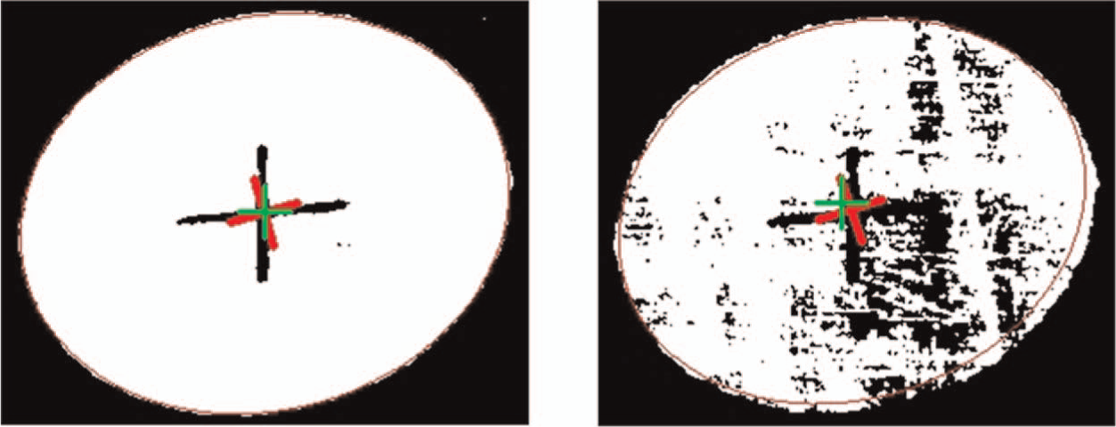
Centers detected by the centroid method and the ellipse fitting method with different noise levels, respectively.
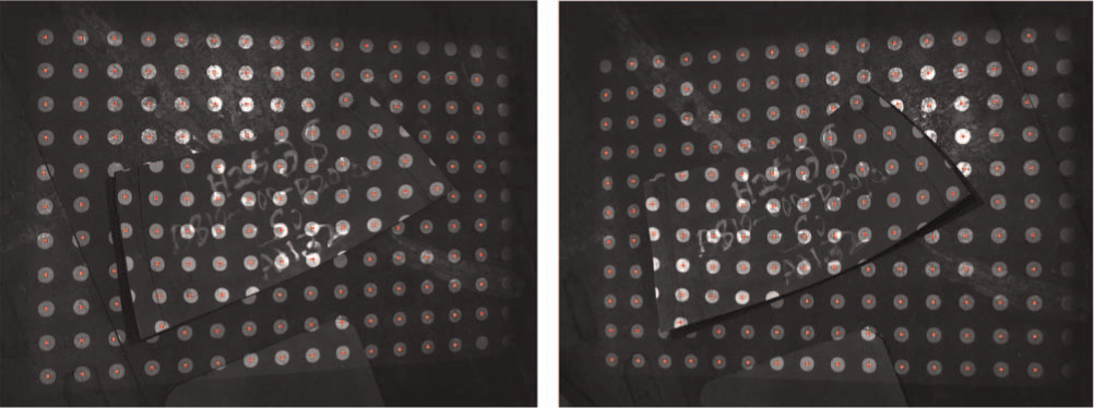
Centers extracted by ellipse fitting in the left and right captured images.
Matching
Before reconstructing a 3D point, matching its two image points in the left and right cameras should be done. A matching method combined by Gray code value and epipolar geometry is adopted in this article. With the help of Gray code, effects of occlusion and discontinuous depth step on stereo correspondence can be eliminated, which makes the stereo correspondence between different views more robust. Besides, with the help of epipolar constraint, a pair of spots having same Gray code in the two views can be quickly matched.
The matching process is mainly divided into two steps: First, project a sequence of Gray code striped patterns onto the measurement scene. The measurement scene is divided into a number of intervals along the direction perpendicular to the stripe. And each interval has a unique Gray code value after decoding. Second, given a point in the left image, the matching point having the same Gray code in the right image must locate on the corresponding epipolar line. The matching process is illustrated in Figure 4. Finally, if a pair of corresponding points has been matched, the corresponding 3D point can be calculated by triangulation. 22
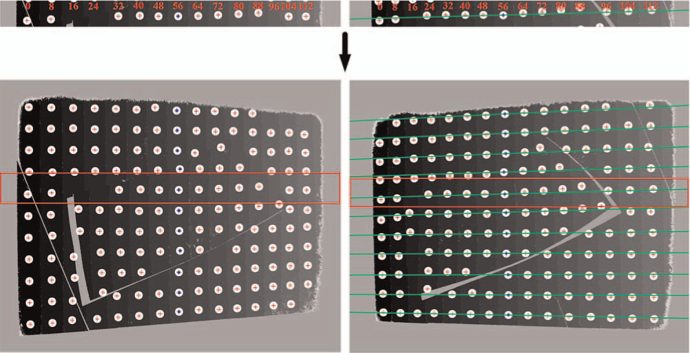
Points with the same Gray code of 56 in the left and right images are matched.
Development
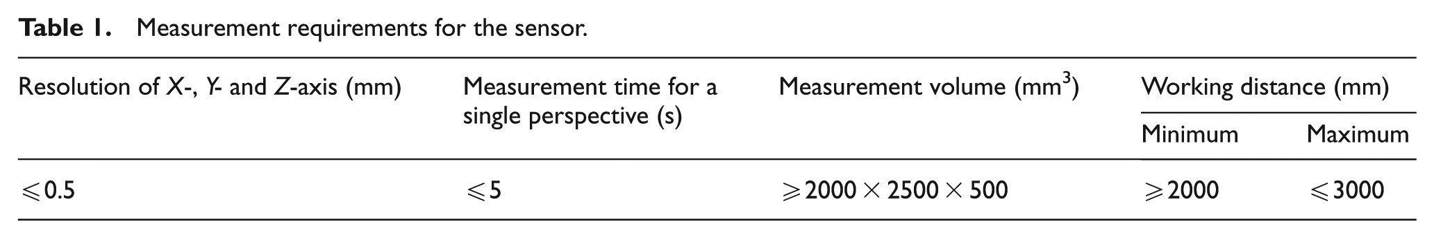
To meet the demand of the onsite inspection of a hull plate, the depth (in Z-axis) and lateral (in X- or Y-axis) resolutions should be not more than 0.5 mm and the measurement time should be less than 5 s for a single perspective. To avoid multiple measurements and data stitching as much as possible, the FOV of the sensor should be large enough to cover most of complex curvature hull plates, whose dimensions are generally smaller than 2000 mm × 2500 mm. The depth range of a formed hull plate in general is smaller than 500 mm. Therefore, the measurement volume of the sensor should be not less than 2000 mm × 2500 mm × 500 mm. Finally, by considering the workshop conditions, the working distance of the sensor should be less than 3 m but more than 2 m. All the requirements are listed in Table 1. According to the requirements, the design working distance of the sensor is set to 2500 mm. Next, the details of hardware parameter selection and structure parameter design will be presented.
Measurement requirements for the sensor.
Hardware parameter selection
From section “Measurement principle,” it can be deduced that the inspection sensor should contain two cameras to compose a binocular stereovision and a projector to project structured light. In order to obtain a better performance, the hardware parameters of the sensor are chosen as follows. The model of lens is PENTAX-C814-5M, whose focal length is 8 mm. In the article, the F-number of the lens is set to 2. According to the lens’s technical manual, 23 it can be deduced that the depth of field (DOF) of the lens is a range of [763 mm, ∞) along the optical axis. The camera sensor is a charge-coupled device (CCD) with 2456 pixels × 2058 pixels, and each pixel is 3.45 μm × 3.45 μm. The acquisition frame rate of the camera can be up to 17 frames per second. A projector with resolution of 1024 pixels × 768 pixels is chosen. The lumen of the projector is 3500 lm.
Structure parameter design
Figure 5 is a structural diagram of a binocular stereovision with two identical cameras, which have the same focal length depicted by
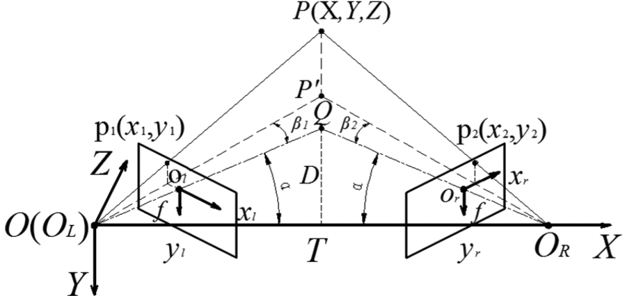
Structural diagram of binocular stereovision.
The projector’s placement has few impacts on triangulation. Therefore, the projector is placed in the middle of the baseline and the projection direction is perpendicular to the baseline, which makes the projection region consistent with the FOV of stereovision. The remaining structure parameters are baseline
Therefore, the task of structure parameter design is mainly to calculate the baseline
In Figure 5, the 3D coordinates of
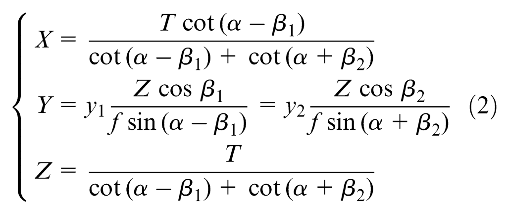
where
The image feature detection accuracy is assumed as
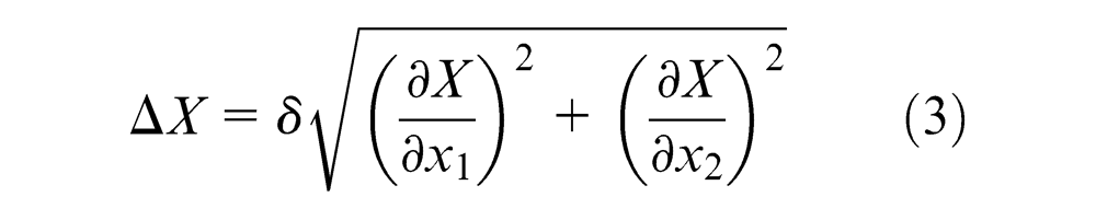
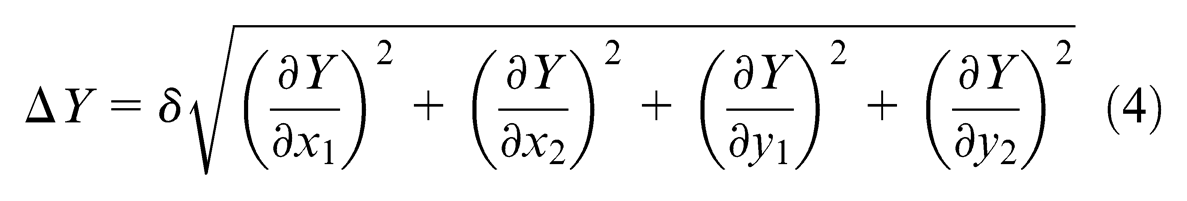
where
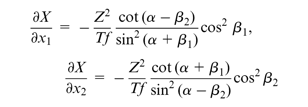
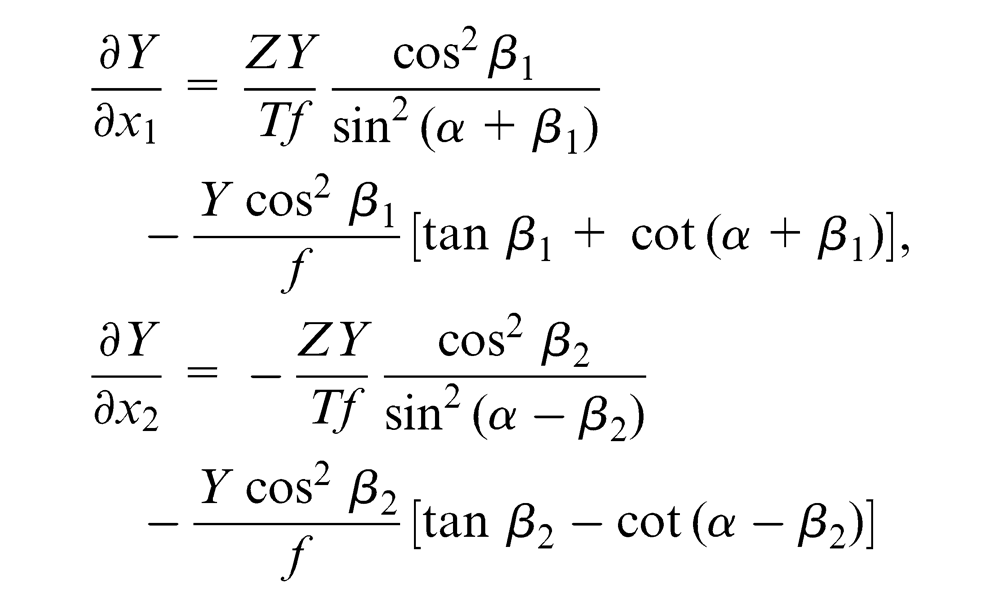
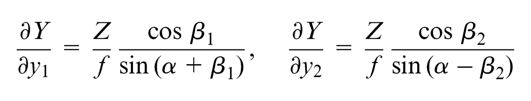
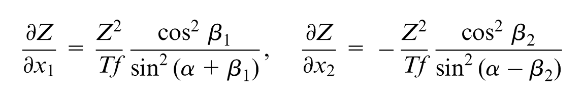
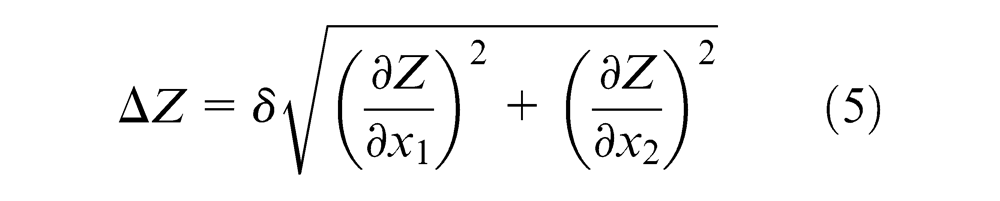
The comprehensive measurement error of
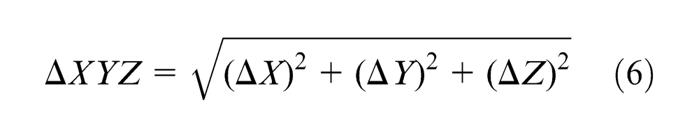
To simplify the analysis, the point


where
From the above context, the focal length of 8 mm is chosen and the design working distance is set to be 2500 mm. Therefore,
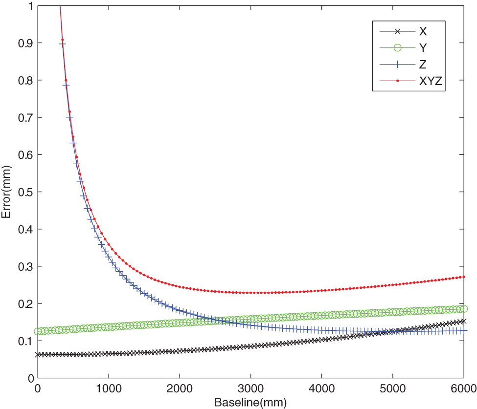
Relationship between the baseline and measurement error.
From Figure 6, it can be found that the comprehensive measurement error (
According to the measurement requirement and above analyses, the baseline of 1500 mm with a comprehensive consideration is finally chosen. Moreover, although the baseline of 1500 mm is still large, two strategies are proposed in this article, which can overcome the problems caused by a large baseline. First, to overcome the matching problem caused by a large baseline, the stereo-matching approach combining Gray code and epipolar is proposed in section “Development,” which is very robust even for a large baseline. Second, to quickly recover the structure parameters of the sensor undermined by vibrations, a periodic onsite calibration of structure parameters with a small target is adopted in the article, which is elaborated in section “Calibration.”
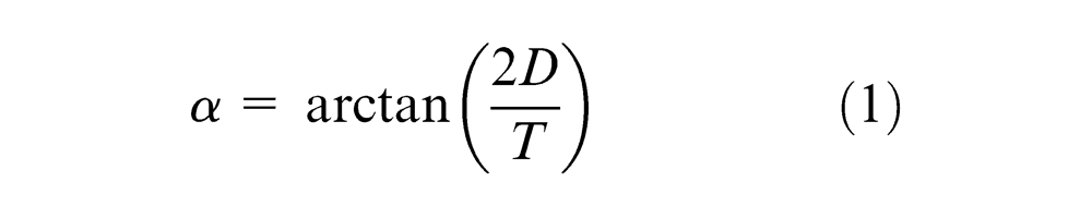
With the baseline of 1500 mm and the design working distance of 2500 mm, it can be deduced that the angle
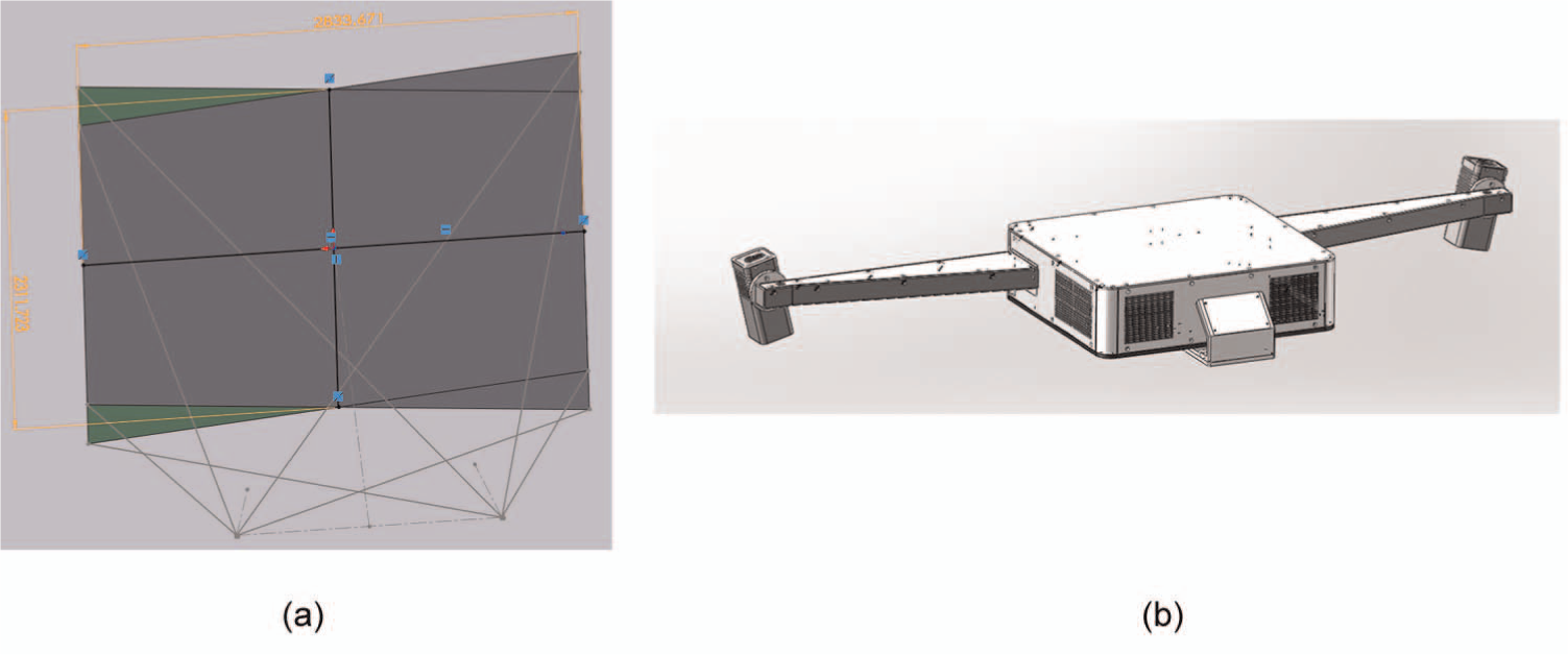
CAD models: (a) the common FOV model and (b) the sensor design model.
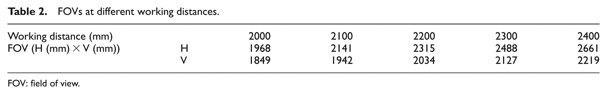
FOVs at different working distances.
FOV: field of view.
In-kind photo of the sensor.
From Table 2, it can be found that the minimum working distance might be a little more than 2300 mm if the required measurement volume listed in Table 1 is considered. However, the maximum working distance could not be determined at present and it needs to be further determined by the accuracy tests in section “Plane object.”
Projection pattern design
Gray code is a binary code. It changes only one bit between two successive Gray code values. With high robustness, Gray code is widely used in structured light 3D measurement. Generally,

where


where
In this article, the projection time of each image is set to 0.2 s, within which the acquisition and processing of the image are completed. Therefore, the total time of the image collection is less than 2 s. The computation time of 3D reconstruction is generally not more than 1 s with the mainstream configuration personal computer. As the time for obtaining the 3D model of single perspective is less than 3 s, the sensor has a high efficiency for a single measurement, which can satisfy the onsite measurement of forming hull plates.
Calibration
Generally, the sensor should be calibrated before the initial use. Additionally, in the use process, the structure parameters of binocular stereovision sensor, especially for the one with a large baseline, are susceptible to vibrations in shipbuilding workshop. For that, the structure parameters will have some changes over a certain period of time. And these changes will reduce the measurement accuracy. Therefore, a periodic onsite calibration of the structure parameters is necessary. As the FOV of the binocular stereovision sensor is relatively large, the traditional calibration target should be large enough to meet the calibration requirement. However, with a large size, the calibration target is inflexible and not easy to be maintained. The large-size calibration target is not suitable for onsite calibration in a complex workshop.
In order to overcome this problem, an onsite structure parameter calibration method for large FOV binocular stereovision with a small target was proposed in our previous work. 27 The method requires that the camera’s intrinsic parameters should be known. They could be calibrated using a large precise rig in an ideal environment such as laboratory. A 55″ LCD with 1920 pixels × 1080 pixels and pixel pitch of 0.63 mm was chosen as the calibration target for intrinsic parameters calibration, which is shown in Figure 9(a). After that, the calibrated cameras and other parts were transported to the workshop. Then the binocular stereovision sensor was set up and the structure parameters were calibrated using a small accurate two-dimensional (2D) target. A 14″ LCD displayer, resolution of 1366 pixels × 768 pixels and pixel pitch of 0.227 mm, was chosen as the calibration target, which is shown in Figure 9(b). As the projector is not directly involved in the triangulation process, it does not need to be calibrated. Overall, compared with the large target, the small target used in the onsite calibration is more efficient, accurate and flexible, which facilitates the application of the sensor.
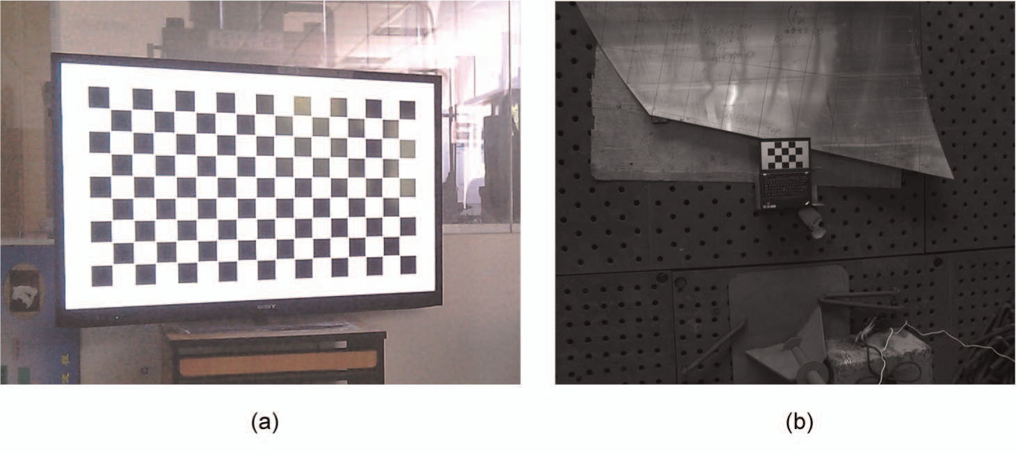
Calibration targets: (a) the large target for intrinsic parameters and (b) the small target for structure parameters.
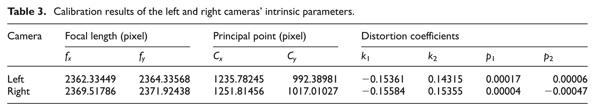
The distortion model containing both radial and tangential distortion coefficients was used. Table 3 lists all intrinsic parameters of the left and right cameras. In Table 3,
where
Calibration results of the left and right cameras’ intrinsic parameters.
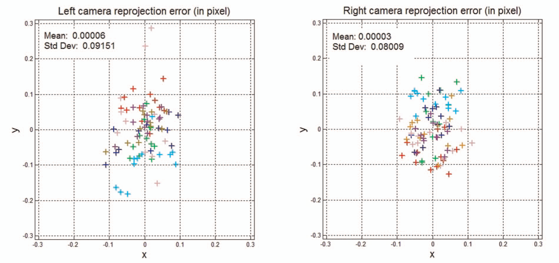
Reprojection errors of the left and right cameras.
Case study
Before practical applications, the resolutions of the sensor should be evaluated. However, it is very difficult for us to evaluate the lateral resolution of the sensor directly. Fortunately, for the sensor, the lateral resolution in theory is more accurate than the depth resolution, as shown in Figure 6. Therefore, the lateral resolution could be indirectly evaluated by the depth resolution. A feasible evaluated approach of the depth resolution is to measure a plane, which has the same direction as the Z-axis of the sensor, at different working distances.
Plane object
A plate with a size of 650 mm × 700 mm is chosen as a standard plane object to evaluate the depth resolution of the sensor. In order to obtain a good result, a region of interest (ROI) with a size of 550 mm × 550 mm is set on the plate, because the ROI is more flat than other regions on the plate. The evaluation procedure is explained as follows. First, the plate is measured by the sensor. Simultaneously, three projection circular spots are chosen as reference points from the projection spot array. And the approximate center positions of the three circular spots are manually marked on the plate. Second, a CMM is used to measure the ROI of the plate again and the three marked points. After that, mesh data with three reference points are obtained by meshing the point cloud reconstructed by the CMM. The mesh surface can be considered as a theoretical model of the plate. Third, according to the three reference points, the mesh data and the point cloud reconstructed by the sensor can be aligned by a 3D software called Geomagic. Fourth, the comparison between the mesh surface and the point cloud is achieved by Geomagic.
In this section, the depth resolutions of the sensor at different working distances, which were 2100, 2300, 2500, 2700 and 2900 mm, were evaluated. At each working distance, the plate was measured for five times with different positions in the FOV of the sensor. A comparison result obtained at working distances of 2500 mm is chosen to show in Figure 11. The standard deviation (SD) that can be regarded as depth resolutions is 0.236 mm. Finally, all the depth resolutions and the mean depth resolution of each working distance are listed in Table 4.
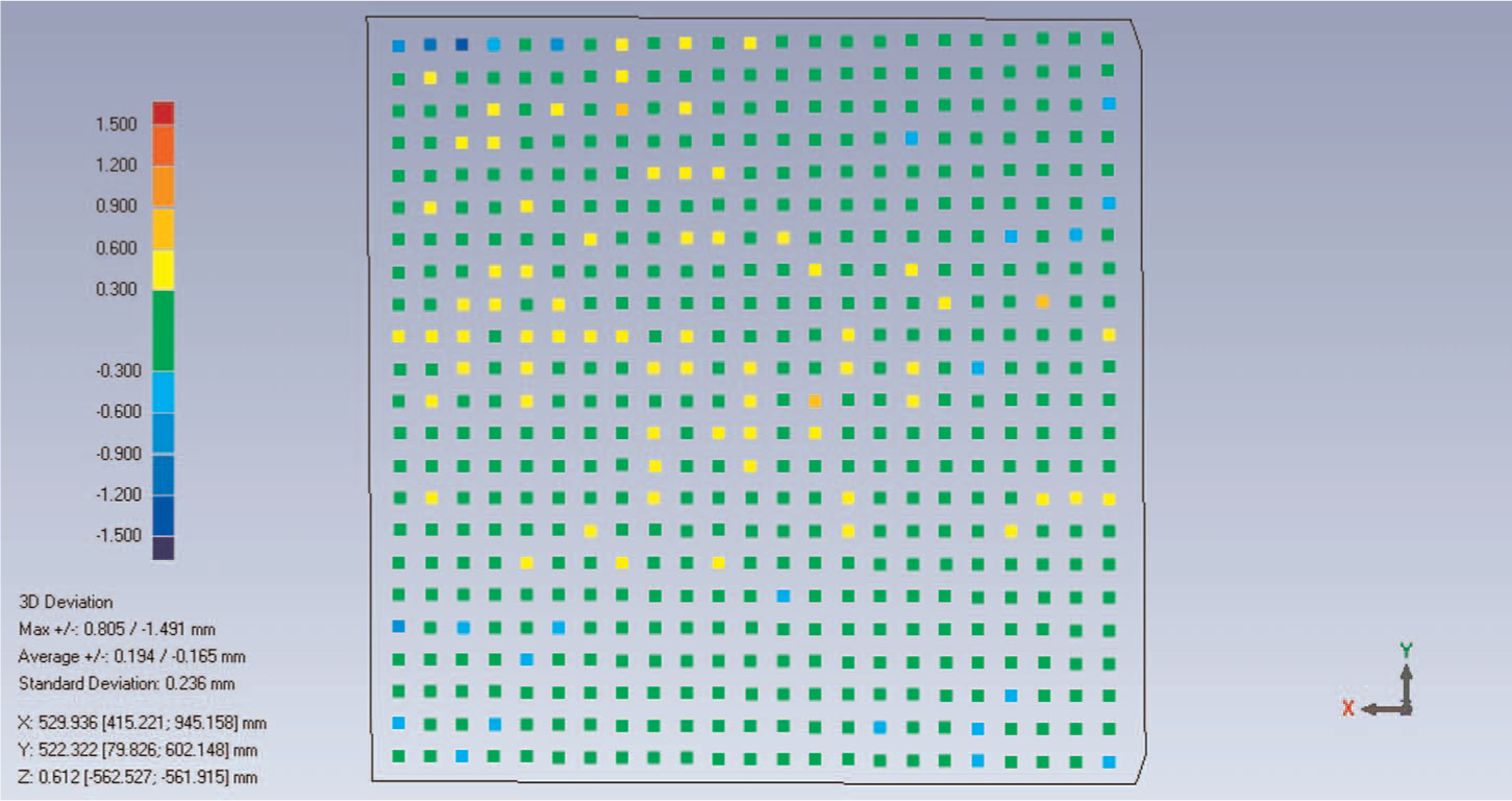
A comparison result at working distance of 2500 mm.
Depth resolutions at different working distances.
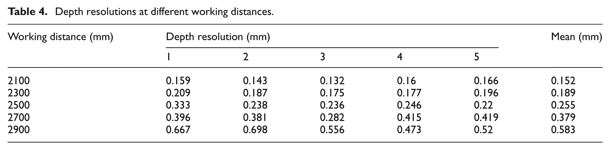
From Table 4, the mean depth resolution at the working distance of 2900 mm is more than 0.5 mm. Therefore, according to the measurement requirements of hull plates, the maximum working distance of the sensor might be about 2800 mm. In section “Structure parameter design,” the minimum working distance should be a little more than 2300 mm. Therefore, the working distance range of the sensor should be about (2300 mm, 2800 mm]. In this article, the design working distance of the sensor is set to be 2500 mm, and both the measurement volume and depth resolution satisfy the measurement requirements. Therefore, the optimum working distance of the sensor should be 2500 mm.
Small-size hull plate
A formed curvature plate with a size of about 1000 mm × 600 mm was chosen as a small-size hull plate, as shown in Figure 12(a). Figure 12(b) shows the CAD model of the hull plate. The measurement process is mainly divided into two steps. The first one is to set three reference points on the measurement surface and then reconstruct the 3D model of the plate. The second one is to compare the measurement model with the CAD model.
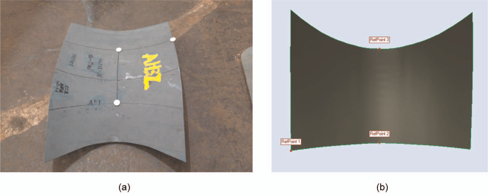
A small-size hull plate: (a) in-kind image and (b) CAD model.
Set reference points
The formed hull plate shown in Figure 12(a) contains a large machining allowance. A problem arises of how to distinguish the true measurement area from the whole measurement point cloud with a large machining allowance. Besides that, in order to make a comparison between the measurement model and the CAD model, these two models must be brought to a common coordinate system that is called localization. To solve these problems, a method based on feature points was used for this kind of hull plate. 28 Three reference circle points were set on the measurement surface, as shown in Figure 12(a). Generally, these circle points locate in frame lines or process lines and each circle point has a corresponding point in the CAD model, as shown in Figure 12(b). Their 3D coordinates can be calculated by the passive stereovision. Then the measurement point cloud of the formed curvature plate can be obtained by the method presented in section “Measurement principle.”
Comparison
First, the measurement model is localized closely to the CAD model according to the reference points, which is called general localization, as shown in Figure 13(a). Second, remove all the reference points, and then a fine localization is implemented using the iterative closest point (ICP) algorithm. This step can establish an accurate localization between the two models. Finally, the comparison error between the measurement model and the CAD model is calculated and visualized, as shown in Figure 13(b). Figure 13(b) shows that the SD is 1.124 mm. The maximum positive deviation is 2.772 mm, which is denoted by the brown ball. The maximum negative deviation is −4.368 mm, which is denoted by the blue ball.
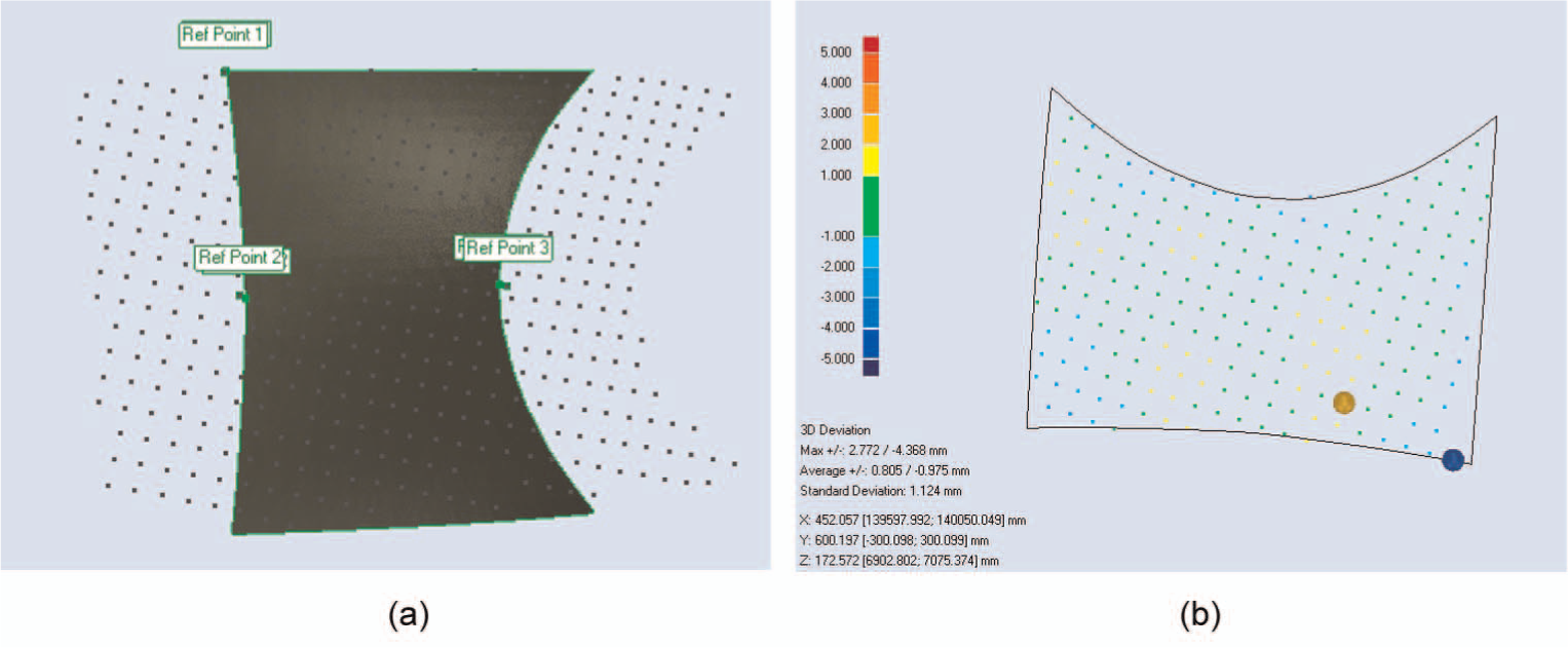
Comparing with CAD model: (a) general localization and (b) accurate localization and comparison error visualization.
Large-size hull plate
Figure 14(a) shows a hull plate with a size of about 2300 mm × 600 mm. Its CAD model is shown in Figure 14(b). In this article, this hull plate is used to demonstrate the measurement process of a large-size hull plate. Generally, a large-size plate should be divided into several small parts to be measured, and then splice all the parts of the measurement data according to some reference points. First, three circular targets were set in the middle of the plate, and then the plate was divided into two parts to be measured at different perspectives. These three circular targets should be measured at each perspective. The two measurement results are shown in Figure 15. And they can be spliced together by these three reference targets. The spliced point cloud and the CAD model were manually registered, which is shown in Figure 16(a). Finally, after a fine localization, the spliced data were compared with the CAD model, as shown in Figure 16(b). Figure 16(b) shows that the SD is 1.186 mm. The maximum positive deviation is 5.652 mm, which is denoted by the red ball. The maximum negative deviation is −4.126 mm, which is denoted by the blue ball.
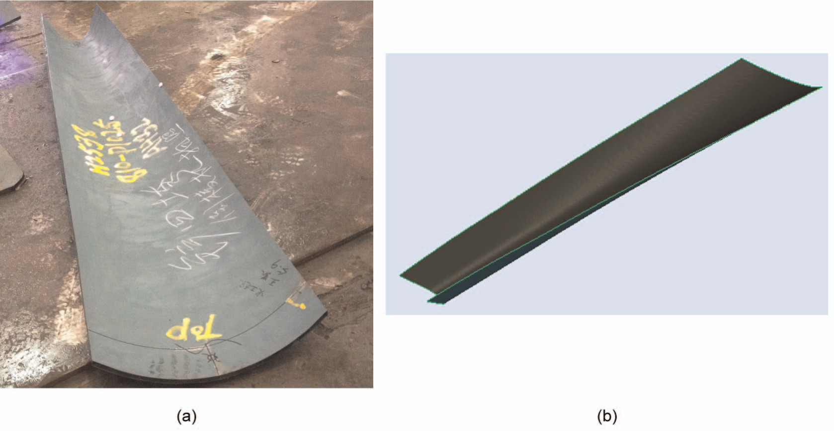
The large-size hull plate: (a) in-kind image and (b) CAD model.
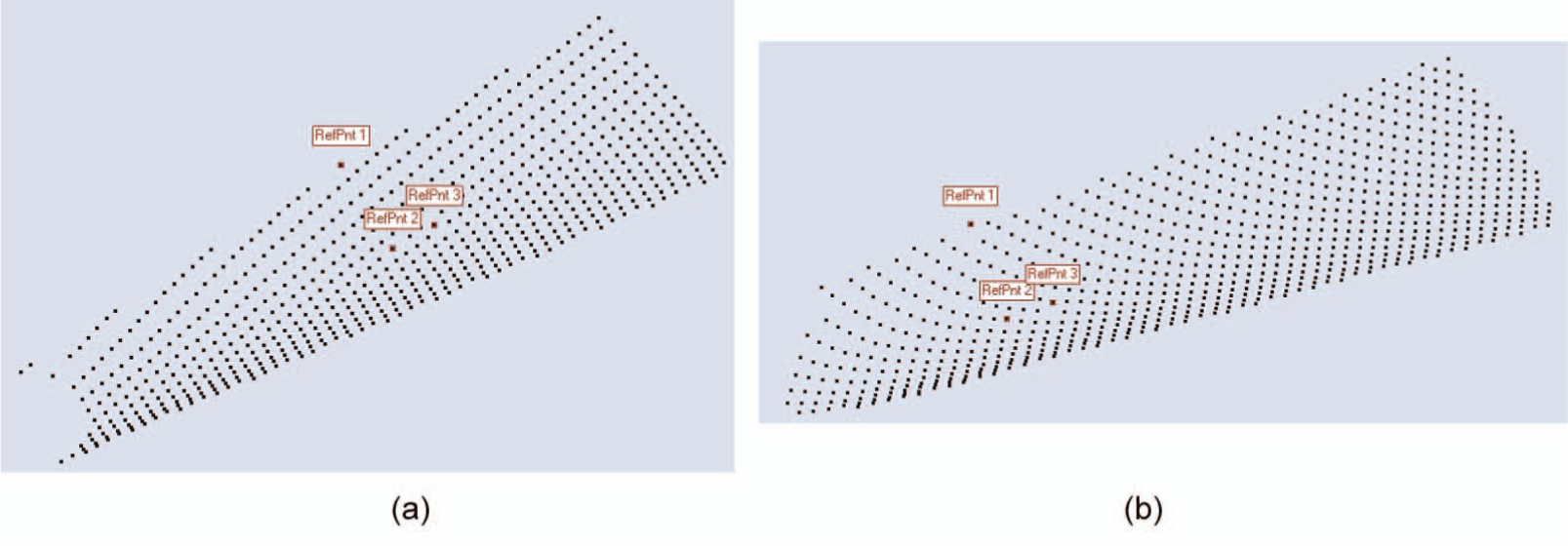
3D point cloud of the large-size hull plate: (a) first part and (b) second part.
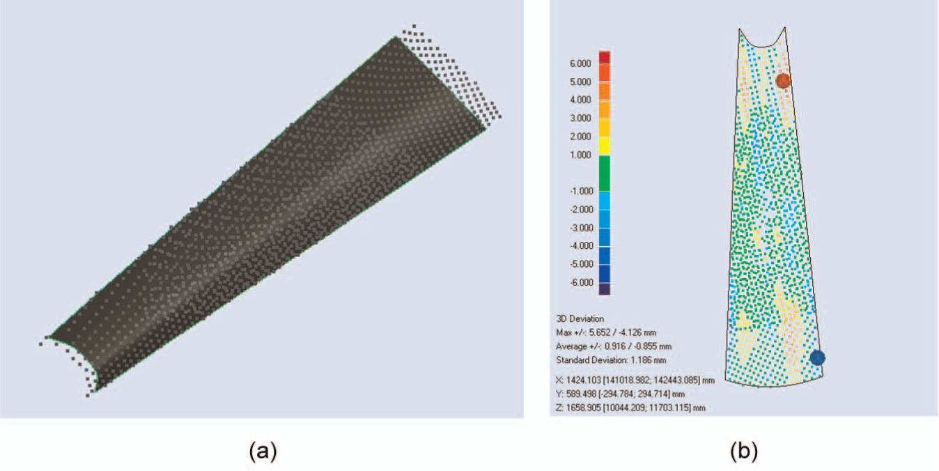
Comparing with CAD model: (a) rough alignment and (b) fine alignment and showing comparison error.
Before using the developed sensor, the formed accuracies of the small-size hull plate and the large-size hull plate were evaluated by corresponding wooden templates, respectively. The inspection result of wooden templates showed that the formed accuracy of the two hull plates met the processing requirements. However, the inspection method based on wooden templates has low accuracy, and it cannot generate quantitative results. Conversely, quantitative errors of the two hull plates, which are 1.124 and 1.186 mm, respectively, can be obtained using the sensor developed in this article. Generally, the forming error of a hull plate is no more than 2 mm according to workers’ experience. The quantitative errors are both smaller than 2 mm, which indicates that the formed accuracy of the two hull plates meets the processing requirements. Overall, the developed sensor can evaluate the formed quality of a hull plate in workshop.
Conclusion and future work
In this article, an active binocular stereovision sensor that is mainly composed of a pair of cameras and a projector is developed. The sensor has some characteristics as follows. First, a composite structured light that combines Gray code and spot array is proposed. With the help of Gray code, effects of occlusion and discontinuous depth step on stereo correspondence can be eliminated, which makes the stereo correspondence between different views more robust even for a large baseline. Second, it has a large FOV. The FOV of about 2800 mm × 2300 mm is obtained by reasonable selection of parts and optimization of the structure at the working distance of 2500 mm. Additionally, the working distance range of the sensor might be about (2300 mm, 2800 mm]. Third, the structure parameters are calibrated by a small target. The onsite structure parameter calibration method can quickly recover the structure parameters of the sensor undermined by vibrations and temperature variation, which facilitates the application of the sensor in workshop.
Finally, three typical objects were tested in the article. The first one was a plane object. By inspecting the plane at different working distances, the depth resolution of the sensor was evaluated by comparing the measurement results with that of CMM. The average depth resolution is about 0.25 mm at the working distance of 2500 mm. The others were two formed hull plates with different sizes. For the small-size one, the sensor measured the whole surface for a time. For the large-size one, the sensor measured it for two times at different perspectives. And then spliced the two parts of measurement data into a whole. By respectively comparing two measurement point clouds with corresponding CAD models of the two hull plates, the SD of the small plate is 1.124 mm and that of the large plate is 1.186 mm. These two cases demonstrated that the developed sensor could substitute the measurement function of wooden templates. Additionally, compared with wooden templates, the sensor is more accurate, efficient and convenient. The measurement result of the sensor is quantitative, which can be seamlessly integrated with other automation equipments.
The full automation of the inspection process and process feedback are our next key work. The full automation of the inspection process without requiring any human intervention is our ultimate goal. Currently, the registering and matching of the measurement data still require some human interventions. For example, to obtain the measurement model from the background, the point cloud segmentation is implemented by manual operation. Additionally, the initial matching is also achieved by manual operation according to reference points. Therefore, in order to realize the full automation of the inspection process, the above manual operations should be avoided and will be further considered in the future. Process feedback is a procedure that projects the comparison results between the measurement data and the CAD model onto the surface of the hull plate. Process feedback can assist and guide workers to do the subsequent processing. The process feedback for the inspection of a hull plate contains three aspects. The first one is the comparison error between the measurement data and CAD model. The second one is machining path generated from the comparison error. The third one is the boundary of the machining allowance.
Footnotes
Declaration of conflicting interests
The authors declare that there is no conflict of interest.
Funding
This work was partly supported by Science Fund for Creative Research Groups of the National Natural Science Foundation of China (Project no. 51121063), National Key Technology Research and Development Program of the Ministry of Science and Technology of China (Project no. 2012BAF12B01) and Shanghai Special Project of Major Technology and Equipment (2012 ZB-ZBYZ-03-11-2810).