
Abstract
In this article, a unique phenomenon called position and inclination interference in stagger spinning process is characterized and investigated. A series of trials are presented to illustrate the causality of visible bulge and concave of wall thickness between position interference, as well as the imbalance and oscillation of roller force. Also, effects of inclination interference have been discussed. Finally, formulae of roller interval selection without interference phenomenon are derived based on the characteristics of position and inclination interference to help exclude invalid combination of roller intervals and guide selection of inclination of roller and blank, which will effectively reduce the amounts of invalid experiments or simulations.
Introduction
Tube spinning, also known as flow spinning, is an efficient process for forming cylindrical hollow parts. 1 In this process, metal is displayed axially along a mandrel to ensure constant inner diameter, while rollers (usually three) feed axially. Significant variations in axial and circumferential wall thickness are occasioned by the local contact with the blank. Advantages such as smaller deformation force loading, hardness increasing, better surface finish and chipless manufacturing make it a particularly attractive technique for production of hollow, axisymmetric components, especially for the automotive industry.
Tube spinning can be divided into forward and backward spinning, depending on the relative directions of roller feed and material flow.1,2 For forward tube spinning, material flows in the same direction as that of roller feed, with advantages including good fittability, high wall thickness reduction, small build-up and bulging. But blank length of this method is restricted by slide stroke and mandrel length. Backward spinning, with an opposite direction, is usually more productive as rollers do not have to feed over entire elongated length, but distortion like bell-mouthing is more susceptible to happen. Backward tube spinning is often employed for cast and welded parts with low original ductility. Both methods have been widely employed in production. Sometimes, joint use of them can also be seen.
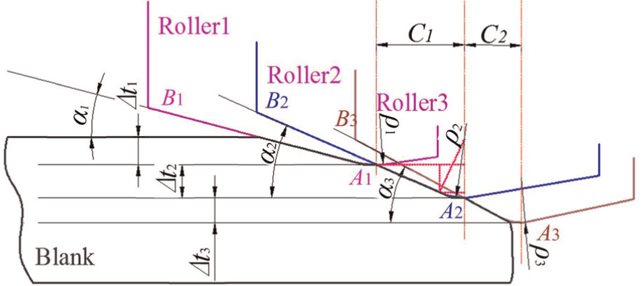
Stagger spinning, as shown in Figure 1, is a special kind of tube spinning in which wall thickness reduction per pass can be undertaken by three rollers at the same time. Rollers are staggered at particular intervals both in axial (Ci, i=1,2) and in radial (Δti, i=1,2,3) directions. Compared with general tube spinning, stagger spinning has higher productivity, shape and dimensional accuracy as intervals make wall thickness reduction be determined by sum of each rollers and increase constraints on deformation area. However, relationship among key parameters affecting quality of products becomes more complicated. Some unique phenomenon such as interference has been generated due to the existence of roller intervals in stagger spinning.
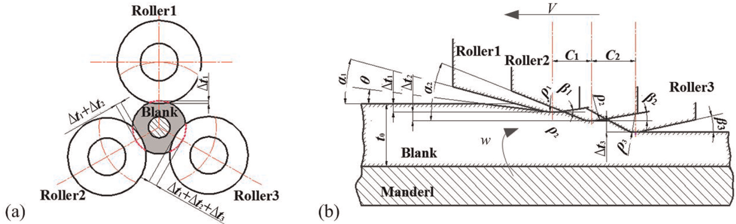
Stagger spinning without interference: (a) distribution of three rollers and (b) principle diagram.
Tube spinning process has been studied by several researchers. Fazeli and Ghoreishi,2,3 Haghshenas et al. 4 and Yao and Makoto 5 analyzed the effects of key process parameters on surface roughness, wall thickness variation and internal diameter growth based on experimental data. Jahazi and Ebrahimi, 6 Murata et al., 7 Su et al. 8 and Kuboki et al. 9 carried out experiments to investigate the effects of temperature and initial thickness deviation on roller force, spinning feasibility and elimination of spinning defects. A set of reasonable parameters have been obtained. Xue et al. 10 and Wong et al. 11 proposed finite element (FE) model to analyze the effects of roller geometry and feed rate. Dariani and Lexian 12 present an analytical contact model for FE analysis. Strain and stress variations,13,14 displacement distribution, 15 bell-mouth, build-up 16 and reasonable parameters 17 have also been studied extensively with FE analysis.
There are also some researchers who concentrate on the stagger spinning now. Xue et al. 18 provided an effective reference for key parameter setting in FE model. Xia et al. 19 obtained influencing sequence of process parameters in stagger spinning on wall thickness, straightness and ovality through orthogonal experimental method. Li et al. 20 and Zhang et al. 21 analyzed the effects of roller intervals on tool forces and wall thickness by the FE method. Gao and Chou 22 and Ge 23 offered formulae for selection of roller intervals. Xue et al. 24 reported that roller feed rate, structure of rollers and intervals have obvious influences on dimensional accuracy, while thickness difference increases little with increase in wall thickness reduction whether for forward or backward spinning.
Importance of roller intervals as the key difference between general and stagger spinning has been confirmed. Majority of previous studies are focused on general tube spinning, while few of them concentrated on stagger spinning. Unfortunately, interference phenomenon that will affect the results of previous studies has not received adequate attention. Interference phenomenon is often found in designed trials of articles that concentrate on stagger spinning as few have pursued studies on it and proposed effective workaround to avoid it.
In this article, two kinds of interference phenomenon, position interference and inclination interference, are proposed. Definition of both of them is given. The effects of position and inclination interference on stagger spinning process have been investigated by FE numerical analysis of tool force, wall thickness, strain and stress variations. Selection formula is derived to help exclude invalid combination of roller intervals and guide selection of inclination of roller and blank, which can effectively avoid interference phenomenon in the design process of stagger spinning.
Modeling method and verification
FE modeling and parameter setting
LS-DYNA commercial code is used to simulate the process of stagger spinning. The FE model consists of mandrel, blank and three normal double-cone rollers that are staggered at particular intervals both in radial and in axial directions, as shown in Figure 2. Three rollers have the same attack and smoothing angle. Considering the thickness of shell element, the outer diameter of mandrel is set as 129 mm. Details of geometrical dimensions of rollers and blank are given in Table 1, so are the process conditions.20,25
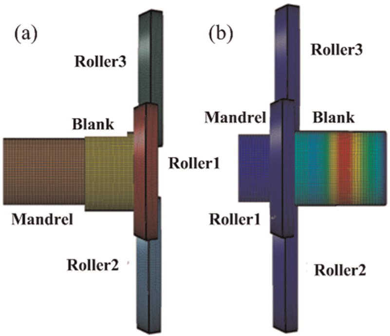
The model of stagger spinning: (a) initial state and (b) the on-going process.
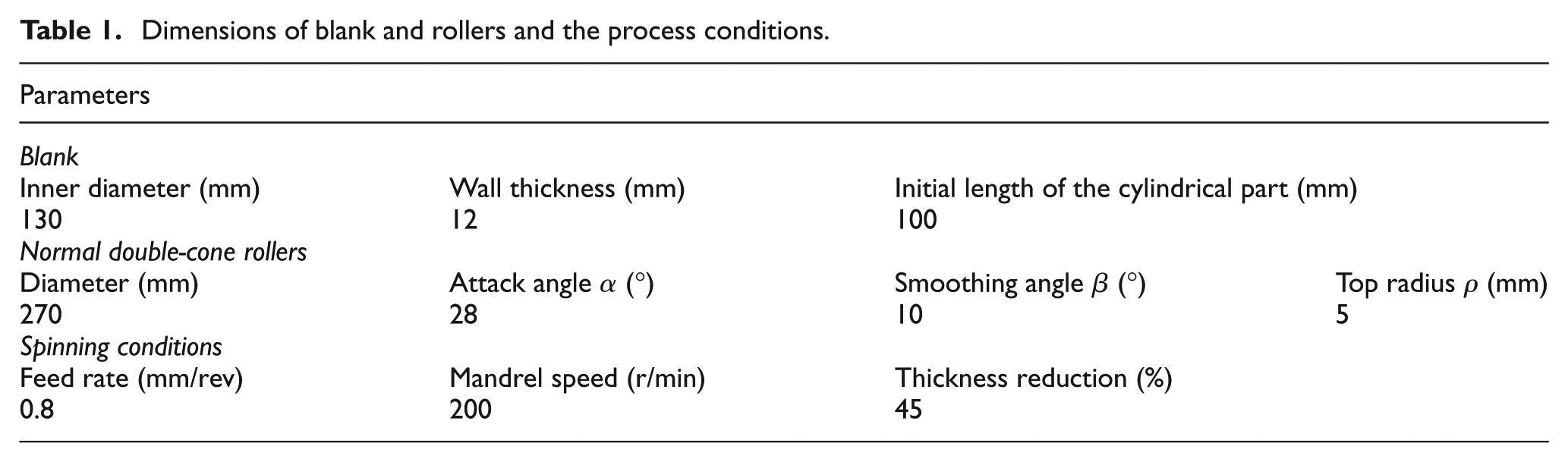
Dimensions of blank and rollers and the process conditions.
In the model of stagger spinning, blank is the only deformable part which is meshed using eight-node hexahedral elements. Different mesh density is applied according to different chamfer angle. The mechanical properties of the material of blank are obtained from the data reported by Li et al. 20 and Wang and Long. 26 True stress–strain curve of the mild steel is presented in Figure 3. Other elastic properties are set as mass density 7830 kg/m3, Young’s modulus 210 GPa and Poisson’s ratio 0.33. The coulomb friction coefficient is set as 0.2 between blank and mandrel and 0.05 between blank and rollers.
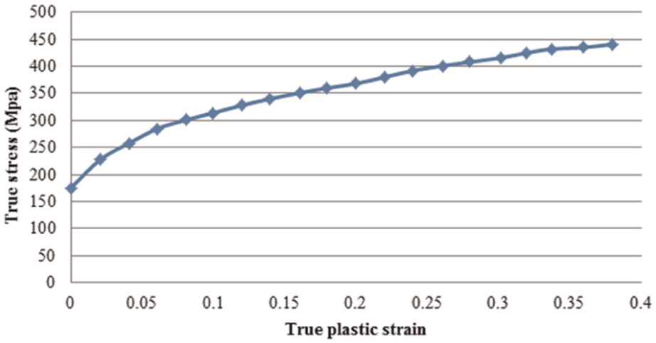
True stress–strain curve of mild steel.
Rollers and mandrel are set as rigid bodies and are meshed with shell element. To simulate actual working conditions, mass inertia is defined for mandrel and each roller, respectively, in local coordinates. Passive rotations of three rollers are implemented. Taking into account the truncation error, double precision calculation is adopted.
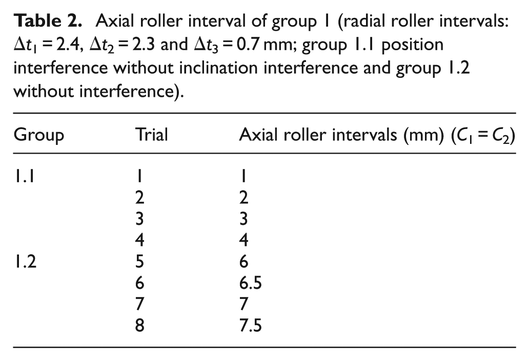
The work presented in this article is aimed at the influence of roller interference on the process of stagger spinning. In order to investigate the influence of position and inclination interference, respectively, two groups of trials are conducted. Separations of results of different kinds of interference have also been taken into consideration. Parameter settings are shown in Tables 2 and 3.
Axial roller interval of group 1 (radial roller intervals: Δt1 = 2.4, Δt2 = 2.3 and Δt3 = 0.7 mm; group 1.1 position interference without inclination interference and group 1.2 without interference).
Chamfer angle in group 2 (axial roller intervals: C 1 = C 2 = 4.5 mm; radial roller intervals: Δt 1 = 2.4, Δt 2 = 1.7, Δt 3 = 1.3 mm; group 2.1 inclination interference without position interference and group 2.2 without interference).
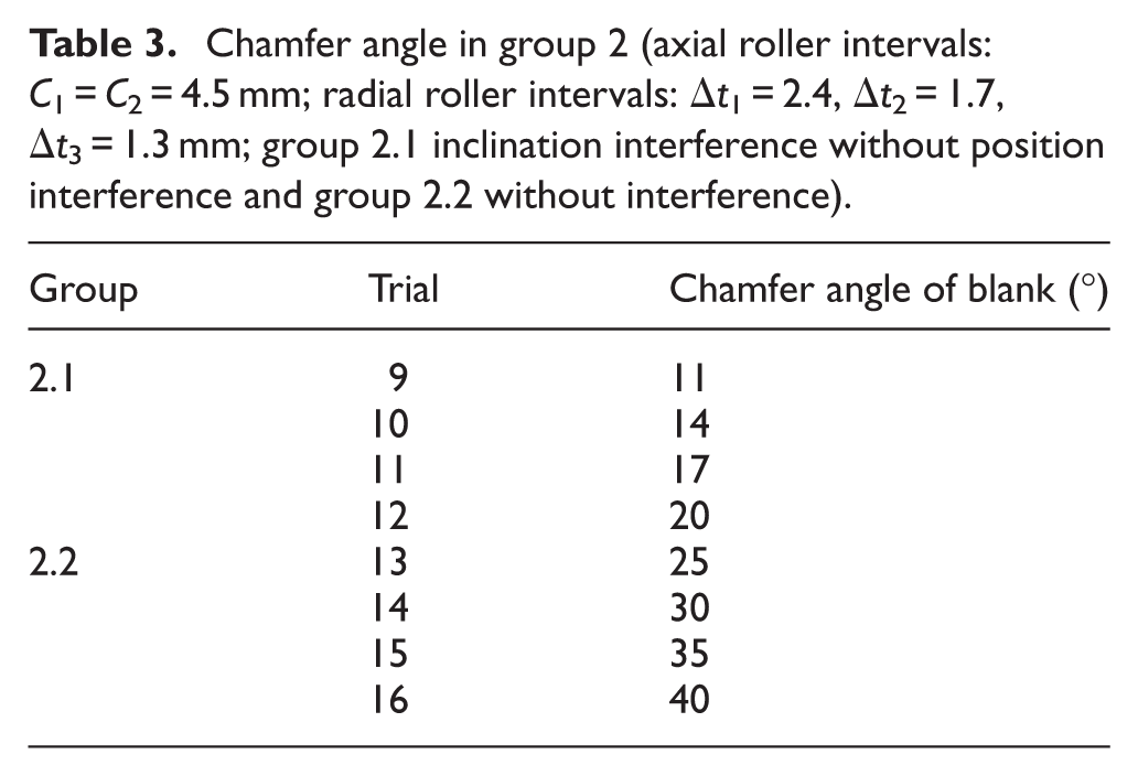
Adjusting both axial and radial roller intervals is an effective way to investigate position interference. Compared with adjusting radial intervals, it is more efficient to adjust axial intervals as only one parameter needs to be considered. For group 1.1, the actual position order of three rollers of each trial in the axial direction is different. The actual order of three rollers in the axial direction in group 1.1 is roller 3, roller 2 and roller 1 in trial 1; roller 2, roller 3 and roller 1 in trial 2 and roller 2, roller 1 and roller 3 in trials 3 and 4. Trials in group 1.2 with the same position order, roller 1, roller 2 and roller 3, are designed to provide a comparison for group 1.1. For group 2.1, position orders of rollers in the axial direction are the same as in group 1.2, while contact orders of rollers with blank are different. The contact orders of rollers with the chamfer angle of blank are roller 3, roller 2 and roller 1 in trials 9 and 10; roller 2, roller 3 and roller 1 in trial 11 and roller 2, roller 1 and roller 3 in trial 12. For group 2.2, contact orders and position orders are consistent. During the whole process, each roller in groups 1.2 and 2.2 undertakes thinning work of itself.
Verification of the simulation
Energy histories have been studied to verify the FE model of stagger spinning. 27 The necessary criteria that ensure FE model being reliable, stable and efficient are that kinetic energy curve of the whole model should be adequately smooth and ratio of kinetic energy to internal energy should not exceed approximately 5%−10% during most time of the simulation process. 28
As shown in Figure 4(a), the kinetic energy increases quickly in a short time at the beginning of the process in trial 14 due to rotational acceleration of blank and feed of rollers. After roller’s contact with blank, it increases gradually to peak and then keeps steady, resulting from the passive rotation of rollers. It is obvious that the kinetic energy curve of the whole model satisfies the smooth criterion.
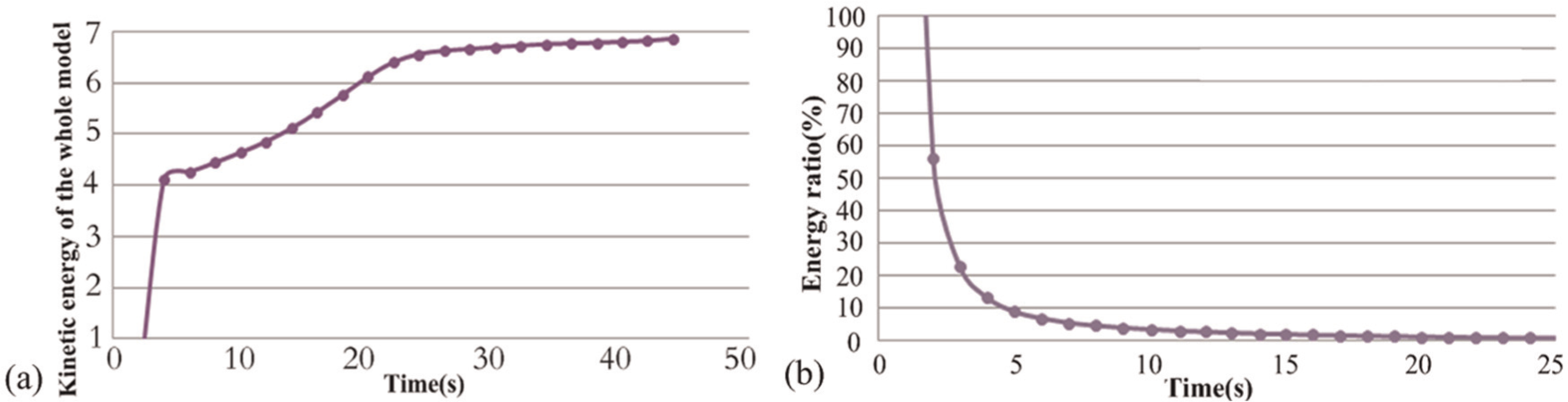
Verification of energy histories: (a) variation in kinetic energy for the whole model and (b) relative values between kinetic energy and internal energy.
The ratio of kinetic energy to internal energy is shown in Figure 4(b). High value of the ratio in the initial state of the simulation results from acceleration of the model. Then, it decreases quickly in about 5 s because of a significant increase in internal energy. The relative value is smaller than 10% for the rest time. So, ratio criterion of kinetic and internal energy has been achieved. Similar result has been reported by Li et al. 20 and Yang et al. 28
Figure 5 compares the results of the processing parameters of forces with the data reported by Li et al. 20 Both radial and axial intervals are set exactly the same. It is obvious that both the trend and values of the ratio of three roller forces are similar. The highest errors between the simulation results and those of Li et al. are 2.5% in roller 1, 2.7% in roller 2 and 2.53% in roller 3. Therefore, it is believed that the simulation results show good agreement with the data reported by Li et al. 20
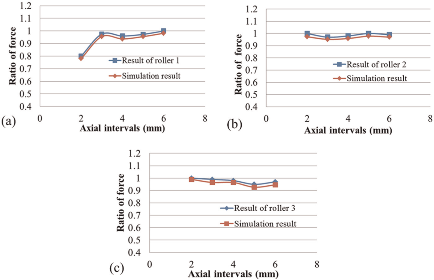
Comparison of ratio of axial force to radial force between simulation results and that reported by Li et al :20 (a) roller 1, (b) roller 2 and (c) roller 3.
Deformation history of plastic strain has been compared with the results reported by Hua et al. 16 As shown in Figure 6, curves of both internal and external elements have almost the same variation tendency, which means that the wall thickness variations are similar. It can also be seen from Figure 6 that the deformation history of internal and external elements is quite different, and similar results have been reported by Zoghi et al. 14
In order to obtain appropriate grid density for model in each simulation, the study of grid independency has been conducted on trials 9–16, respectively, after the effectiveness of the simulation results has been verified for the good correlation with the results reported by former researchers in both the processing parameters of forces and the thickness results of plastic strain. Three models with different grid densities have been designed for each trial. Table 4 provides details of grid density for trials 10 and 13.
Grid density of models in trials 10 and 13.
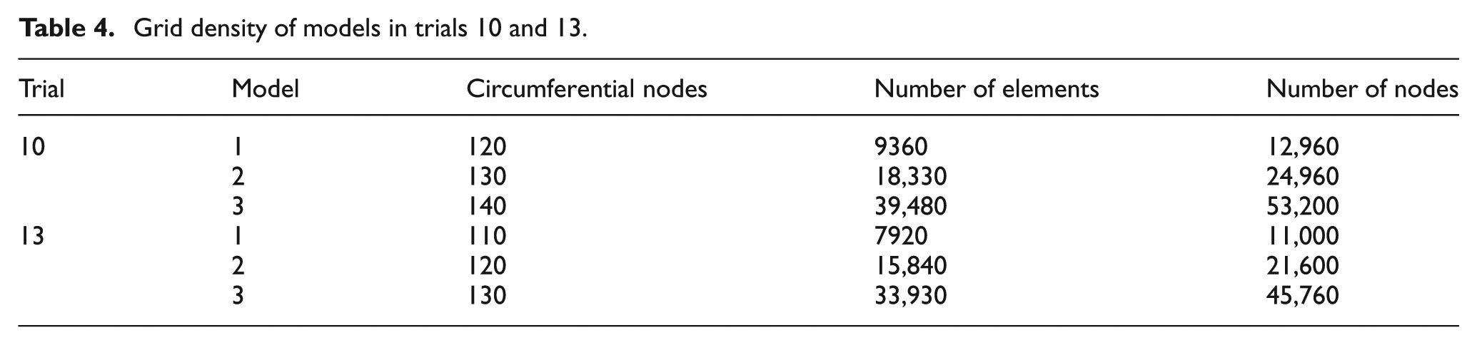
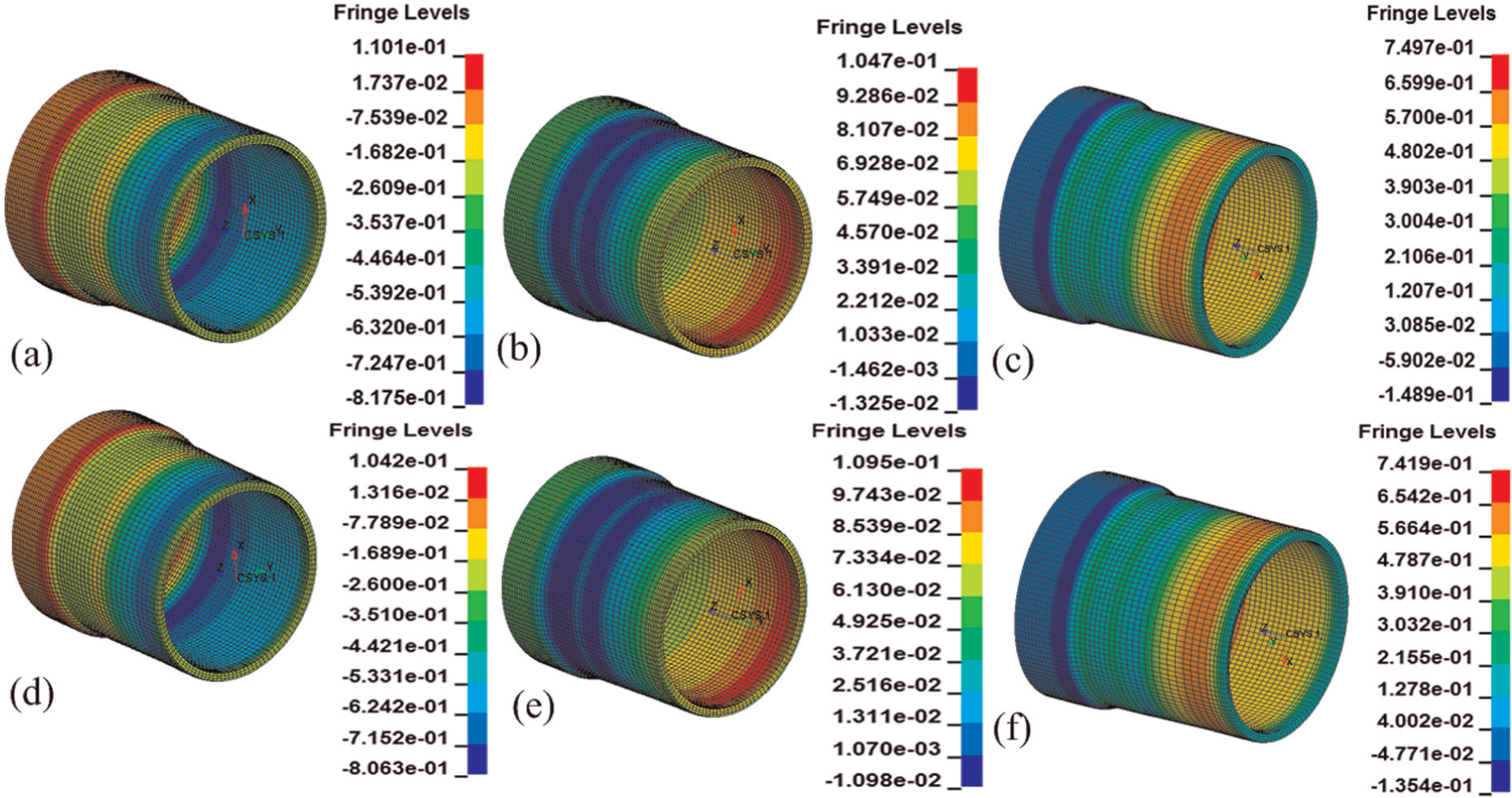
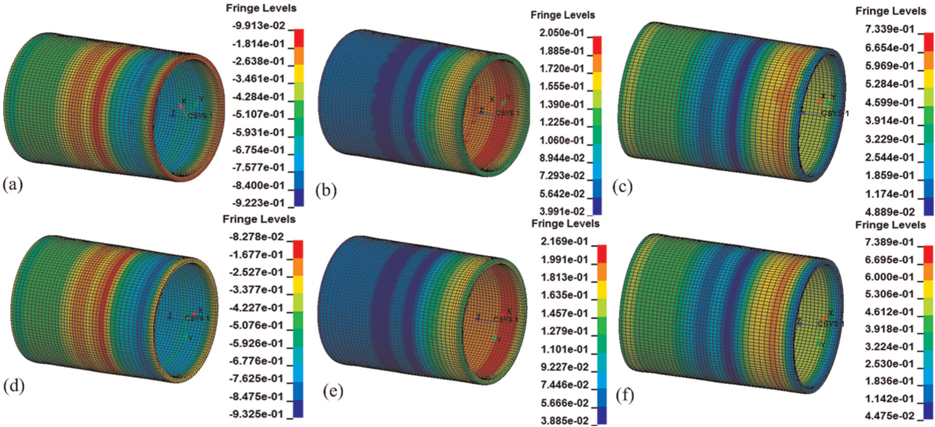
Grid independency has been verified by comparing stresses under different grid densities. 20 Figure 7 shows the von Mises stress distributions of trials 10 and 13. Curves of von Mises stress variations along the direction of roller feed have been shown in Figure 8. The average differences in stress between models 1 and 2 are 14.67% in trial 10 and 13.98% in trial 13. Differences between models 2 and 3 are 1.54% and 2.01%, respectively, which are much smaller than the former one. It is believed that both trials have achieved appropriate grid with density of model 2, which has been used in simulation of this article.
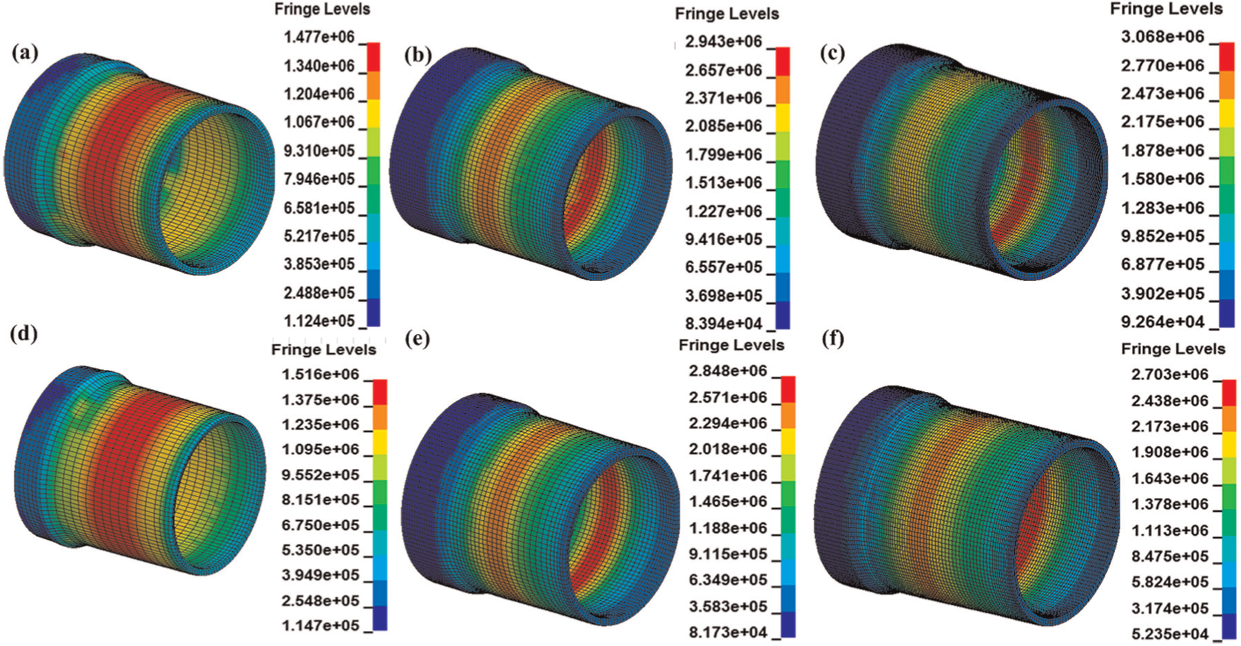
Variations in von Mises stress: (a) model 1, (b) model 2 and (c) model 3 of trial 10; (d) model 1, (e) model 2 and (f) model 3 of trial 13.
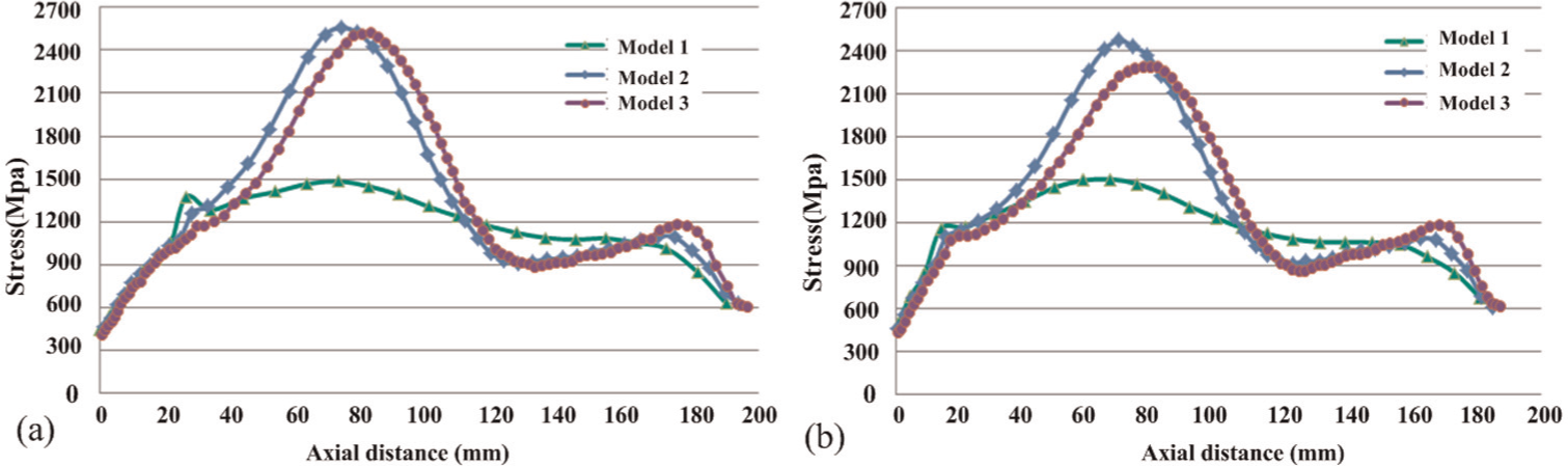
Stress distribution of element along the axial direction: (a) trial 10 and (b) trial 13.
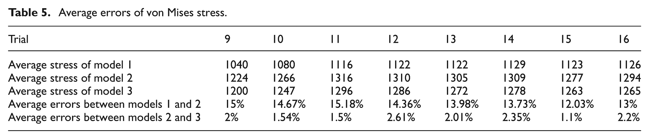
Appropriate grid density of rest trials has been obtained with the same methods. Difference in average stress between the three models of each trial is shown in Table 5. For other trials in group 2, trials 9 and 10 have the same grid density. Grid densities of rest trials are consistent with those of trial 13.
Average errors of von Mises stress.
By the above comparisons, it is obvious that the suitable parameter setting of FE analysis of stagger spinning, such as grid type and density, boundary condition, passive rotation, mass scaling factor, stiffness coefficient and mechanical model, that affects the accuracy and reliability of FE simulation results has also been obtained. Both the processing parameters of forces and the thickness results of plastic strain have been proven valid. Thus, the effectiveness and reliability of the simulation results have been proved.
Interference phenomenon
Position interference
Position interference occurs when the thinning part of front roller enters the scope of rear roller due to combination of axial and radial intervals under conditions that the applied rollers have been determined preliminarily.
Figure 9 shows the transition from normal stagger spinning to the one with position interference. Each roller has the same attack angle and fixed radial roller intervals. It can be seen from Figure 9(a) that the thinning part AiBi (i = 1, 2, 3) of the front roller is outside the scope of rear rollers. With the decrease in axial intervals, AiBi gradually enters the scope of the rear rollers, as shown in Figure 9(c).
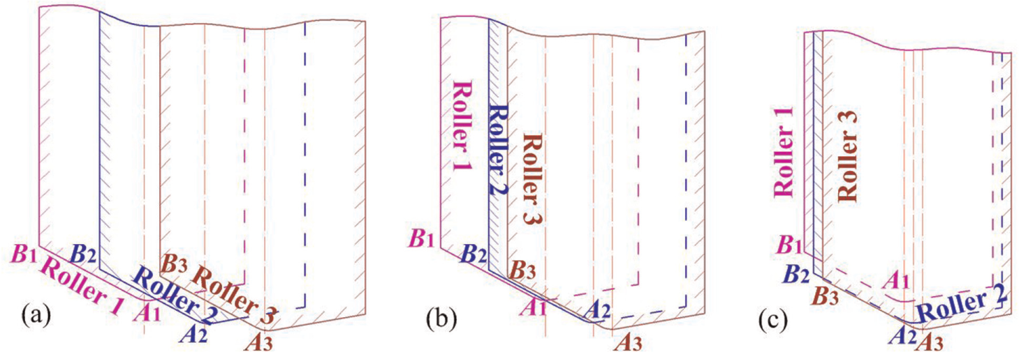
Position orders of rollers of (a) trial 5 (normal condition), (b) critical condition without position interference and (c) trial 1 (position interference condition).
It is clear that rear rollers will contact blank first and undertake wall thickness reduction that should be done by the front one, when condition of Figure 9(c) occurs.
Figure 10 shows stacked bar chart of distributions of the working stroke of rollers. Roller force remains 0 during unload stroke and fluctuates between 0 and larger value during transitional stroke. It can be seen from Figure 10(a) that the unload stroke accounts for quite visible scope of the whole stroke, compared with that in Figure 10(b). This means in most time of the stroke of rollers, some rollers remain unloaded while others remain overloaded due to position interference, which is contrary to the original intention of using three rollers in stagger spinning.
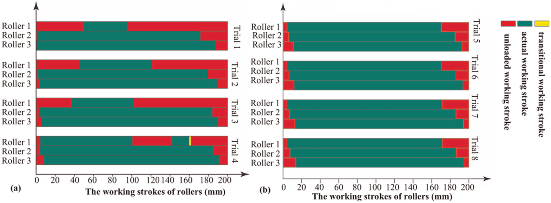
Working strokes of rollers: (a) group 1.1 with position interference and (b) group 1.2 without position interference.
Inclination interference
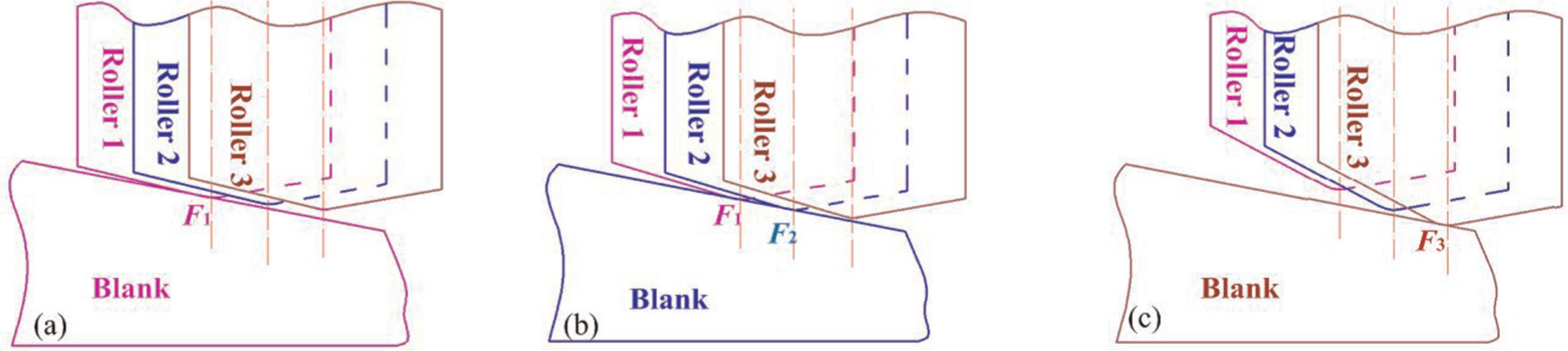
Inclination interference occurs when the first point in rollers that contact with the blank changes from front roller to rear roller, which is caused by inappropriate combination of attack angle of rollers and chamfer angle of blank, under conditions that position interference has been excluded.
Figure 11 shows the transition from normal stagger spinning without interference to the one with inclination interference. To facilitate understanding, position and dimension parameters of each roller are the same as those in group 2. It can be seen that the first point Fi (i = 1, 2, 3) in rollers that contact with the blank chamfer gradually changes from roller 1 (Figure 21(a)) to roller 3 (Figure 21(c)) with the decrease in chamfer angle of blank.
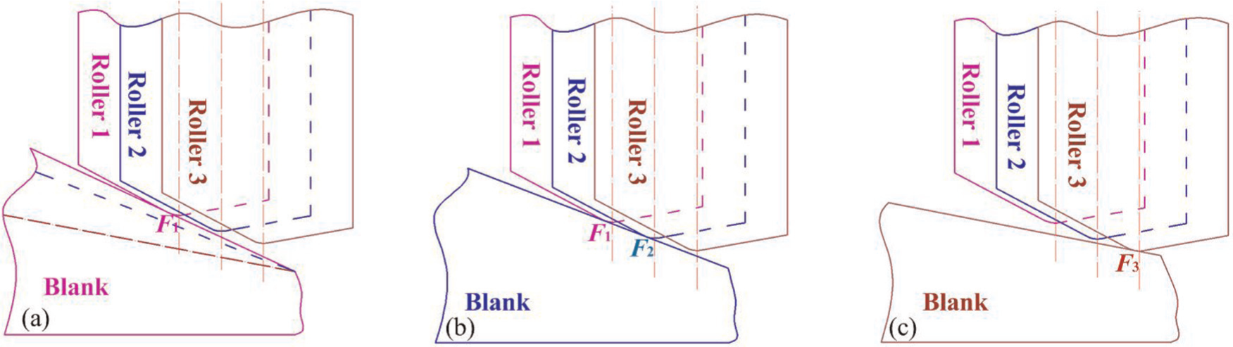
Transition of contact orders due to different chamfer angle of blank: (a) trial 13 (normal condition), (b) critical condition without inclination interference and (c) trial 9 (position interference condition).
It is clear that rear rollers will also undertake wall thickness reduction of the front one, when condition of Figure 11(c) occurs. Similar phenomenon occurs with the change in attack angle of rollers, as shown in Figure 12.
Transition of contact orders due to different chamfer angle of roller: (a) normal condition, (b) critical condition without inclination interference and (c) position interference condition.
Figure 13 shows distributions of working stroke of rollers in group 2. Compared with position interference, unloaded stroke of rollers caused by inclination interference is shorter. However, similar to position interference, inclination interference can also lead to local excessive roller force and oscillations of roller force, but with shorter durations and smaller fluctuations
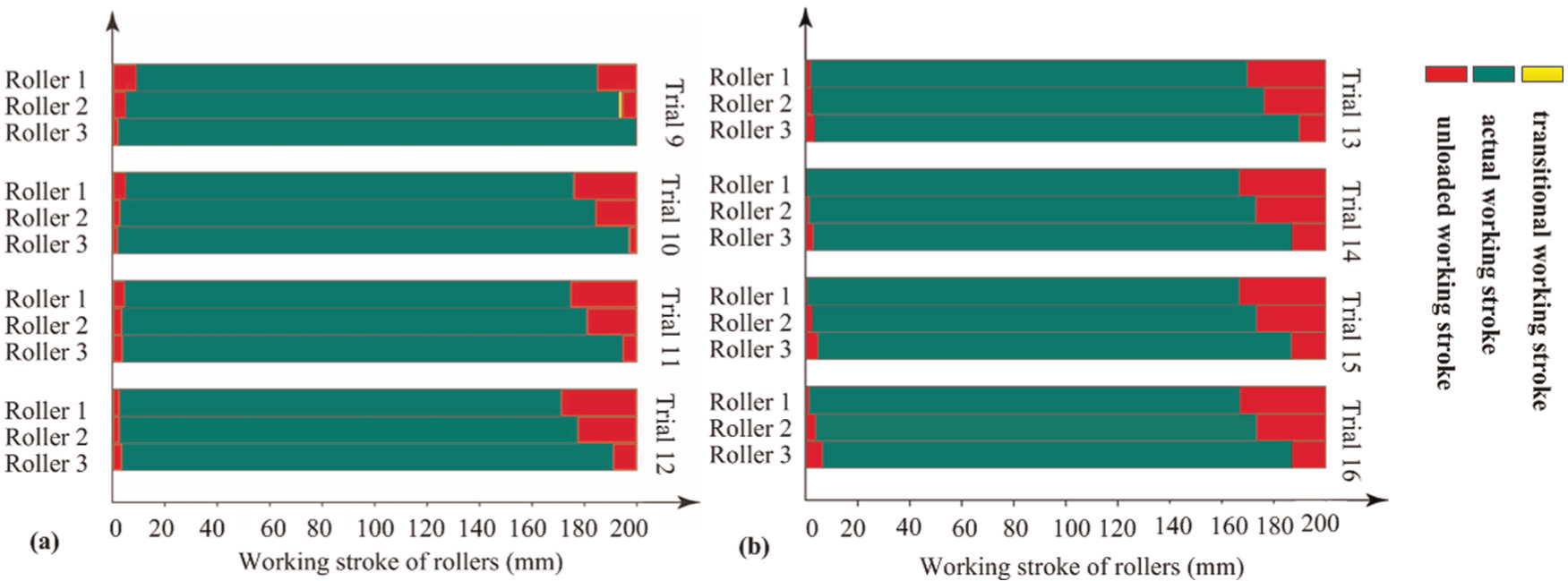
Working strokes of rollers: (a) group 2.1 with inclination interference and (b) group 2.2 without inclination interference.
Results and discussion
Influence of position interference
Oscillations of roller force
Figures 14 and 15 show variations in roller forces in group 1 within 25–40 s. Clear force oscillations of roller 2 can be observed, as shown in Figure 14(b), compared with those in Figure 15(b). It is noted that the time of the mutation range of rollers 2 and 3 is exactly the same, while force of roller 2 increases dramatically but that of roller 3 decreases sharply. In addition to the mutation area, it can be seen from Figure 14 that obvious oscillations appear in most time of the range. Oscillations of roller force have negative effects on dimensional and shape accuracy of products. Moreover, it can cause impact on spinning machine and short life of it.
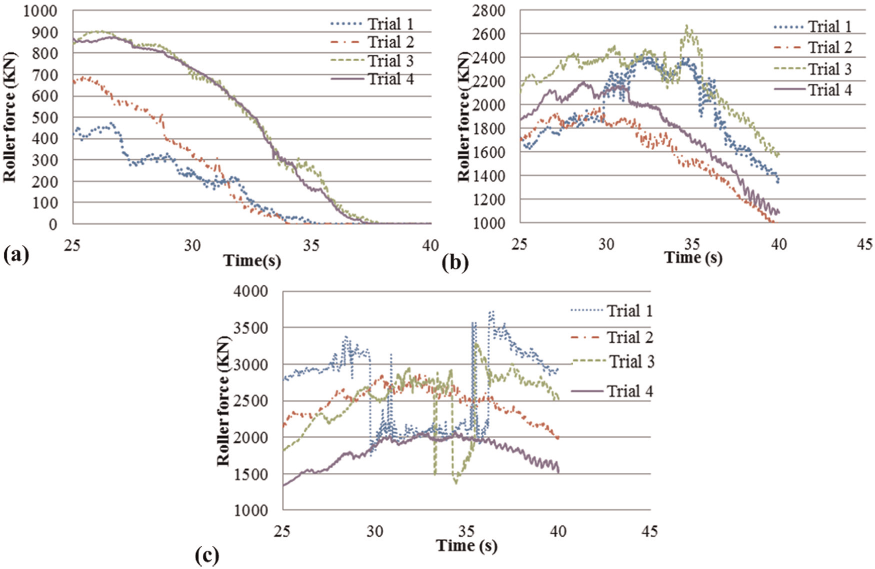
Oscillations of roller force in group 1.1: (a) roller 1, (b) roller 2 and (c) roller 3.
Roller force in group 1.2: (a) roller 1, (b) roller 2 and (c) roller 3.
Force component ratios of three rollers
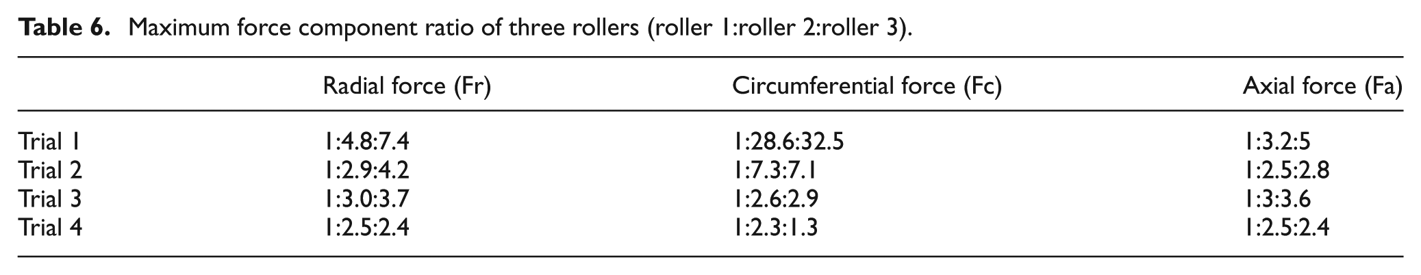
Table 6 presents force component ratios of three rollers in group 1.1. Figure 16 shows ratios of roller 1 to roller 2 in group 1. It is obvious that force components of rollers 2 and 3 in group 1.1 are much larger than those of roller 1, especially circumferential force component. For the good quality of stagger spinning products, forces of three rollers should be similar. However, compared with force in group 1.2, position interferences aggravate the unbalance of roller forces significantly. Moreover, excessive force of front rollers in the axial direction due to position interference will accelerate the damage of mechanical components of the spinning machine.
Maximum force component ratio of three rollers (roller 1:roller 2:roller 3).
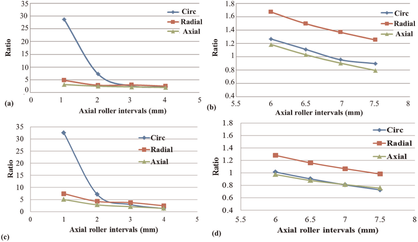
Force component ratios of roller 2:roller 1 in (a) group 1.1 and (b) group 1.2 and roller 3:roller 1 in (c) group 1.1 and (d) group 1.2.
Wall thickness variations
Figure 17 compares wall thickness variations of trials in group 1.1 and group 1.2 along the axial direction. Cross sections of each trial in group 1.1 are presented in Figure 18, straight lines in which are ideal generatrices of internal and external surfaces.
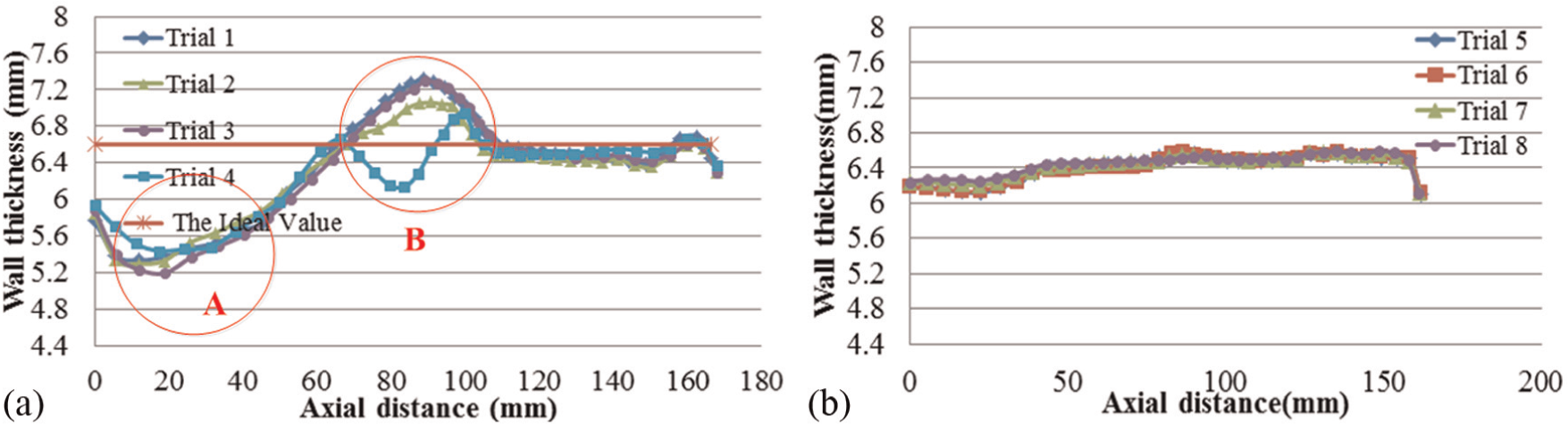
Wall thickness variations of trials in (a) group 1.1 and (b) group 1.2.
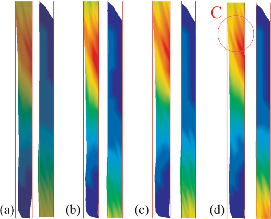
Cross sections of the concave and bulge parts of blank in (a) trial 1, (b) trial 2, (c) trial 3 and (d) trial 4.
As shown in Figure 17, wall thickness variations of each trial in group 1.1 have significant deviations from the ideal value, especially in area A and area B, compared with those in group 1.2. As shown in Figure 18, significant concave and bulge of external surface can also be seen in cross section of blank, corresponding to area A and area B. The additional wall thickness concave fluctuation in trial 4 is caused by local bulge of internal surface. As shown in Figure 18, internal surface of the blank which should contact with the mandrel has separated with it in area C. It is clear that the shape and dimensional accuracy of products will be affected by position interference as it can lead to significant bulge and concave defect in external and internal surfaces.
Strain variations in wall thinning
Figure 19 shows variations in radial and circumferential strains along the axial direction of group 1.1. Radial compressive strains play a prominent role during 60 mm from the beginning of the feed due to much higher values than the circumferential ones. The trends and values of axial strains are just contrary to those of radial ones, which is consistent with the deformation mechanism. It is noted that circumferential compressive strains rise quickly to peak value in the range of 60–80 mm, while radial compressive strains keep decreasing in trials 1–3. Circumferential compressive strains play a prominent role in this area, which is the main reason for the increase in the trends of wall thickness in this area. Circumferential strain of trial 4 in this range keeps decreasing without rising to the peak, which leads to the lower bulge than that in other trials, as shown in Figure 18.
Strain variations in group 1.1 along the axial direction: (a) radial, (b) circumferential and (c) axial.
Influence of inclination interference
High probability of occurrence of inclination interference
The chamfer angle of blank is usually designed equal to the forming angle of the first roller. However, combination of rollers with different forming angle is widely used in stagger spinning, which means inclination interference also has high probability to occur due to the combination of attack angle of rear rollers and chamfer angle of blank. In addition, under conditions to form the blank designed with special bevel angle, the forming angle of all three rollers may have to be larger than that of chamfer angle of blank in order to ensure the forming quality as chamfer angle of blank may be quite small under this condition. Interference phenomenon can also happen.
As can be seen from the above, inclination interference has quite high probability to occur in both FE analysis and actual production. Few have pursued studies on it and make its influence clear as inclination interference is quite subtle and more easier to be overlooked. So, it is important to propose this phenomenon and define it exactly. It is also necessary to separate inclination interference from the result to make its influence clear.
Selection of the appropriate research method
There are three equivalent methods to separate the influence of inclination interference: (1) ensure the chamfer angle of blank is constant, change the forming angle of roller; (2) ensure the forming angle of roller is constant, change the chamfer angle of blank and (3) change the chamfer angle of blank and forming angle of blank together.
It is widely acknowledged that the change in forming angle of rollers has quite great influence on the forming result. This means that it will be too hard to separate the influence of inclination interference if method (1) is used due to the high coupling between the change in forming angle and inclination interference. The chamfer of blank is the only changing parameter that may disturb the result of inclination interference in method (2). Obviously, compared with methods (1) and (3), method (2) is the most operable and effective method to separate the influence of inclination interference as the influence of the chamfer angle of blank is easy to get.
Influence of chamfer angle
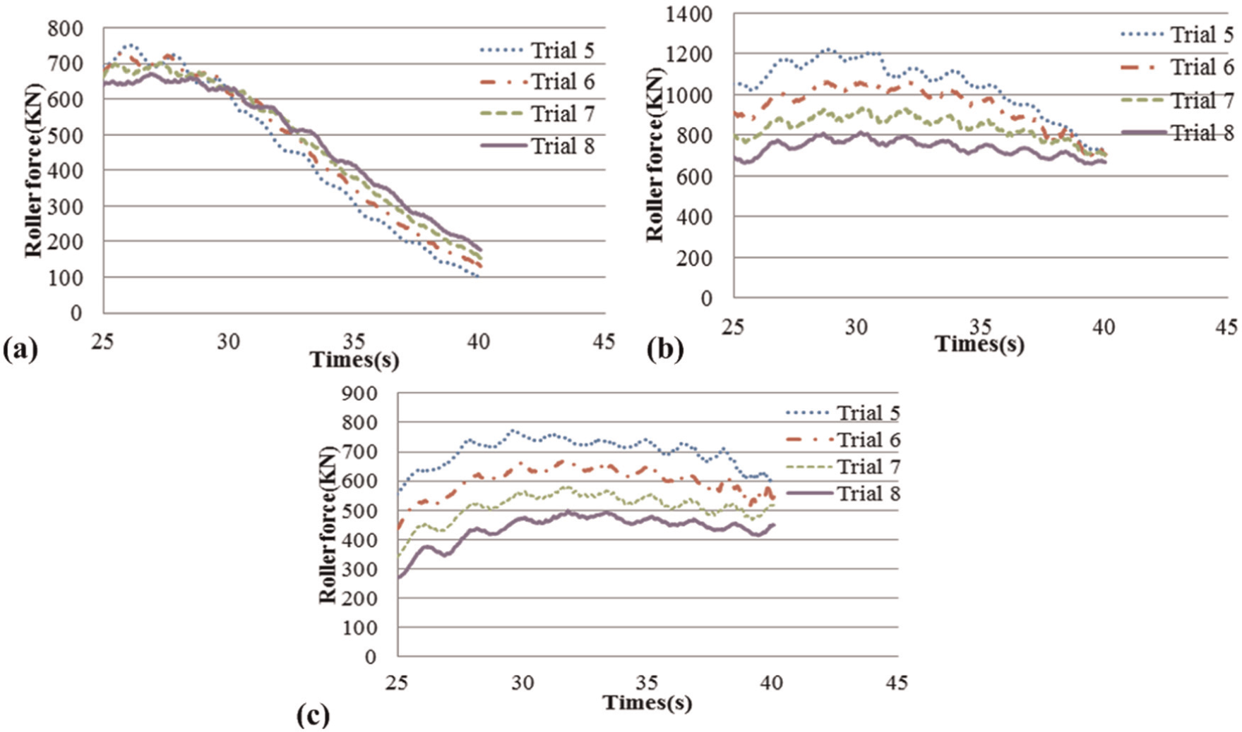
The blank of each trial in group 2 has different chamfer angle. Therefore, it is necessary to figure out the influence of chamfer angle to investigate the influence of inclination interference. Figure 20(b) shows the maximum roller force in group 2.2. Errors of roller force between trial 15 and other trials are shown in Table 7. The change in roller force is quite small with the increase in chamfer angle as can be seen from Figure 20(b) and Table 7. The influence of chamfer angle on roller force is little.
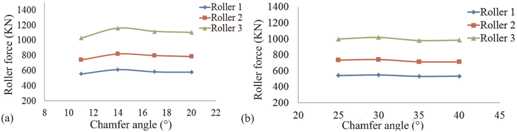
Variations in roller force changing with chamfer angle: (a) group 2.1 and (b) group 2.2.
Errors of roller force in group 2.2.
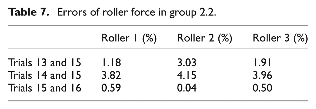
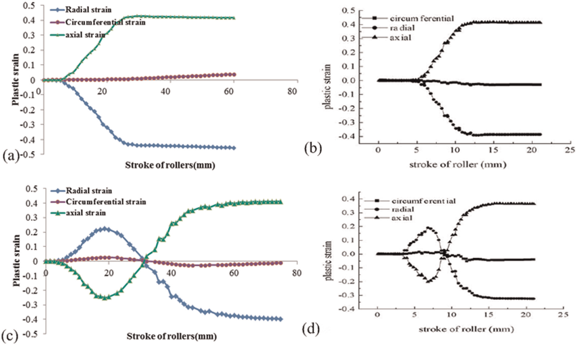
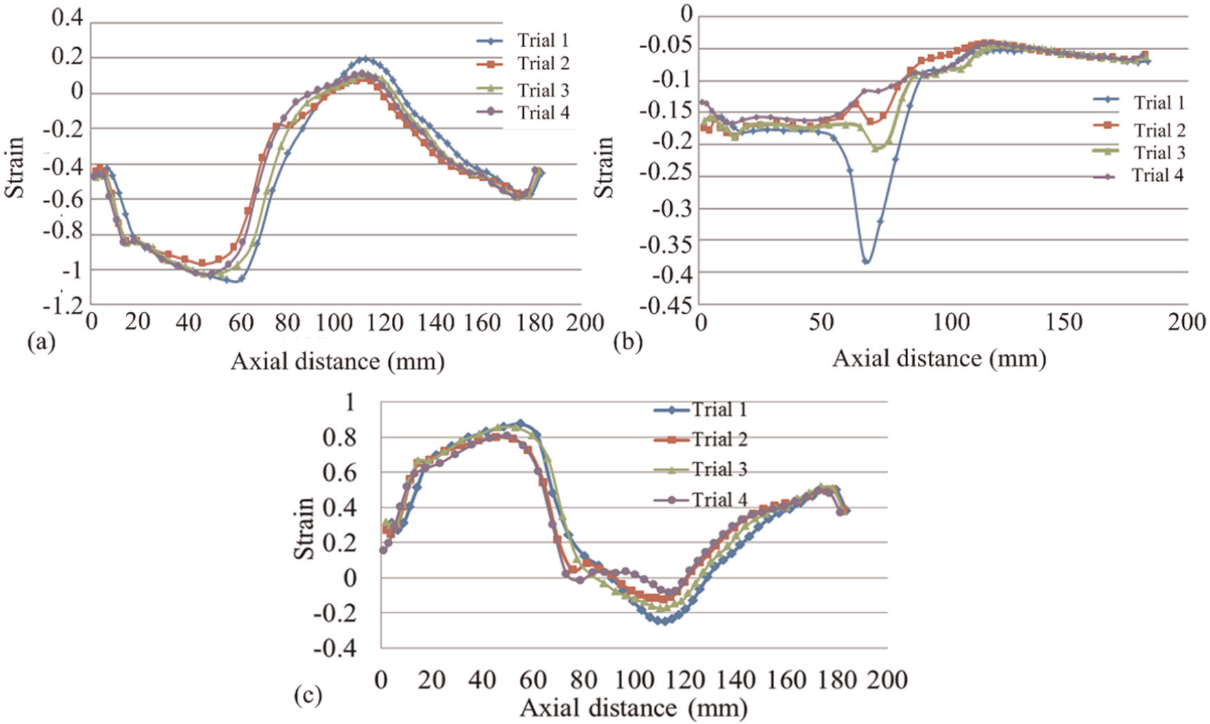
Figure 21 compares variations in radial, circumferential and axial strains of trials 14 and 15 under a local cylindrical coordinate system, after feeding 100 mm. It can be seen from Figure 21 that variations in strains of the two trials are almost the same both in internal and in external surfaces. Strain values of the two trials vary little. Similar results are found in trials 13 and 16, in which the errors between trial 15 are smaller.
Strain variations of trials 14 and 15: (a) radial, (b) circumferential and (c) axial strains of trial 14; (d) radial, (e) circumferential and (f) axial strains of trial 15.
Figure 22(b) shows stress variations of trials in group 2.2 along the axial direction. There are little differences between each trial. Hysteresis in the axial direction is due to length difference in blank caused by the different chamfer angle. The highest error of average stress exists between trials 14 and 15, 2.6%. It is clear that the influence of chamfer angle on stress is little. The influence of chamfer angle on wall thickness variations of trials in group 2.2 is shown in Figure 23(b). It can be seen that thickness values of each trial are almost the same. Chamfer angle has no obvious influence on wall thickness variations.
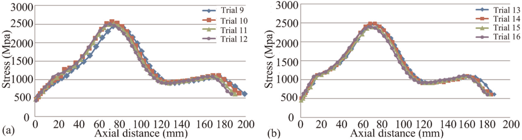
Stress variations in (a) group 2.1 and (b) group 2.2.
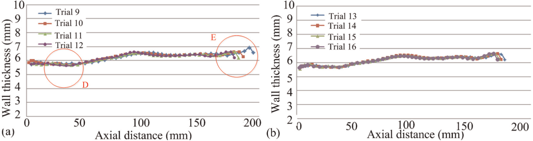
Wall thickness variations in (a) group 2.1 and (b) group 2.2 along the axial direction.
As can be seen from the above, chamfer angle has no significant influence on roller force, wall thickness, stress and strains under conditions without interference. Based on this, the influence of inclination interference has been investigated.
Maximum roller force
Figure 20(a) shows the effects of inclination interference on maximum roller force. The maximum error is 6.86% in roller 3 between trials 9 and 11. Trends of roller forces in group 2.1 and group 2.2 are basically the same. Errors between roller forces in group 2.1 are still small, while a little larger than those in group 2.2. It can be seen that except the beginning and ending areas, inclination interference has no significant influence on the maximum roller forces.
Stress variations in blank
Figure 22(a) shows stress variations of trials in group 2.1 along the axial direction. As can be seen from Figure 22, both trends and values of the two groups are similar, except hysteresis in the axial direction caused by the chamfer. The highest error is 5.01% between trials 9 and 11. Errors of other trials are 3.81% between trials 10 and 11 and 1.43% between trials 12 and 11.
Strain variations in blank
Figure 24 shows variations in strain of trials 10 and 14. Strain distributions of the two trials are similar except at the beginning areas of the blank. Compared with trial 14, trial 10 has higher compressive strain in beginning areas. There are more transitions between different values. It is noted that annular radial compressive strains and axial tensile strains have visible differences in areas where the highest compressive strains are located. As shown in Figure 24, highest compressive strain in trial 10 shows irregular distribution. High local strain also occurs discretely. The strains are inconsistent in circumferential direction, compared with trial 14, in which radial and axial strains have formed an annular region. Similar results of circumferential strains can be observed near the end areas of blank.
Strain variations of trials 10 and 14: (a) radial, (b) circumferential and (c) axial strains of trial 10; (d) radial, (e) circumferential and (f) axial strains of trial 14.
Wall thickness variations
Figure 23(a) shows variations in wall thickness in group 2.1 along the axial direction. Deviations in wall thickness are little except in areas D and E, compared with those in group 2.2. Area D locates in the beginning parts of the blank, which are the most concentrated areas of inclination interference. Area E is close to the end of the blank, where the force oscillations occur. Figure 25 shows partial enlargement of areas D and E. It can be seen that wall thickness of each trial is in a kind of waviness shape in area D. Visible fluctuations occur at the end of the blank.
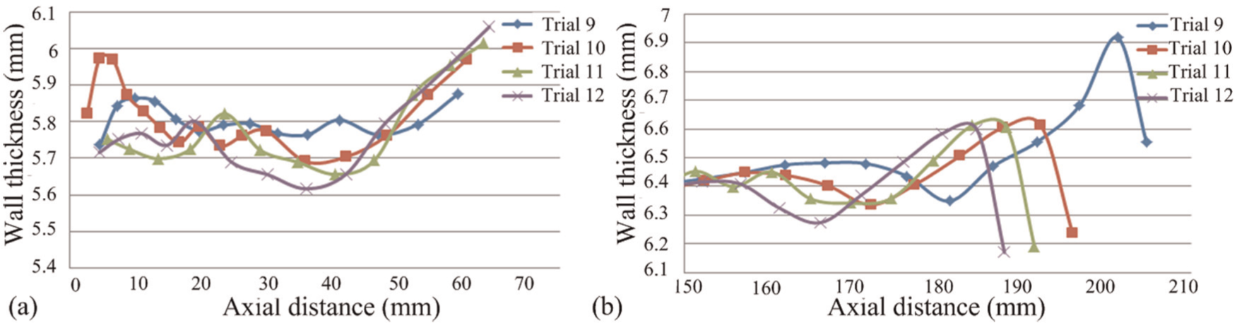
Partial enlargement of areas (a) D and (b) E.
Inclination interference will lead to fluctuations in the beginning and ending areas of blank. Although the affected areas account for only relatively small proportions of total, overall dimensional accuracy and shape accuracy are affected.
Derivation of formulae to avoid interference
Derivation for formulae of intervals without position interference
As can be seen from the above, position interference will reduce the quality of products and cause an impact on spinning machine. The efficacy of the current method for interval selection is quite limited, which cannot meet the requirements of the complex boundary conditions of roller combinations nowadays. Position interference is often found in designed trials of studies that concentrate on obtaining suitable roller intervals. Few have pursued studies on it and proposed effective workaround. This article provides the derivation processes for formulae of roller interval selection, which can effectively avoid the position interference. Scientific computing software Mathematica is used in the process of calculation.
1. Figure 26 shows the principle diagram of stagger spinning without position interference under conditions
To avoid position interference, the lowest point Ai (i = 1, 2, 3) of the top arc of front roller should be outside the scope of rear roller. Critical condition is that
It is easy to get the following relationship
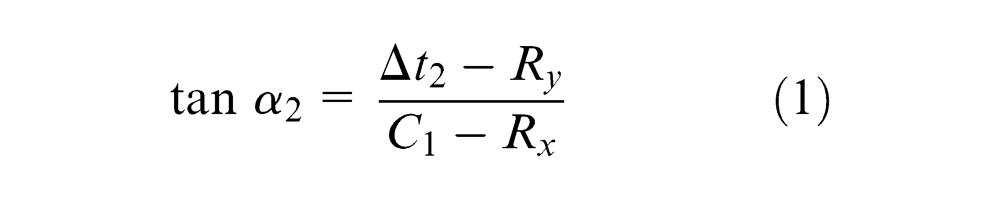
The critical condition under conditions
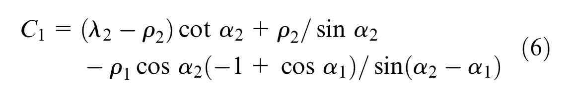
where
Substituting
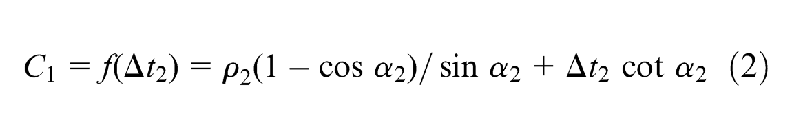
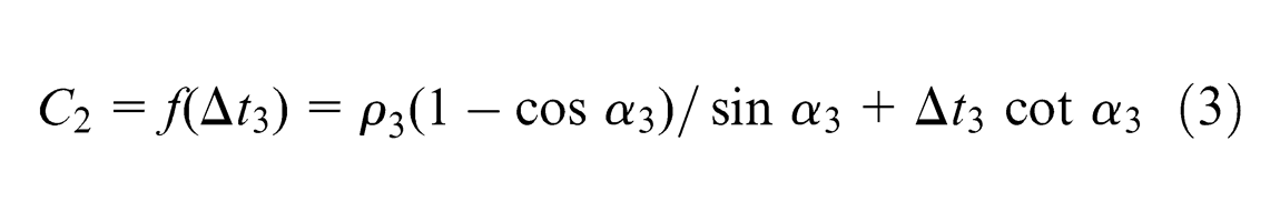
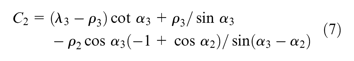
Similarly, the relationship between radial and axial intervals of rollers 2 and 3 can be derived as
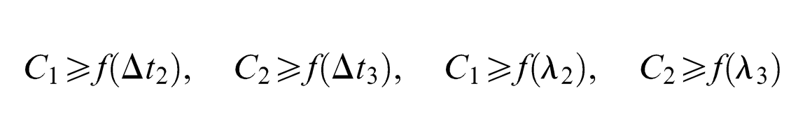
In order to avoid interference, the relationships of radial and axial intervals in this case should satisfy

2. Figure 27 shows the principle diagram of stagger spinning without position interference under conditions
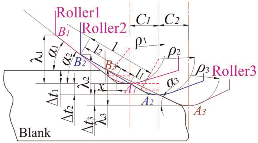
Critical condition under conditions
To avoid position interference, lowest point Ai of the top arc of front roller should be outside the scope of rear roller. Meanwhile, endpoint Bi of the attack chamfer of rear roller should be inside the scope of front roller. Critical condition is that AiBi is just over Ai. Meanwhile, Bi+ 1 locates on AiBi.
To make sure that Ai will not enter the scope of rear roller, assume that the relationship between

To make sure that Bi stays inside the scope of front roller, assume that the relationship between

The following relationship can be obtained
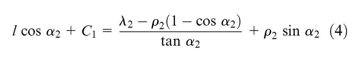
among which

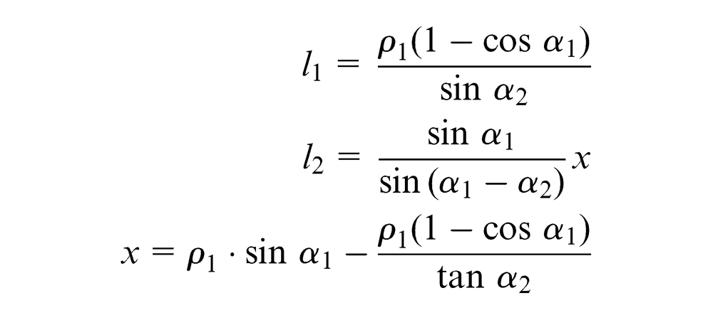
Substituting x into l
1, then substituting
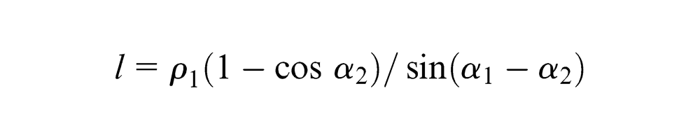
Substituting
Similarly, the relationship between radial and axial intervals of rollers 2 and 3 can be derived as
In order to avoid interference, the relationships of radial and axial intervals in this case should satisfy
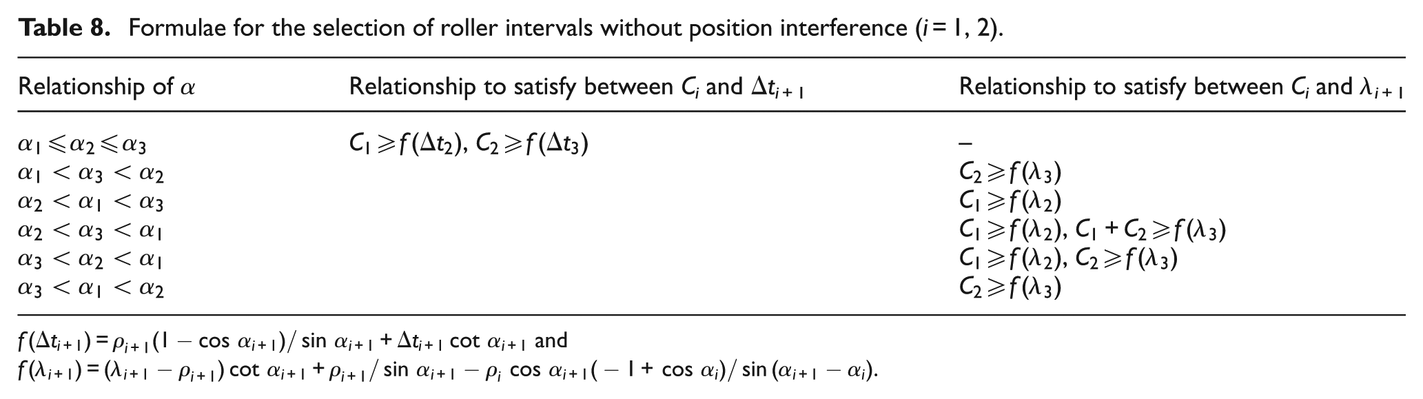
Derivations of other cases are similar to the above. Formulae to avoid position interference are listed in Table 8. After preliminary selection of roller intervals within empirical values, formulae in Table 8 should be selected to get the range of roller intervals without position interference, which will reduce the amount of invalid experiment or simulations.
Formulae for the selection of roller intervals without position interference (i = 1, 2).
Derivation for formulae of intervals without inclination interference
After ensuring that there is no position interference, inclination interference should also be avoided due to the high possibility of occurrence and the negative effects that cannot be overlooked. Derivation processes for formulae of roller intervals to avoid inclination interference are given, with rollers 1 and 2 as example.
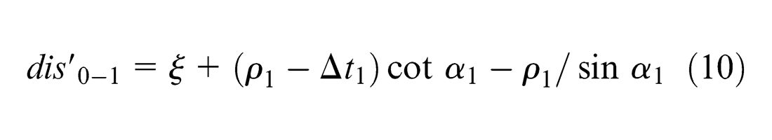
To make sure roller 1 contacts with blank first, minimum axial distance dis
1 between roller 1 and blank should be less than that of roller 2. It is clear that first contact point in rollers locates on top fillet AiDi under condition
To get minimum axial distance, a Cartesian coordinate system is established with the center of the arc of roller 1 as the origin of coordinate, as shown in Figure 28.
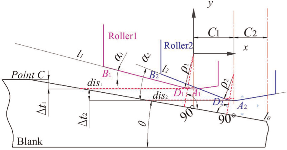
Distance between rollers and blank.
Assuming that the abscissa for point C of blank is

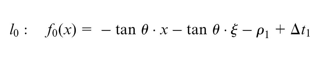
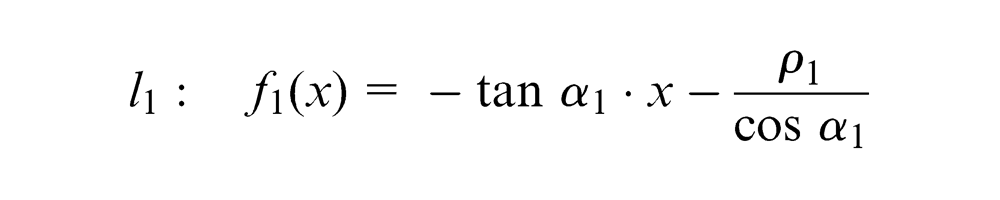
It is easy to obtain equation of straight line
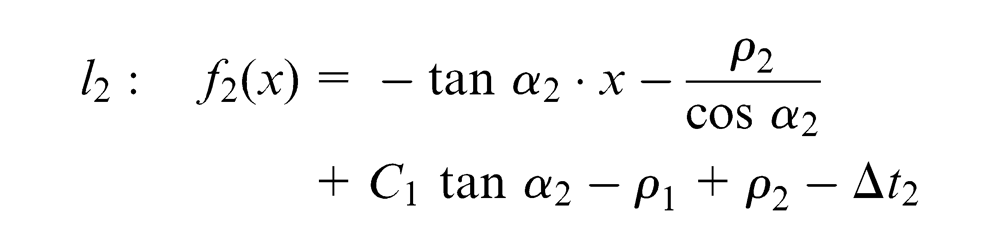
Equation of straight line
Equation of straight line
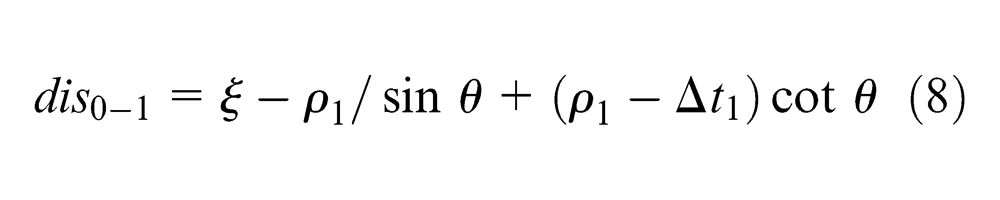
1. When the first point in rollers contacts with the blank located on AiDi, coordinates of the point in roller 1 are

Substituting
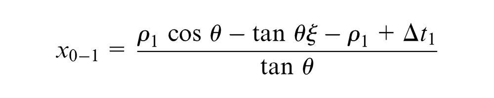
The axial distance between the first contact point in roller 1 and blank is
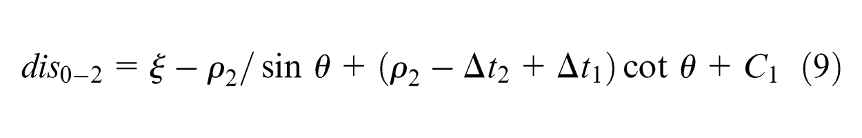
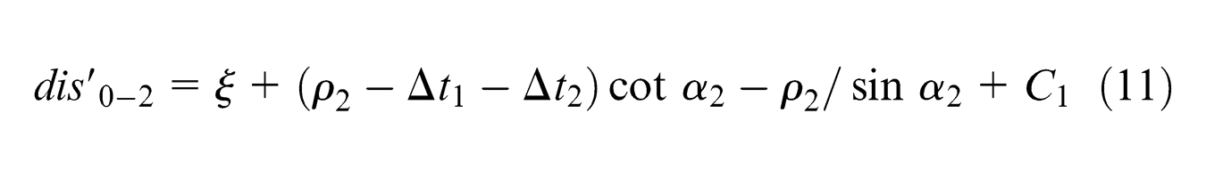
Similarly, the axial distance between the first contact point in roller 2 and blank is
2. When the first point in rollers contacts with the blank located on BiDi, substituting
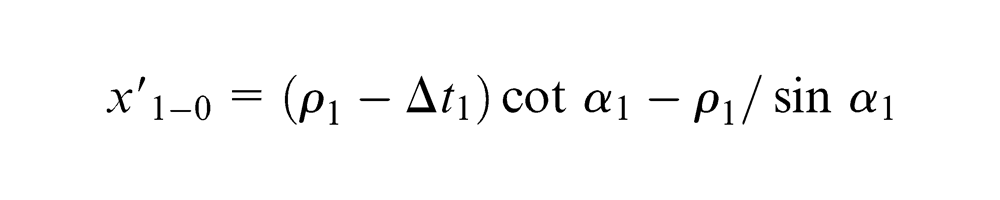
The axial distance between the first contact point in roller 1 and the blank is
Similarly, the axial distance between the first contact point in roller 2 and the blank is
The derivations for rollers 2 and 3 are similar to the above. Formulae to avoid inclination interference are listed in Table 9.
Formulae to avoid inclination interference (i = 1, 2)
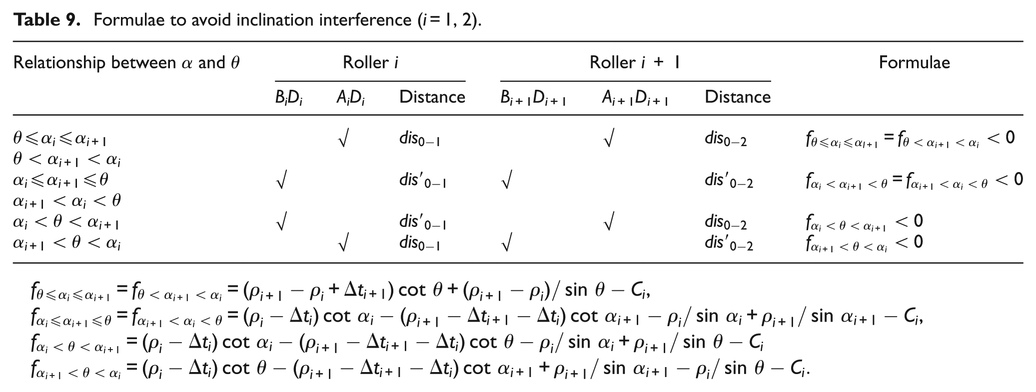
Compared with position interference, inclination interference is more subtle and more easier to be overlooked. However, it also has negative effects on the quality of products. After obtaining the range of intervals without position interferences, formulae in Table 9 should be used to avoid inclination interference. When chamfer angles are changed or rollers with different dimensional parameters are replaced, verification should be conducted again.
Verification of the formulae
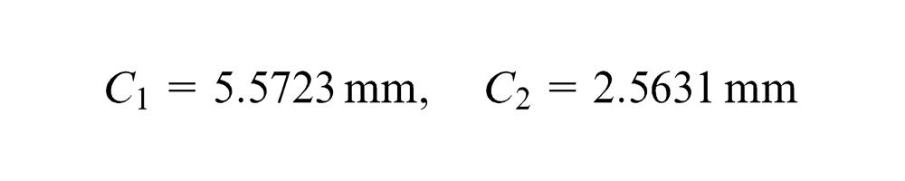
From Table 8, we can get formulae to avoid position interference under conditions
By substituting
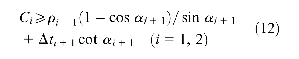
Similarly, from Table 9, we can get simplified formulae to avoid inclination interference under conditions
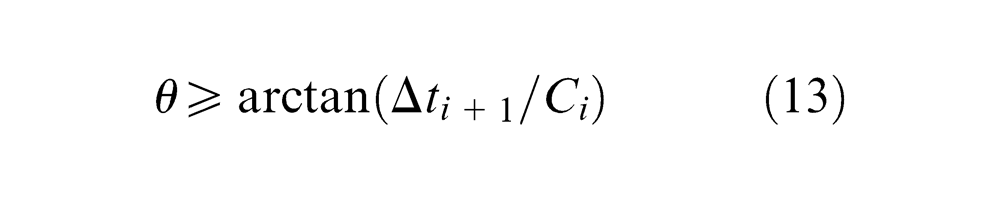
By substituting C 1 = C 2 = 4.5, Δt 2 = 1.7 and Δt 3 = 1.3 into equation (13), we can get the minimum value of the angle of blank chamfer in group 2 without inclination interference

It can be seen that the calculated values match the measured values exactly, as shown in Figure 29.
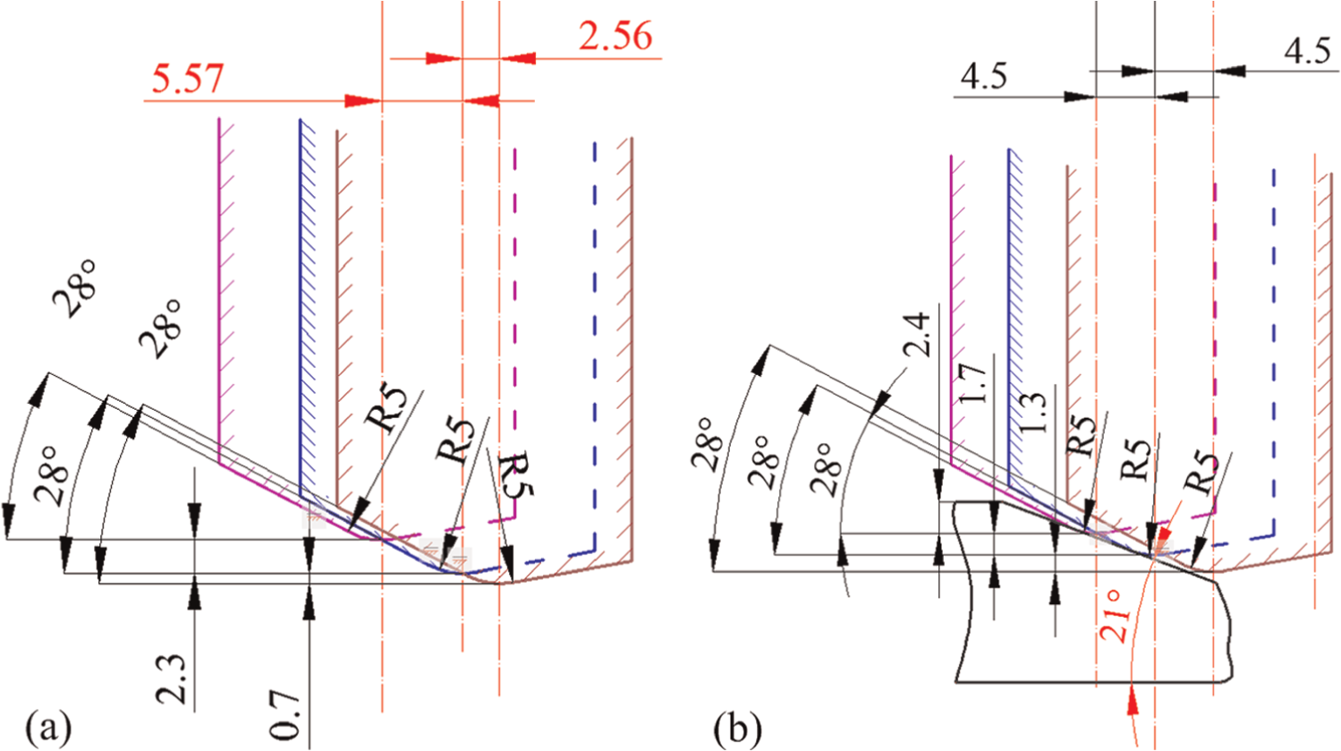
Critical conditions of (a) group 1 and (b) group 2.
Conclusion
Two kinds of interference phenomenon, position and inclination interference, are characterized and investigated in this article according to the cause and characteristics. Position interference is caused by inappropriate combination of axial and radial intervals, while inclination interference is due to inappropriate attack angle of rollers and chamfer angle of blanks.
Position interference has significant negative effects on the balance and stability of roller force. So, the shape and dimensional accuracy of blank as position interference have resulted in significant bulge and concave of wall thickness.
Inclination interference has little effects during most time of the stagger spinning process. However, similar phenomenon to that of position interference can be observed in the beginning and ending areas, while the duration is much shorter and the amplitude is smaller.
Formulae to avoid interference phenomenon are derived. Formulae for position interference can help exclude invalid combination of roller intervals (C and Δt)), while formulae for inclination interference can guide the selection of inclination of roller and blank. The presence of large amounts of invalid parameter setting in this study of stagger spinning can be effectively prevented.
Footnotes
Declaration of conflicting interests
The authors declare that there is no conflict of interest.
Funding
We would like to thank the specialized Research Fund for the Doctoral Program of Higher Education (No. 20120101130003), the Key Project of Science and Technology Program of Zhejiang Province (No. 2013C01135), the Youth Fund Project of the State Key Lab of Fluid Power Transmission and Control, Zhejiang University (No. SKLoFP_QN_1301) and the teacher professional development project of the college visiting scholar (No. FX2012084).