
Abstract
In this article, Al5083 and pure copper plates were connected by friction stir welding in butt position. The effects of tool rotation speed on mechanical properties and microstructure of the joint have been investigated experimentally. A joint that was formed at the rotation speed of 800 r/min and tool transverse speed of 40 mm/min had the highest tensile strength, about 96% of the weak base metal strength. Joint strength at high speeds was due to formation of intermetallic compounds, and it increased the probability of defect formation, and reduced and conversely increased the strength at low rotation speeds by increasing the material mixing and formation of metal matrix composite. Microstructural examination revealed that the intermetallic compounds formed during processing and Al4Cu9 and Al2Cu were detected by X-ray diffraction analysis in the stir zone as intermetallic compounds. Formation of intermetallic compounds increased with increase in the rotation speed. The fracture surface showed that the fracture starts from the interface and brittle failure occurs.
Introduction
Connecting copper and aluminum by using a fusion welding method creates covalent bonds at the interface, which reduces the weld strength and electrical conductivity in this region. Increasing the input heat leads to enlargement of the heat-affected zone, which decreases the joint strength. 1 In conventional fusion welding methods, the minimum strength is observed in the heat-affected zone. To resolve this problem, solid-state welding method is used. Friction stir welding (FSW) is a thermomechanical solid-state welding method, using which almost all metals are connected, especially dissimilar metals. It is a perfect method for welding of low-fusion weldable materials that are hard to join by conventional fusion welding methods. Unlike most conventional welding methods, joining by FSW is performed in the solid-state with no melting. In this method, because of limiting of the zone affected by heat, dynamic recrystallization and fine grains in the microstructure, mechanical properties of the joint is often improved. However, for materials with high thermal conductivity and melting temperature, such as copper, to obtain a perfect weld is very difficult because of low heat generated by friction and deformation to soften material around the pin. Copper and aluminum are incompatible metals due to higher affinity at temperatures higher than 120 °C and produce brittle intermetallics on the interfaces. 2
The friction welding method has been used to connect all aluminum alloys and copper. The microstructure evolutions and studying the effects of welding parameter,3,4 optimizing the process parameters to obtain a sound joint with the maximum strength 5 and simulation of the FSW process6,7 have been widely studied for copper and all aluminum alloy components. This method is also used to connect different types of aluminum alloys, and all aspects of the process have been studied in detail.8,9 Lee and Jung 10 investigated the weldability of copper by FSW, and for the first time, they were able to achieve a perfect joint with tensile strength of approximately 89% of the base metal.
FSW method is being used currently to connect copper to aluminum due to various advantages of this method. Dissimilar FSW of copper–aluminum lap joint has been studied, but fewer investigations have been done on butt joints. Abdollah-Zadeh et al. 11 experimentally studied lap joints of copper–aluminum plates that had been welded by FSW method. The microstructure changes during process, tensile strength of the joint and the hardness profile of the welding section of the joint were discussed by Abdollah-Zadeh et al. Firouzdor and Kou 12 modified the copper–aluminum lap joint by changing the position of the plates, and improved the tensile strength of it. They studied microstructure and mechanical properties of modified joint and compared them to the traditional joints. Bisadi et al. 13 studied lap joints of pure copper to 5083 aluminum alloy. They experimentally investigated the effects of FSW parameters, rotation speed and welding speed on the microstructure and mechanical properties of the joint. Ouyang et al. 2 investigated the microstructure changes during butt FSW of copper and Al6061. They also measured the temperature distribution in the plate and studied microstructure of the joint by optical microscope (OM) and X-ray diffraction (XRD) to identify the intermetallic compounds that formed during the process. Liu et al., 14 by tensile test, XRD and OM, studied the mechanical properties and microstructure of the copper–aluminum welded joints. In their study, the effect of process parameters on the microstructure was not examined, and only the mechanical properties were optimized in terms of rotational and welding speed. Mechanical properties and microstructure of copper–Al1060 joint welded by FSW were studied by Xue et al. 15 They focused on the microstructure and defects forming on the weld nugget zone. In another study, Xue et al. 16 studied the interface of the copper–Al1060 joint welded by FSW and determined the formation of intermetallic compounds in the interface. Galvão et al., 17 by using two different tools, studied the effect of the shoulder geometry on forming and distribution of intermetallic compounds in FSW of copper–aluminum butt joint. Tan et al. 18 studied the Al–Cu interface layer and intermetallic compounds formed during the process of butt Al–Cu joints welded by FSW.
Previous researches have shown that many parameters such as tool rotation speed, welding speed and offset of the tool affect the quality of the dissimilar FSW joints. Until now, few studies have been focused on dissimilar FSW copper–aluminum butt joint, and many aspects of the process are still unknown and further investigations are needed. Thus, the studying of the effect of FSW parameters on the microstructure and the mechanical properties of dissimilar copper–aluminum joint seem to be worthwhile. In this article, dissimilar FSW Al5083–copper butt joints have been studied and effects of tool rotation speed on the quality of the welded joint have been considered. The aim of this study was clarification of the effect of tool rotation speed on the mechanical properties and the microstructure in butt dissimilar Al5083–copper FSW joints.
Experimental procedure
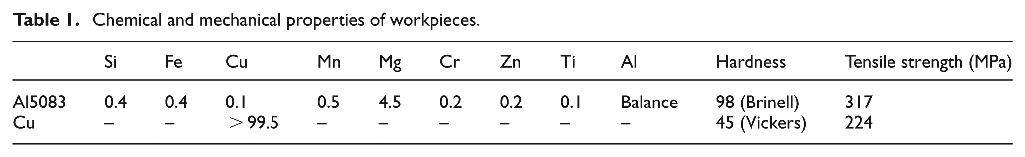
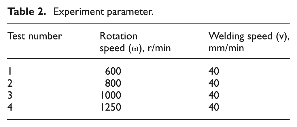
Al5083 plates 5 mm thick, 200 mm in length and 100 mm in width and commercially pure copper were butt-welded in this study. The chemical composition and mechanical properties of the used materials are given in Table 1. The edges and surfaces of the plates were cleaned to remove the oxides and pollutions. A vertical mill that could have automatic vertical and horizontal movement was used in the process. Tests were conducted at a constant tool traverse speed of 40 mm/min, and rotation rate was considered in the range of 600-1250 r/min. All the FSW conditions of the specimens are shown in Table 2.
Chemical and mechanical properties of workpieces.
Experiment parameter.
The tool was cylindrical, made of tool steel H13 and heat treated to increase strength and hardness. The tool shoulder was concave with 6° concavity and 20 mm in diameter. The pin was simple, cylindrical and non-threaded, 5 mm in diameter and 4.7 mm in length. The tool had 3° tilt angle for better performance. To prevent lateral movement and bending of the plates during welding, a fixture was designed and built. The fixture and tool geometries are shown in Figure 1(a) and (b).
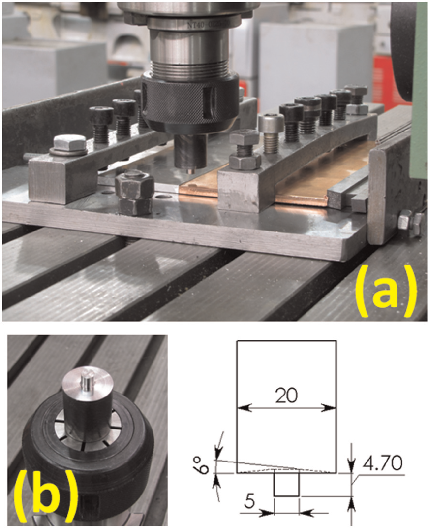
(a) A picture of used fixture and (b) tool and schematic geometry of the tool.
After welding, cross sections of the weld were prepared by using usual preparing microstructural methods, including cutting, grinding and polishing for metallographical analysis. The Poulton’s reagent solution was used for etching aluminum and another solution (60% H2O and 40% HNO3) used for copper. After etching, OM was used to observe the microstructure of the welded joints. Microstructure characterization and analyses were performed by scanning electron microscopy (SEM), energy dispersive spectroscopy (EDS) and XRD.
After initial assessment, samples with no defects were prepared for tensile test and tested. To evaluate the strength of the joint, tensile test was done. Tensile specimens according to ASTM-E8M and by using water jet were cut from welded plates. The cuttings were made perpendicular to the weld line, and the joint was in the middle of the tensile specimens. The standard dimensions of tensile specimens and a prepared sample are shown in Figure 2. All tensile tests were performed by using a constant pulling speed of 2 mm/min with SANTAM STM-250 machine. Each test was repeated three times, and the maximum tensile load and position of failure were recorded for each sample.
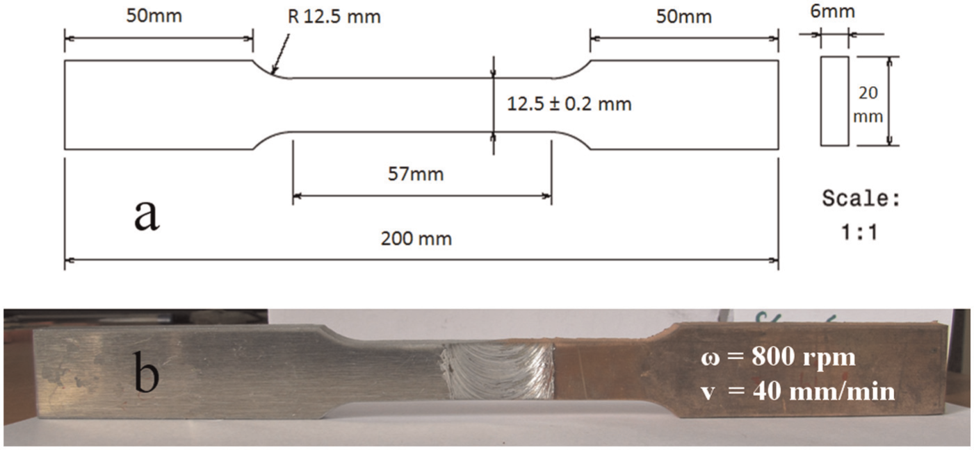
(a) Standard tensile specimen and (b) prepared sample from welded plates.
Results and discussion
The surfaces of the welded specimens are shown in Figure 3. At rotation speed of 600 r/min, surface was coarse and rough. Lack of the proper flow of material due to the low ductility caused the rough surface of the sample. There were particles that looked like chips on the surface of specimen conducted at rotation speed of 600 r/min, and it seemed that these particles were scraped from the surface and the weld flashes were thin with sharp edges. At low speeds, the generated heat was not enough to soften the material. So when the shoulder contact with workpiece surface, what happens is look like to chip removal operations that results the rough surface. By increasing the rotation speed (especially for speeds greater than 1000 r/min), the flash was increased. The specimens which were conducted at 1000 and 1250 r/min had rough surfaces and significant flashes as well. The flashes were thick and almost had no sharp edge. The pasty material, which was pushed out of the weld zone, due to rotation and transverse moving of the tool, was formed by these flashes. At high rotation speeds, due to increasing temperature, the condition of the contact area of the tool-workpiece changes into stick that the form of flashes and surface quality indicate the presence of these conditions.
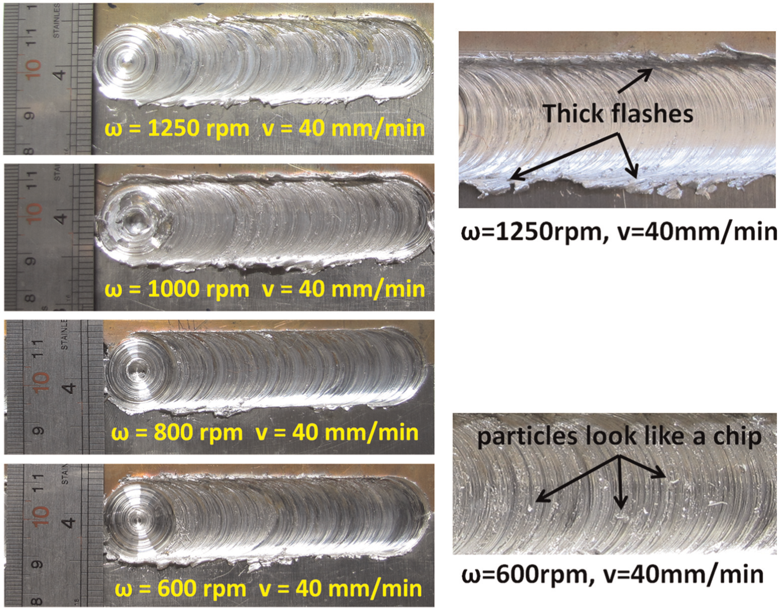
Surface quality of welded specimens.
The specimen conducted at a rotation speed of 800 r/min had better quality than the others. The surface was smooth, and little flash was observed. In the contact area, at low temperatures, slip conditions and at high temperatures sticky condition are dominant. Both of these conditions reduce the quality. However, there is a middle situation that there is a combination of slip and stick on the contact surface. In this case, each of the conditions is satisfied instantaneously, and these conditions are constantly changing. Appropriate quality of the surface can be determined from these conditions.
The cross sections of the welded joints are shown in Figure 4 and give information on mixing materials. At low rotation speed, especially 600 r/min, mixing materials along interface was approximately uniform and more copper entered the aluminum side. But at high rotation speeds, especially 1250 r/min, the material was mixed at the interface and copper significantly entered the aluminum matrix only in the upper part of the joint due to the effects of the shoulder. There were no defects at cross sections in visual inspection.
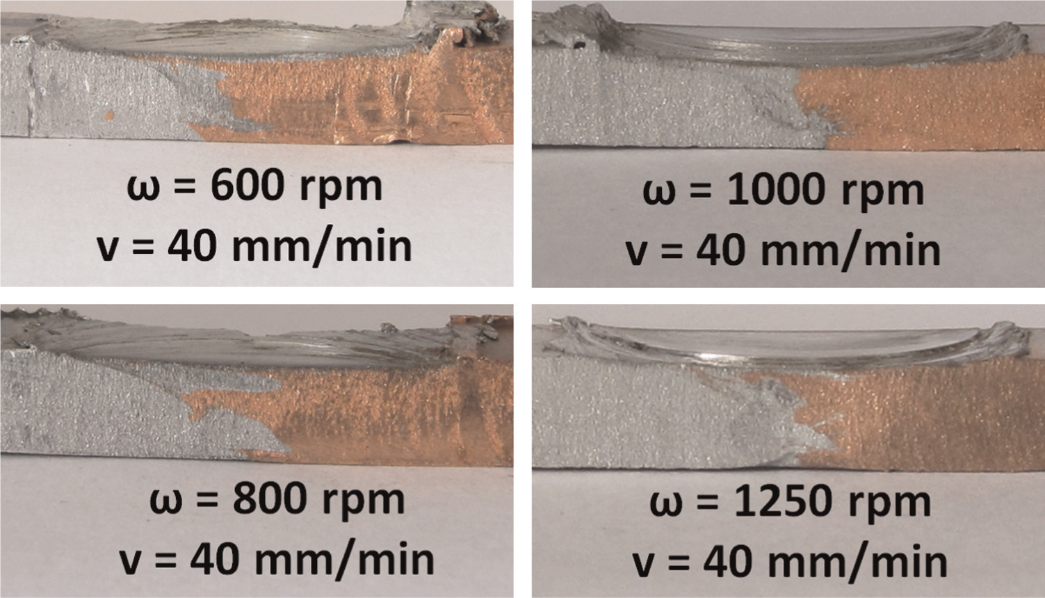
The cross section of the welded specimens.
In the middle of the cross section, called stir zone, softened materials are mixed together by both rotational and longitudinal motion of the pin to perform the connection process. In this area, materials are deformed severely by the rotating motion of the pin and mechanically mixed. A layer structure was observed at the interface of Al–Cu (Figure 5(a)) at rotation speed of 600 r/min, which is formed by mechanical mixing of copper and aluminum. At layer structure, layers of copper are surrounded by a dark matrix. The rotation speed of the tool had the opposite effect on the volume of layer structure, and by increasing the tool rotation speed, the layered structure is reduced. Layered structure faded when the rotation speed was increased, and at 800 r/min, there was no copper layer and just elongated particles of copper were observed (Figure 5(b)). At high rotation speeds, more than 1000 r/min (Figure 5(c)), layered structure was not observed. The layered structure faded due to rising temperature at higher speeds, which causes more softening of the material and more uniform mixing.
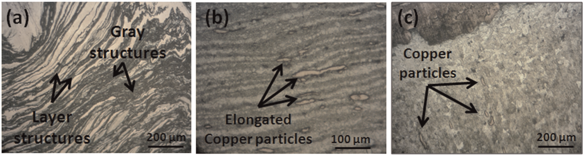
Magnified view of the cross sections: (a) layered structure at specimen conducted at 600 r/min, (b) elongated copper particles at specimen conducted at 800 r/min and (c) copper particles spread in the interface at specimen conducted at 1000 r/min.
The particles with different sizes and shapes were dispersed randomly near the interface of Al–Cu (Figure 6(a)). Element distribution analysis maps were used to characterize the particles. Map results are shown in Figure 6(b) and (c) for an area in the stir zone, and the particles shown are composed of copper that is dispersed irregularly in aluminum matrix and a metal matrix composite is formed. There were no aluminum particles in copper side. Large particles were on the upside of the joint, and particle sizes were decreased by moving to the bottom of the joint. Particles spread over a wide region at the top of the joint, but at the bottom, particle distribution is limited to a narrow area equal to the width. The particle size decreased with increasing tool rotational speed. At speeds greater than 1000 r/min, the size and number of particles reduced significantly because of increase in the interest to create intermetallic compounds at higher temperatures. Increasing the affinity of material for combination, and forming intermetallic compounds, by increasing the temperature is effective in reducing layered structure and particles.
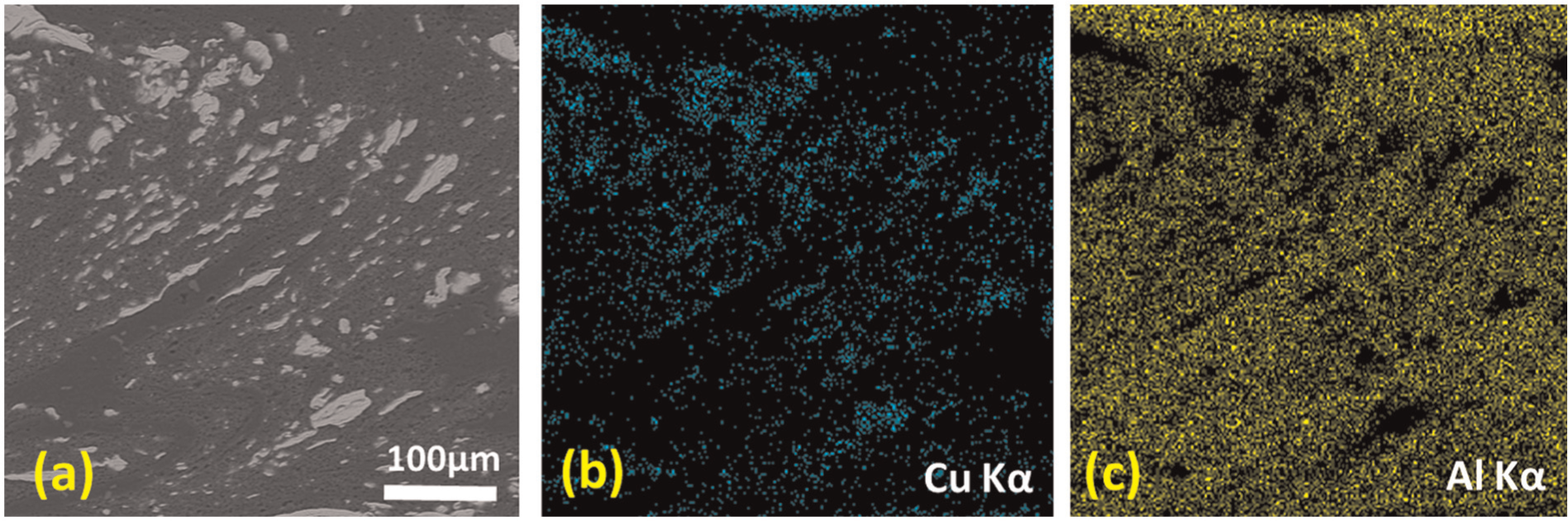
The element distribution analysis maps for specimen conducted at 1250 r/min: (a) an area in stir zone; (b) distribution of copper; (c) distribution of aluminium.
Figure 7(a) shows the SEM macroscopic appearance of an Al–Cu joint. A dark and gray region with a different structure and composition of base materials and full of particles has been formed in the stir zone at the interface. By rotating and moving the pin, some pieces of Cu, as proved by maps, cut off from the copper plate and spread in aluminum matrix and formed a particle-rich zone in the stir zone. Particles are spread irregularly and randomly in aluminum matrix with different sizes and shapes. Some defects were seen at the bottom of the joints of specimens conducted at 600 and 1250 r/min. A closer look at defects and their locations indicates that voids and defects were formed at particle surfaces or on the edge of the dark area.
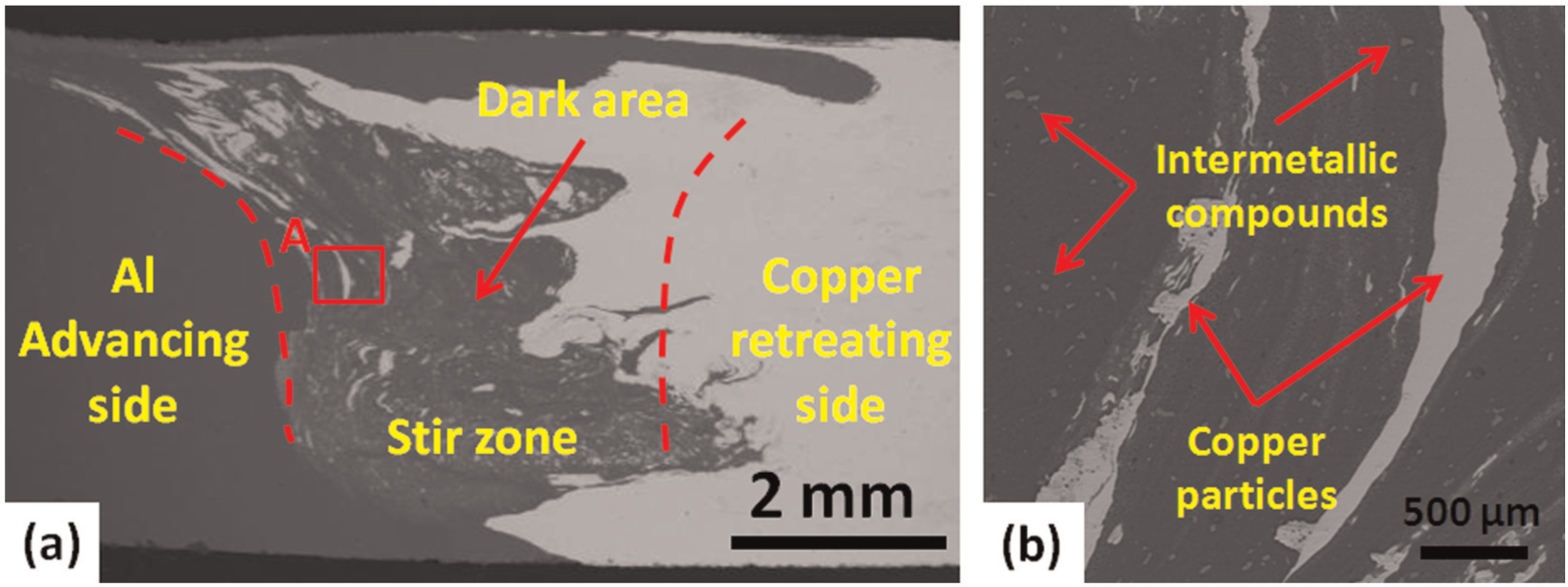
SEM images of the FSW of Al–Cu joint that was conducted at 1250 r/min: (a) cross-sectional macrograph of the joint and (b) magnified view of the region A as marked in (a).
Figure 7(b) shows a magnified view of Cu particles in stir zone that scraped from copper plate. An area with similar morphology and structure to what was seen in the stir zone surrounds these particles. In addition to very small copper fragment that spread in stir zone, there were some fine particles in the matrix which had different contrast from copper particles (Figure 7(b)). Based on the Al–Cu phase diagram, aluminum and copper are incompatible and produce intermetallic components at temperatures higher than 120 °C. Thus, due to rising temperature during the process, intermetallic compounds are formed in the stir zone as well as the interface. Thus, in the dark area, the particles inside the stir zone and the structure formed at the interface can be mainly intermetallic compounds that formed during the process. The XRD analysis was used to specify the structure and composition of dark area and particles inside. XRD results from a cross section of a joint are shown in Figure 8. In addition to Al, Cu and Mg that obviously had visible peaks, Al4Cu9 and Al2Cu clearly was identified. Comparison of what was observed in the SEM images with the morphology of Al4Cu9 and Al2Cu confirms the XRD results. So, stir zone and inside particles as interfaces consisted of Al4Cu9 and Al2Cu that are intermetallic compounds of Al–Cu. Comparison of the extent of the dark area and the amount of particles can be a scale to specify the effects of parameters on change in the formation of intermetallic compounds. Also, the intensity of the peaks in the XRD tests, changes in the size of dark area and the amount of particles are the criterion for evaluating the effect of parameters on the amount of intermetallic compound formation. Comparison of intermetallic compounds intensity peaks with the base metal peaks at each XRD tests results indicated that with increasing rotation speed, intermetallics peaks increase, which indicates increasing amount of intermetallic compounds.
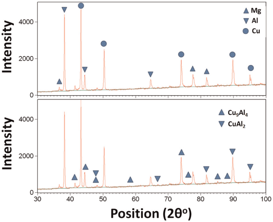
X-ray diffraction (XRD) patterns of cross section of Al–Cu joint that was conducted at 800 r/min.
Intermetallic compounds and copper particles can improve the joint strength by dispersing in the structure and forming a composite, and can weaken the joint by raising the possibility of defect formation, particularly cracks, which formed and started on the surface of the particles. So how the particles affect the strength depends on the size and amount of the particles in the structure. Figure 9 shows the tensile properties of base metals and Al–Cu welded joints. The welded joint conducted at the tool transverse speed of 40 mm/min, rotation speed of 800 r/min had the greatest strength, 215 MPa, about 96% of the weaker material.
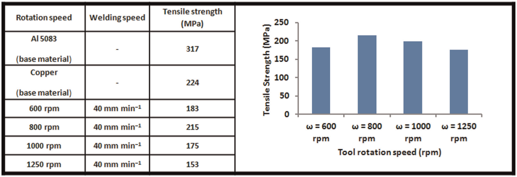
Tensile test results for specimens.
Joint strength initially increased by increasing the rotational speed (up to 800 r/min), and then especially at more than 1000 r/min the strength reduced. Increasing the rotation speed improves the strength by uniform and proper materials mixing. Although increasing the rotation speed improves the strength, formation of larger intermetallic and copper particles have an adverse effect on the strength and weaken the joint. At higher rotational speeds, more intermetallic compounds are formed and due to increasing the possibility of formation of defects and the fragile nature of the intermetallics, strength of the joint is reduced. At low rotation speeds, increasing the mechanical mixing of the materials by increasing the tool rotation speed increases the strength of the joints. Also, the intermetallic compound particles dispersed in aluminum side make a metal matrix composite and improve the joint strength.
Tensile specimens had a little deformation before fracture, and no necking was observed in samples. Also, a sudden failure occurred, which was a sign of brittle fracture. Seeing the cross section of the failed joints indicated that specimens failed at the interface. Magnified view of fracture surfaces is shown in Figure 10. The fracture surfaces contain both cleavage planes and dimples, which indicate that a combination of brittle and ductile failures occurred. Dimples do not have much depth, and their depths are reduced by increasing the tool rotation speed, which reveals specimens have slight deflection before failure. At low rotation speeds, the fracture surface shows a layered structure because of mechanical mixing of materials at low speeds which is not observed at high speeds. By increasing the rotation speed, as shown, the presence of dimples was increased. However, because dimples have a little depth, the joints show brittle behavior in tensile tests. Results of EDS analysis from three zones on the fracture surface confirmed the significant existence of intermetallic compounds on fracture surfaces. These particles had sharp edge and flat surfaces in line with fracture surface. The micro cracks were observed on the particle surface. The cracks began at the edge of particles and expanded, which indicated the brittle failure.
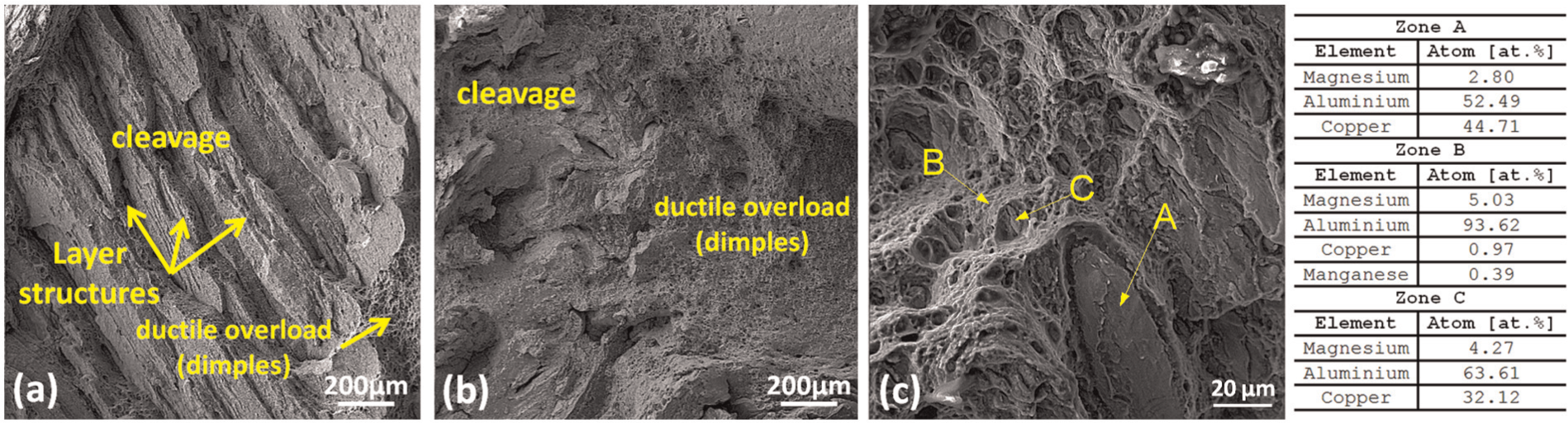
Magnified view of the fracture surface of the joint: (a) in specimen conducted at 600 r/min, (b) in specimen conducted at 800 r/min and (c) EDS analysis results in specimen conducted at 800 r/min.
Conclusion
The dissimilar plates of commercially pure copper and Al5083 in butt condition were connected by using FSW. The sound joint was achieved, and the effects of the tool rotational speed on the mechanical properties and microstructure of the joint were studied.
There were particles in aluminum matrix near the interface, and map analyses specified these particles are copper that scraped from copper plate and spread into the aluminum matrix. An area was formed in stir zone with a composition different from base metals, and some fine particles were spread inside. The XRD and EDS analyses determined that the particles and the area are intermetallic compounds that were formed during the process, and the analyses indicated that intermetallic compounds mainly formed in the stir zone were Al4Cu9 and Al2Cu. The intermetallic particles were distributed with different sizes and shapes in the stir region. The extent of the dark region and distribution of the particles was increased by increasing the tool rotational speed.
The joint that was conducted at the tool traverse speed of 40 mm/min and rotation speed of 800 r/min had the best appearance and strength, which was about 215 MPa, approximately 96% of copper. The tensile test specimens were fractured at the interface with little deformation. The fracture surfaces showed the combination of soft and brittle failure; however, the brittle fracture was the main dominant. Intermetallic compound particles were observed on fracture surfaces.
Footnotes
Declaration of Conflicting Interests
The author(s) declared no potential conflicts of interest with respect to the research, authorship, and/or publication of this article.
Funding
The author(s) received no financial support for the research, authorship, and/or publication of this article.