
Abstract
In this study, a novel precision finishing process for complex internal geometries using smart magneto-rheological polishing fluid is developed. Magneto-rheological abrasive flow finishing process provides better control over rheological properties of abrasive-laden finishing medium that exhibits changes in rheological behavior in the presence of external magnetic field. The finishing fluid used in this study contains SiC and iron particles with a combination of specific volume percentage of glycerin and liquid paraffin as abrasive, magnetizable and base medium parts, respectively. The smart characteristics of magneto-rheological fluid are utilized to precisely control finishing forces to control surface quality. A hydro-mechanical device is used to provide experimental setup in order to investigate the effects of different parameters on surface roughness. This device consists of a hydro-mechanical power unit, abrasive fluid containers, permanent Nd-Fe magnets, workpiece fixtures and a base frame. Experiments were conducted on austenitic stainless steel (AISI304), aluminum (7075 alloy) and copper (unalloyed) with different magnetic field strength, abrasive particle size and finishing time cycles. It is observed that by decreasing magnetic field strength, the surface roughness decreases in all three materials. Besides, with increase in abrasive particle mesh number, surface roughness tends to be higher. However, there is a slight difference observed through different finishing cycle times. The specific applications of this process are finishing fluid guidelines in precise instruments like capillary tubes in drug delivery setups.
Introduction
Finishing internal profiles in complex mechanical parts with a high surface quality is always being a concern and time-consuming task in many advanced industries. In complicated and advanced engineering parts, traditional finishing processes are not cost-effective, compared to the time spent. Besides, almost in all conventional methods, specifications of applied tools have to be concerned. Other groups of problems in traditional methods are disability to cut materials harder than tools and relative tool–workpiece motion. On the other hand, some machining processes like grinding, lapping and honing are introduced that are known as traditional finishing processes. All these processes work on a multiple cutting-edge mechanism and are incapable of finishing complex geometries and internal surface of modern mechanical parts. Traditional methods like lapping and honing are time-consuming, labor involving, less controllable and the biggest disadvantage being that they can be used only for simple geometries. Grinding has been extensively used for finishing of external surfaces, but it causes thermal degradation of surface properties. Moreover, traditional methods are found inappropriate to finish complex geometries. 1 To have precise machining and fine surface quality in complex parts, one should omit tool motion problems. Some new techniques are introduced to solve this problem based upon chemical abrasion or bonding of multiple cutting edges, with assistance of pressure, flow or magnetic field. 2 To achieve a perfect method for finishing of internal surface in complex geometries, one should precisely control machining force and bonding strength made by external magnetic field. Therefore, magnetic abrasive methods have been proposed. These processes provide a situation in which abrasive particles remove material from workpiece surface. 3 In a new process named magneto-rheological abrasive flow finishing (MRAFF), abrasive particles admixed with magnetic particles dispersed in an almost high viscosity liquid and remove material from workpiece surface.
Umehara and Kalpakjian 4 have reported that magnetic fluids containing abrasive particles were originally used for surface finishing by Imenaka in 1981. In advance, a different class of fluid known as magneto-rheological (MR) fluid was initially investigated by American National Institute of Standards and Technology (NIST). 5 MR materials are in a class of smart materials whose rheological properties can be rapidly varied by applying a magnetic field. MR finishing utilizes MR fluid, which consists of magnetic particles, non-magnetic abrasives and some additives in water or other carriers to polish the materials. 6
MR fluids are suspensions of magnetizable particles such as carbonyl iron in non-magnetizable base medium/liquid such as natural oil, mineral oil, synthetic oil, water or glycol. When magnetic field is applied to the MR suspension, the ferromagnetic particles get dipole and thus aggregate to form a chain of dipoles in the direction of the magnetic field. 7 Since energy is required to deform or break the chain columns, this micro-structural transition is responsible for the onset of controllable finite yield stress. 8 This magnetic fluid medium can completely fill the curves and hardly accessible internal surfaces, while assisting abrasive particles to precisely remove material. 9
Magneto-rheological polishing fluid and MRAFF
MR fluids have been invented by Rainbow 5 in late 1940s. They act Newtonian in the absence of any external magnetic/electric field. Such fluids represent rheological properties after exerting an electric or magnetic field. After applying an external field, their behavior change from being Newtonian to Bingham plastic that its yield stress could be obtained via the following equation 10
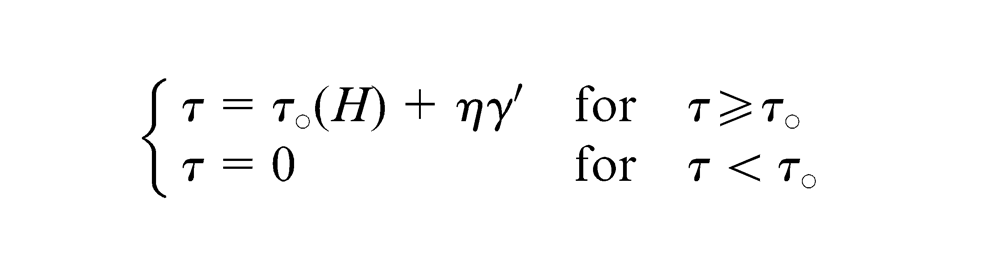
where
The strength of this fluid directly depends on the magnetic field and magnetic particles dispersed in the medium. 11 Using this ability, some scientists have explored a new process for polishing glass into high surface quality. 12 The working mechanism of MRAFF is based on changing Newtonian behavior of fluid into Bingham plastic mode in order to obtain a jelly phase. Then, abrasive particles that are stuck in this magnetic chain will be moved as a result of fluid pressure. Therefore, abrasive particles nearby workpiece surface will impact peaks and break or remove them gradually by scratching. Material removal rate depends on bonding strength, abrasive material hardness, finishing time, workpiece material and abrasive particle size. 2 Some other abrasive materials such as carbon nanotube (CNT), diamond and iron–carbon nanotube (I-CNT) are known nowadays. 13 Recently, a new process called rotational MRAFF (R-MRAFF) is being introduced. In R-MRAFF process, other than the reciprocating motion, the polishing medium is rotated around the axis of the cylinder by imparting a rotational motion to the permanent magnets surrounding the workpiece fixture. 14 Figure 1 shows a schematic mechanism of MRAFF. 2
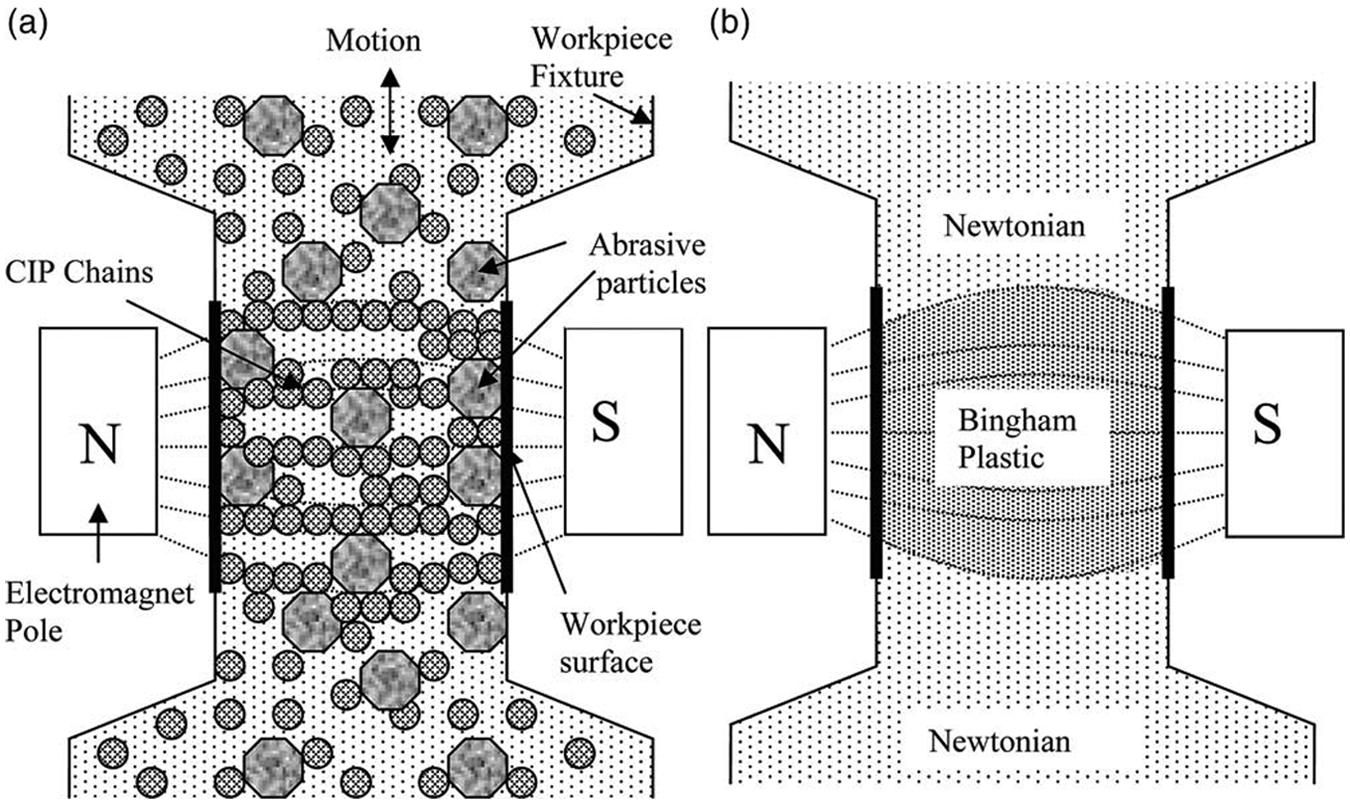
Magneto-rheological abrasive flow finishing process: (a) mechanism of magneto-rheological abrasive flow finishing process and (b) change in rheological behavior of magneto-rheological polishing fluid during finishing. 2
Experimental setup
Experimental device is based on a hydro-mechanical system. A real photograph of the fabricated power units is shown in Figure 2. Magneto-rheological polishing (MRP) fluid is passed through the workpiece due to the high pressure created by the hydraulic system. This system consists of a hydraulic-powered actuator, a mechanical backstroke part, permanent magnets, aluminum fluid containers and main frame.
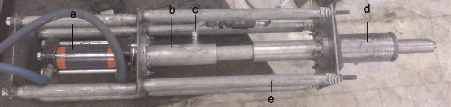
A schematic view of finishing set: (a) hydraulic power unit, (b) lower abrasive fluid container (aluminum), (c) abrasive fluid refill valve, (d) backstroke part and (e) base frame.
Incorporation of the hydraulic part into the mechanical backstroke part maintains pressure in an effective working range of about 37.5 MPa. The system is equipped with polyurethane packing for sealing in the harsh abrasive working condition. This packing system prevents any pressure drop due to leakage in transmission part of the setup. Magnetic field in this system is made by three different neodymium magnet (Nd-Fe) permanent magnets of 0.4, 0.8 and 1.2 T.
Abrasive fluid containers are aluminum cylinders that guide pistons in the desired direction and provide the needed amount of abrasive fluid. In order to prevent any perturbation in exerted magnetic field, these parts should not be magnetizable.
Conducted experiments
Different materials including austenitic stainless steel (AISI304), aluminum (7075 alloy) and copper (unalloyed with 99.9% purity) were used as workpieces. Also, three magnetic field strengths of 0.4, 0.8 and 1.2 T were applied. In addition, finishing time cycles considered in this study were 0.5, 1 and 1.5 h. Approximate initial surface roughness in all parts was 0.6–0.7 μm. The abrasive fluid used in this set of experiments consisted of 20 vol.% iron particles (1200 mesh number), 20 vol.% silicon carbide (SiC; 1200, 800 and 400 mesh numbers) and 60 vol.% base medium (50 wt% glycerin and 50 wt% liquid paraffin). Glycerin helps particle suspension in base medium due to its higher viscosity relative to some other common liquids. Combination of these two liquids leads to a well-lubricated condition and lets particles to be dispersed almost uniquely, while helps achieving a desired suspension of particles. To disperse these particles equally in medium, a high-speed spindle was used for fine stirring.
Results and discussion
Experimental tests were conducted to show the effect of magnetic field strength, abrasive particle size and finishing time on surface roughness (Ra). These tests were conducted on different workpiece materials and in different time periods of finishing process with 3-s strikes of hydraulic equipment. The experimental results have been measured by Mahr Surfanalyzer PS1 surface roughness measurement device. Also, some scanning electron microscope (SEM) images are provided for each piece. SiC abrasive particles of 400, 800 and 1200 mesh numbers have been used. In order to illustrate the effect of each parameter independently, results have been divided into three groups. Obtained results are reported in Figures 3–5.
Comparison between results in different materials.
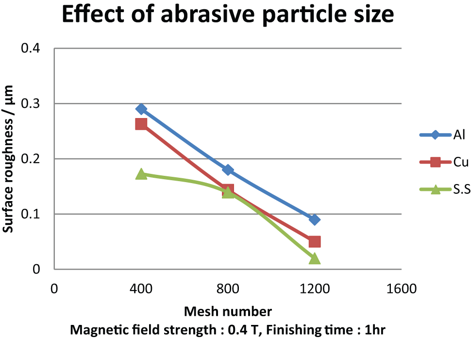
Comparison between results in different abrasive particle size.
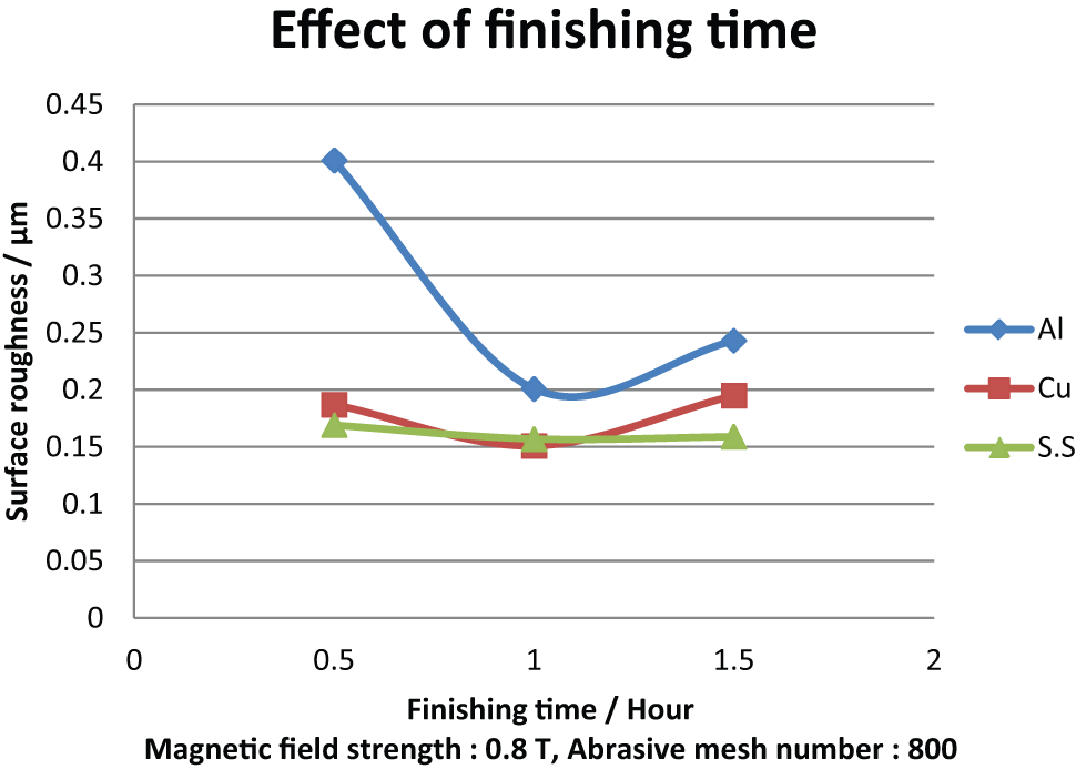
Comparison between results in different finishing time.
Effect of magnetic field strength
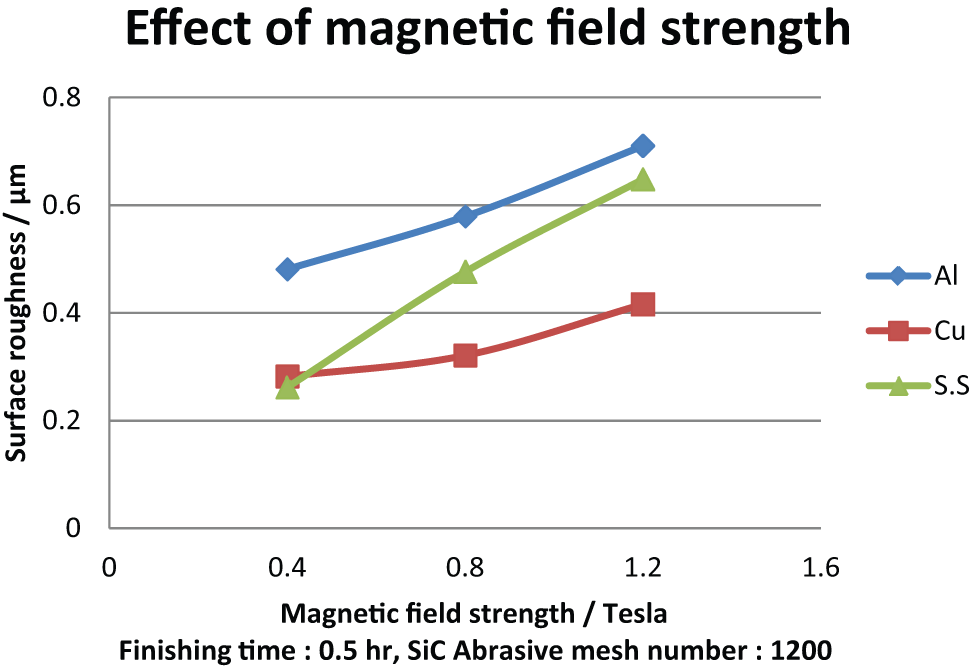
To show the effect of magnetic field strength, other parameters were set as 0.5 h finishing time and SiC abrasive particles of mesh number 400 in different magnetic field strengths. Results of finishing process under these conditions are shown in Figure 3.
From Figure 3, decrease in magnetic field strength results in the reduction in surface roughness of all three materials. Cu has a finer surface quality, and the average surface roughness is lower, compared to the other two materials. The most probable reason for lower surface quality in Al and stainless steel parts could be hindrance made by strong magnetic field and its consequent less motion of abrasive particles close to workpieces’ inner walls. With increase in magnetic field strength, abrasive particles stuck inside magnetic brush and are pushed downward to the surface. So, there will be less material removal along workpieces’ axial path due to less motion of cutting layers (outer layer) of the brush. In high magnetic field strength, abrasive particles are pushed toward workpiece, but they cannot move along axial path due to hydraulic pressure. Therefore, strong magnetic field does not let the particles break the peaks in Al and stainless steel.
In addition, surface roughness results in Cu are better than stainless steel and Al. This happens because of better magnetic properties of Cu and its higher ductility. Higher ductility allows abrasive particles abrade the surface of Cu workpiece easily in different magnetic fields, even with their low motion in higher magnetic field strengths. To ensure validity of this behavior, all other conditions were examined, and almost all results were found to be similar to the achieved surface roughness results.
Furthermore, with decrease in magnetic field strength, surface roughness in stainless steel decreases very quickly. This could be attributed to the fact that AISI304 stainless steel is essentially non-magnetic but becomes slightly magnetic when cold worked. 15 This slight additional magnetic property helps finishing process in low magnetic field strengths. So, in lower magnetic fields, surface roughness decreases to a lower value which results in a better surface quality.
Effect of abrasive particle size
The effects of abrasive particle size are studied, and the results are presented. The experimental conditions have been set to magnetic field strength of 0.4 T and finishing time of 1 h with different sizes of abrasive particles. Results are shown in Figure 4.
Considering results shown in Figure 4, it can be seen that by increase in abrasive particle mesh number, surface quality improves. This could occur due to smaller particles, but in higher number of cutting edges encountered with the surface in higher mesh numbers (smaller particles). Illustrated behavior in the graph was verified through all other conditions with almost the same interpolations. All of the experiments showed results similar to Figure 4. Once again, roughness results of Cu samples were better than those of Al samples but with a slight difference. Abrasive particles abrade surface peaks in Cu pieces easier than Al. This could be referred to difference in material removal mechanism in Cu and Al. It can be assumed that in Cu, because of its more ductile material structure compared to Al, material removal occurs due to crushing. But in Al with more brittle structure, material removal occurs due to scratching. 16 These mechanisms of material removal are very common in ductile and brittle materials. Also, in stainless steel pieces, with abrasive particles of higher mesh numbers, surface quality is better than that of the other two materials. The possible reason could be the harder structure of stainless steel that does not let the bigger cutting edges (bigger abrasive particles) make excessive deep grooves on the surface. However, with increase in mesh number, roughness reduction similarly acts in all three materials.
Effect of finishing time
Finally, the effect of finishing time has been investigated. Results for finishing workpieces in constant magnetic field strength of 0.8 T and abrasive particle mesh of 800 with variable finishing time are shown in Figure 5.
As Figure 5 shows, surface roughness decreases to a minimum point. Then, it increases with different trends between Cu and Al. It means that after a specific point, the finishing process acts inversely and increases the surface roughness. One reason is material removal time. In the first part of the graph, abrasive particles do not have enough time for removing material. But gradually by reaching the minimum point, abrasive particles show their effect and finish the surface to its higher quality. After that, the peaks are removed, and any further abrasion will produce new grooves which decreases surface quality. Concentrating on Figure 5, different behaviors of Al and Cu in the first part of finishing process can be seen. It can be said that in Cu, because of its malleability, finishing process is like padding. Thus, there is no significant change in behavior over different finishing times. But in Al, because of its higher hardness, finishing process will be scratching and removing of high peaks. Therefore, it can be seen that after the minimum surface roughness point, values of Al increase faster than those of Cu.
Once again, in stainless steel, a different behavior has been observed. Regarding all three curves in Figure 5, this result could be drawn that with increase in material hardness, effect of finishing time disappears. Another possible reason for the behavior of stainless steel can be faded cutting edges of abrasive particles after a long period of contacting with a hard surface. This interaction can break abrasive particles into smaller pieces or even can change the geometry of sharp particles into smoother ones. Therefore, due to their incapability of scratching, there is no re-increase in surface roughness after long finishing cycles.
SEM images of finished surfaces
SEM images of finished pieces are shown in Figures 6–10. From these images, surface quality could be completely estimated. From Figures 6 and 7, in a highly abrasive condition, surface roughness will decrease, but its quality drops after a specific point. However, if the finishing conditions get closer to optimized condition, a finer surface shown in Figure 7 would be obtained.
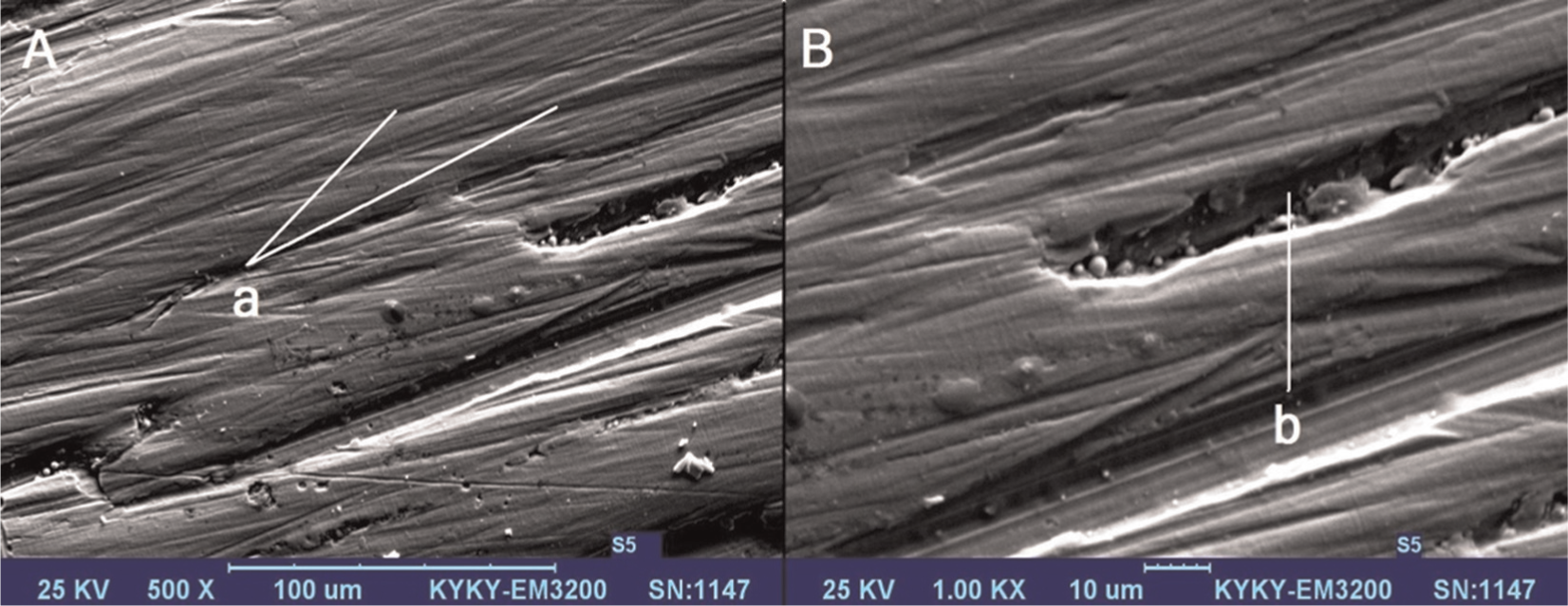
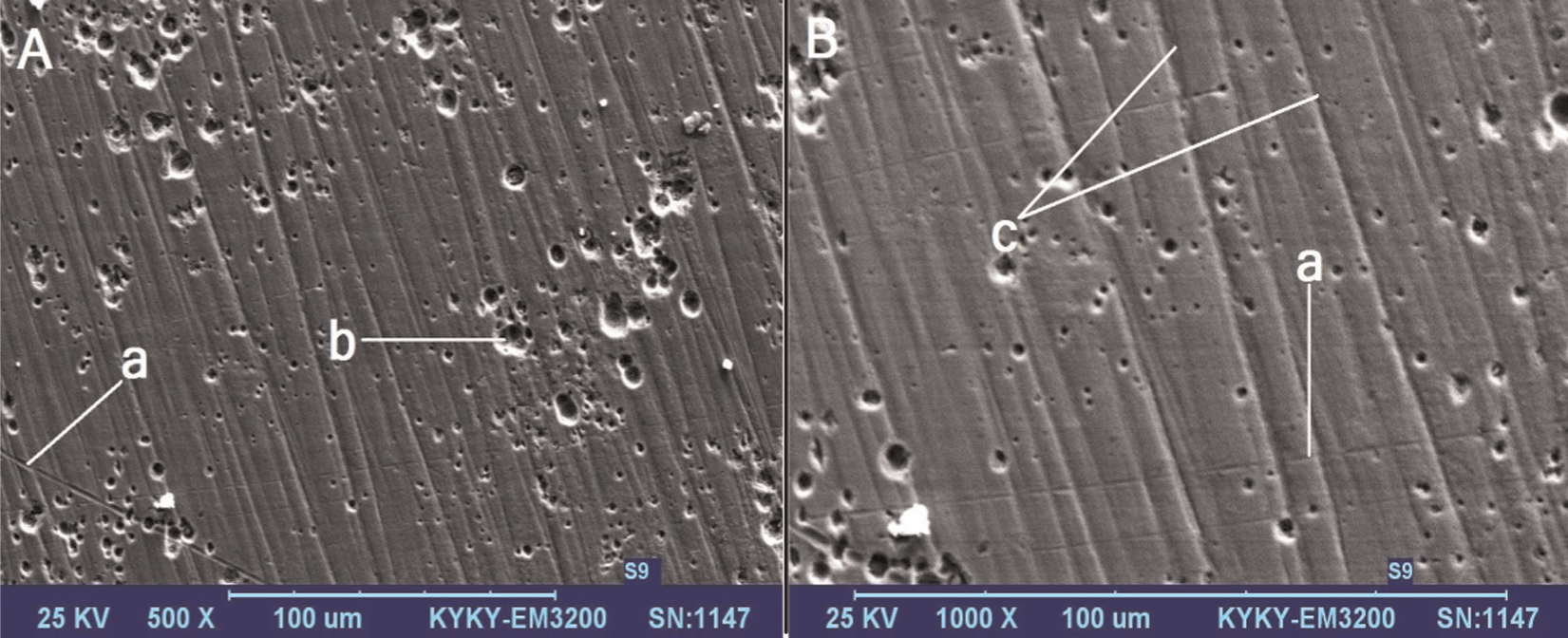
Stainless steel workpiece finished with MRAFF at 1.2 T, 0.5 h and mesh size of 400: (A) SEM micrograph at 500× and (B) SEM micrograph at 1000× (“a” shows abrasive grain marks and “b” shows some porosity in base metal).
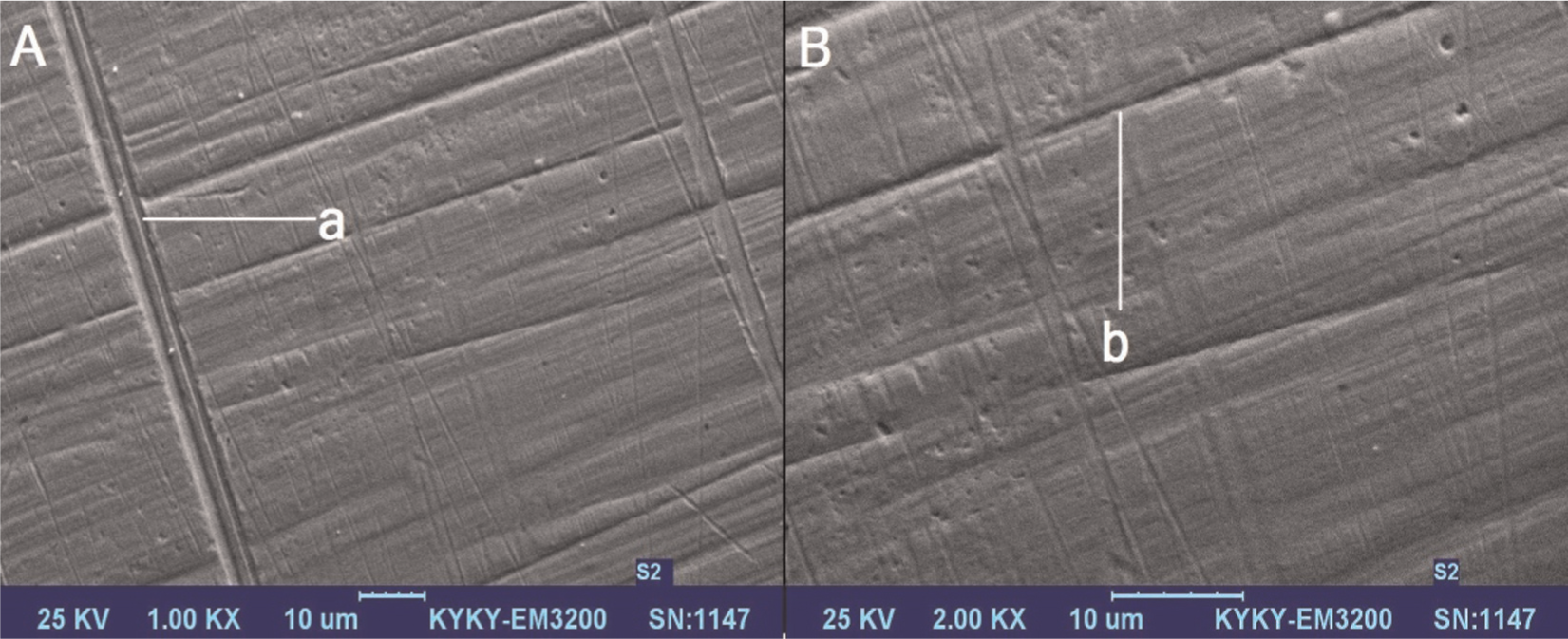
Stainless steel workpiece finished with MRAFF at 0.4 T, 1.5 h and mesh size of 400: (A) SEM micrograph at 1000× and (B) SEM micrograph at 2000× (“a” shows grinding marks and “b” shows deep abrasive grain marks).
Copper workpiece finished with MRAFF at 1.2 T, 0.5 h and mesh size of 400: (A) SEM micrograph at 500× and (B) SEM micrograph at 1000× (“a” shows grinding marks in different directions, “b” shows porosities in base metal and “c” shows deep abrasive grain marks).
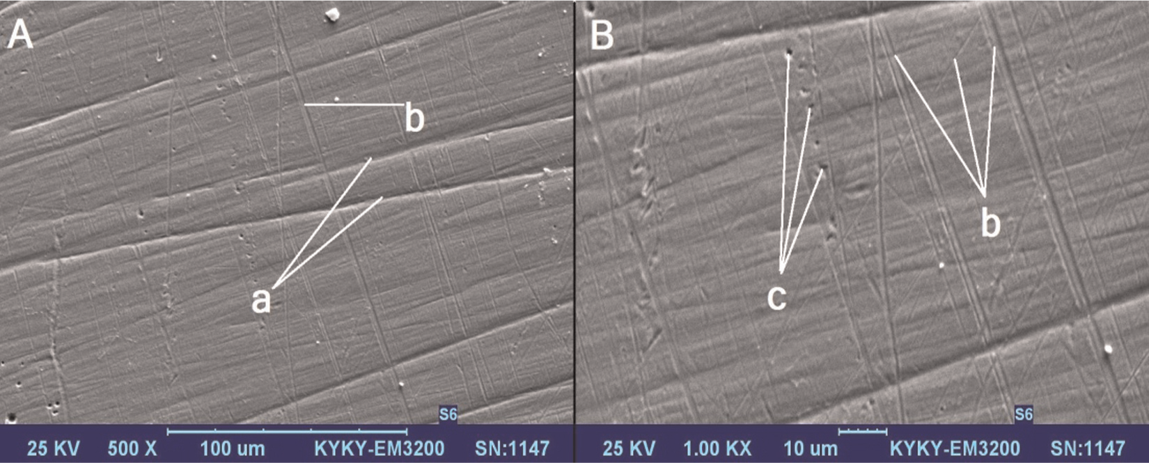
Copper workpiece finished with MRAFF at 0.4 T, 1 h and mesh size of 800: (A) SEM micrograph at 500× and (B) SEM micrograph at 1000× (“a” shows deep abrasive grooves in different directions, “b” shows grinding marks in different directions and “c” shows porosities in base metal).
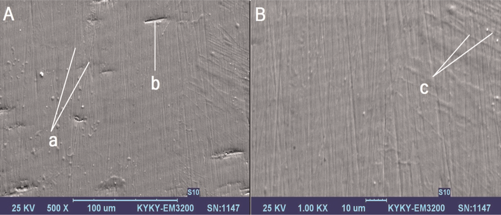
Aluminum workpiece finished with MRAFF at 0.4 T, 1 h and mesh size of 1200: (A) SEM micrograph at 500× and (B) SEM micrograph at 1000× (“a” shows abrasive marks, “b” shows porosities in base metal and “c” shows grinding marks).
If finishing process could not overcome initial surface roughness provided by grinding or porosity, due to weak abrasion conditions, the resulting surface would be as shown in Figure 6. In Figure 6, it is obvious that the surface is almost fine where porosities do not exist. But in the porous areas, finishing medium is incapable of removing porosity perfectly and only abrades its edges. In fact, this could not be a deficiency because MRAFF has to remove high peaks on the surface not its notches.
SEM images for Cu obviously show that surface roughness will change with different finishing conditions. Figure 8 shows one finished surface under a bad finishing condition. “a” in Figure 8 shows grinding lines in different directions. Because initial surface was prepared by grinding, some grinding lines are in irregular directions (“a” in Figure 8). Porosities on finished surface are original and are due to production processes such as casting (“b” in Figure 8). Finishing condition in this sample was not able to remove these porosities thoroughly, so surface remained rough. Concentrating on abrasive marks, effect of abrasive particles with bigger cutting edge is visible (“c” in Figure 8). Poor finishing process in this condition led to such a bad finished surface that not only porosities are not removed but also the excessive depth of some abrasive marks made surface rougher.
Figure 9 shows another finished surface that resulted in one of the best surface qualities. In this image, “a,”“b” and “c” show deep abrasive grooves, grinding lines in different directions and porosities, respectively. Because of better finishing condition and material removal rate, porosities are almost completely removed.
Although abrasive lines have to be completely parallel, in these images, they are not so. This could be due to perturbation of finishing medium through process that may result in some deviations in abrasive lines. This perturbation may occur because of non-uniform magnetic field distribution, unequal initial roughness in different zones or vibrations through finishing process. There are some deeper valleys on prepared surface that may act as a concentration line and speed up abrasion. This leads to deeper grooves even in different directions relative to the original ones. These lines and excessive deep grooves decrease surface roughness. To avoid unreal results made by these grooves, finished surfaces are measured three times for each sample and an average surface roughness value is reported.
Best result in finishing Al workpieces is shown in Figure 10. As it can be seen, deviation in abrasive marks (a) is very little and grinding lines (c) are almost in the same direction. In image A, “b” shows some notches with smooth edge. This proves fine finishing in this finishing condition. However, these notches could not be removed perfectly because this process was mostly designed to remove high peaks on a surface. As a result, these notches lead to a bad surface quality.
Taking into consideration all the above discussion, reasons for the achieved results could be better magnetic properties and more ductility for copper. It has been studied that in ductile materials, material removal mechanism could be in assistance with crushing. This material removal mechanism maintains a uniform behavior and almost in all experiments results in a fine surface. In addition, Al 7075, as an alloy, may have additional materials that do not help to be finished smoothly, while copper samples were made of 99.9% unalloyed copper. Besides, in stainless steel samples, more material hardness and some magnetic properties after cold work (impact of abrasive particles) prevented surfaces to be scratched excessively.
Conclusion
Experiments were conducted under different conditions including magnetic field strength, abrasive particle size and finishing time. The following results are drawn after carefully studying the results:
In all three materials, an increase in magnetic field strength leads to decrease in surface quality. This happens due to excessive normal force on abrasive particles. This force made abrasive particles move toward workpiece surface and penetrate but do not remove any material through reciprocating movement of the medium. This behavior in all of the observations was the same. However, in Cu samples, due to their more ductility properties, more purity and better magnetic properties, surface roughness results are better.
For all three materials, an increase in mesh number of abrasive particles causes a reduction in surface roughness. The reduction trend in all three materials is the same, but surface quality is higher in stainless steel pieces because of their harder structure.
Surface roughness in all conditions decreases up to a certain finishing time (1 h) after which its values increase relative to the minimum point. In fact, after the obtained minimum point, finishing process acts inversely because surface peaks are removed and abrasive particles start to scratch the finished surface. This phenomenon decreases the surface quality after the minimum region.
In all conditions, Cu samples had higher surface qualities than those of Al samples. Besides, almost all surface roughness results in stainless steel samples were better than those of Cu samples. However, with increase in magnetic field strength, Cu shows higher surface quality.
Footnotes
Declaration of conflicting interests
The authors declare that there is no conflict of interest.
Funding
Authors of this article kindly thank the Faculty of Mechanical Engineering of K. N. Toosi University of Technology, Tehran, Iran, for their financial support and scientific advice and are grateful to the Industrial Machine Tool Test and Control Lab, K. N. Toosi University of Technology for providing the equipments.