
Abstract
In this study, a low-cost, flexible process monitoring system for focussed arc tungsten inert gas welder tool electrodes is presented. The system is capable of acquiring and processing geometric data that are used to define acceptance criteria. This system is used to characterise tool wear phenomena in repetitive brazing runs ensuring that the tool is operating within its process window. It was found, using this apparatus, that a build-up of zinc oxide, originating from the zinc-coated steel, on the braze tool prohibits arcing and delivery of a good quality joint. The vision system can identify build-up of this layer before failure of ignition. Measurements showed that after 990 s of continuous arcing, the zinc oxide build-up would cause system malfunction. The vision system gave a warning of zinc build-up at 577 s.
Keywords
Introduction
Automotive panel joining presents a range of technical challenges when designing for manufacture. Due to the strive to reduce weight of the finished product and reducing the number of processes needed to manufacture, welding and brazing technologies are being investigated. Due to corrosion resistance, zinc-coated steels have been used in industry, which present problems when welding long continuous joints. 1 The thin zinc coating applied to the panels has a relatively low temperature of evaporation (907 °C), and the high thermal input required for metal fusion evaporates large volumes of zinc. This leads to poor weld quality which exhibits porosity, and the evolved gaseous zinc forms zinc oxide particulates in the plume of burned hydrocarbons and metal fume, which if inhaled can cause a condition called ‘metal fume fever’ which has been known to be a problem for more than 50 years.2,3 Brazing is a preferred joining method for galvanised materials as the lower process temperatures, and hence, the parent material not melting, dramatically reduce the rate of zinc evaporation and heat-affected zones in the parent material.
In industry, two commonly used techniques are laser brazing and tungsten inert gas (TIG) brazing. This study considers the novel process of focussed arc TIG brazing. Focussed arc TIG brazing and welding, which is based on TIG welding, is a new technology for body in white (BIW) joining of structural parts. 4 Focussed arc TIG brazing competes with laser brazing and is used in production environments where the more costly laser brazing process is not financially viable. Compared to laser brazing, focussed arc TIG requires less complex safety measures, lowering overall system costs and reduced set-up and configuration time. The complete focussed arc TIG system costs about 30% of a complete laser brazing cell. Due to high production volume required and stringent quality standards, process monitoring is necessary for the control of rework. Like laser brazing, focussed arc TIG brazing is subject to potential defects. These include unacceptable aesthetic joints, cracks and holes. All these defects result in reduced performance in high strength and fatigue environments as well as permeability of water.
The brazing operation is dependent on many process variables. Key parameters include braze speed, filler wire feed rate, operating current and the geometry of the electrode and workpiece. These must be controlled and optimised. Numerous process monitoring methods have been employed in weld and braze quality inspection. On-line seam tracking systems have been explored that employ laser line profiling in determining the shape of the brazed joint. 5 Furthermore, passive vision has been implemented to automate seam tracking for TIG welding applications by real-time proportional–integral–derivative (PID) control. 6 For this, a camera has been trained on the electrode tip of a commercial TIG welding apparatus which tracks the movement of the torch to guide it into the seam. In-line ultrasonic sensor analysis is employed in gas metal arc welding to determine weld depth penetration profiles for joints. 7 On-line acoustic sensor analysis of a TIG joint has shown to give a direct correlation between welding sound characteristics and quality of the brazed joint. 8 These methods monitor the quality of the product, that is, the weld or braze, and as such they are unable to pre-empt the formation of defects. This study investigates the use of a low-cost system that could work in parallel with such methods to monitor the health of the electrode between brazing operations and identify deviation in key parameters, so that timely interventions could be planned and defects in the product avoided.
In recent years, tool condition monitoring (TCM) has become significantly more important because it enables a reduction in idle time, which in turn increases production rates and enables a more efficient repair scheme. 9 This technology is currently used in industry for cutting tools, but the same approach can be modified to suit other manufacturing processes. In modern machining tools, 20% of the downtime results from the failure of tools which results in an economic loss and reduced productivity. 10 In a similar fashion, brazing operations based on TIG welding/brazing in the car body manufacture experience a maintenance time of about 10% due to precautionary part replacement of the electrode in the torch head. There is also an increase in need of manual rework of produced parts if the electrode as part of the brazing torch head is not in its optimal geometry, which consumes unnecessary time, space and money.
The trends of TCM are based on an extensive body of research over the last 30 years9,11,12 that has started with intelligent sensor evaluation and is now moving towards vision analysis. 13 Vision analysis has come to prominence with significant gains in resolution and cost of machine vision camera systems. As Kurada and Bradley 10 reported, in the late 1990s, high-resolution charge-coupled devices (CCDs) were very costly or exhibited unfavourable frame rates. With improved resolution CCD cameras, higher quality images are easier and cheaper to obtain. With the aid of low-cost cameras, this study focusses on monitoring electrode condition in an industrial environment. There is a measurable electrode wear in TIG welding and brazing. 14 For ideal direct current (DC) TIG welding, a specific electrode shape is recommended by manufacturers. There are standard sizes that are recommended for usage in the focussed arc TIG system which differ from standard TIG welding electrodes in that the electrode should have a flat tip. 15 While in use, the electrode will change shape due to the specific wear mechanisms and contaminants in the plume created while brazing. This has recently been investigated by Tanaka et al., 16 where they determined that a low boiling point alloying element or coating will evaporate in large quantities and enter the weld plume. In order to determine the ‘health’ of the electrode, this vision investigation focusses on monitoring material loss of the electrode tip and the detection of contaminating material. This wear and contamination occur by means of material loss due to the high temperature resulting from the created plasma and material transfer from the plume. 17
Design of the vision system
A machine vision system has been developed that can observe and measure parameters of electrode geometry, alignment and cleanliness. The vision system is designed to operate as an add-on system to a robotic brazing cell. The system is designed to be extensible to allow for future upgrades, ease of installation and rapid deployment. Figure 1 shows the system-level architecture. The tool measurement image is captured using a low-cost digital microscope that is controlled by the host computer. The host computer then performs the analysis based on predefined algorithms for tracking electrode geometry and the degree of contamination. The camera has optics for factor 20 magnification and a 0.3-megapixel imaging sensor. Commercial computer components are suitable for this kind of system due to the vision analysis being conducted in between brazing cycles.
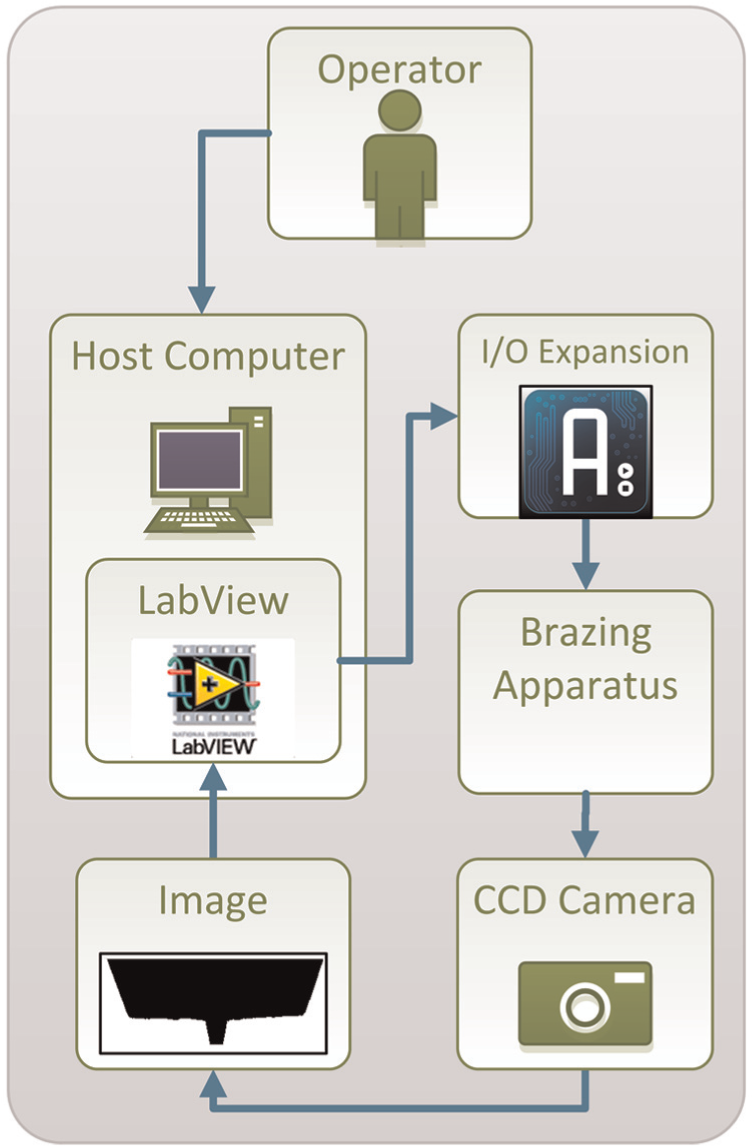
Schematic of nodes in the vision analysis framework.
The vision analysis software used for this framework is based on National Instruments LabVIEW. The hardware is controlled by a combination of a Java-based programming environment that has been programmed to communicate with LabVIEW and Vision Builder, a toolbox for LabVIEW. A LabVIEW front end has been created for operator feedback. This provides control images, calculated process data and the status of the brazing apparatus. An Arduino microcontroller was used to provide input/output (I/O) connectivity and an interface between the host computer and the industrial hardware. This open-source hardware was chosen due to the ease of integration and high level of documentation. It is a low-cost prototyping platform for developing human to device interfaces. Devices that utilise common communication protocols, such as USB, Serial and other protocols, expand the functionality of the host brazing system. This is attractive for other control needs around the focussed arc TIG system.
Good interaction between the user and any TCM system is important, and in the system developed in this work, the hardware and software user interfaces are configurable to the specific needs of the application and the needs of the operator. The user interface, as shown in Figure 2, is designed for ease of use with the key information clearly displayed. All captured images and calculated values are saved to an SQL database for the purposes of traceability in the production environment.
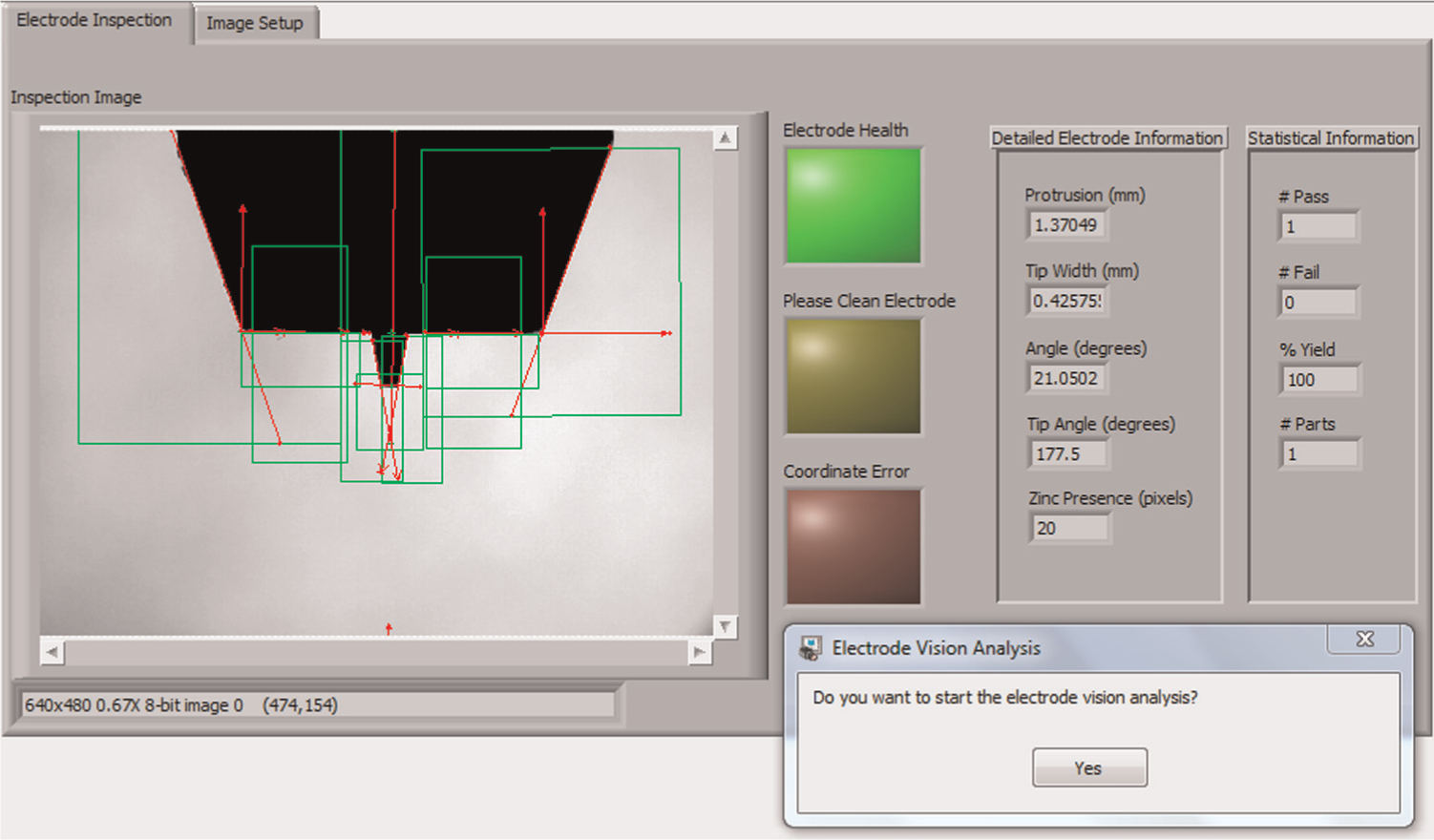
Vision framework UI for the electrode investigation system.
Hardware buttons, on-screen information and feedback status lights are available to the operator to monitor the electrode investigation operational status. Even though the front end of the vision system is developed for operator input and monitoring, this system is designed to work autonomously with the integration of machine sensors such as positional end switches and communication with the brazing apparatus.
Key parameters in electrode monitoring
The brazing apparatus has been employed to deposit a plasma onto flat zinc-coated panels. The following parameters were utilised: a torch speed of 0.1 m/min and 21 A of continuous DC plasma. The employed zinc-coated panel has been manufactured by a galvannealing process. Details of the production standard and layer composition are given in Table 1.
Material information of substrate zinc-coated steel utilised. 18
For all wearing purposes, lanthanated electrodes of the type WL20 were employed. These have excellent arc starting characteristics and have been proven in industry. 19 The wear state of the electrode is assessed by the vision framework hardware and software. The electrode is measured automatically, and the image data are translated to real measurements through a calibration mask. Figure 3 shows the set-up of the camera in situ on the focussed arc TIG apparatus to show how the data are obtained. The substrate steel can be seen on the bottom of the bed. This is where the electrode is focussed in a deployed state.
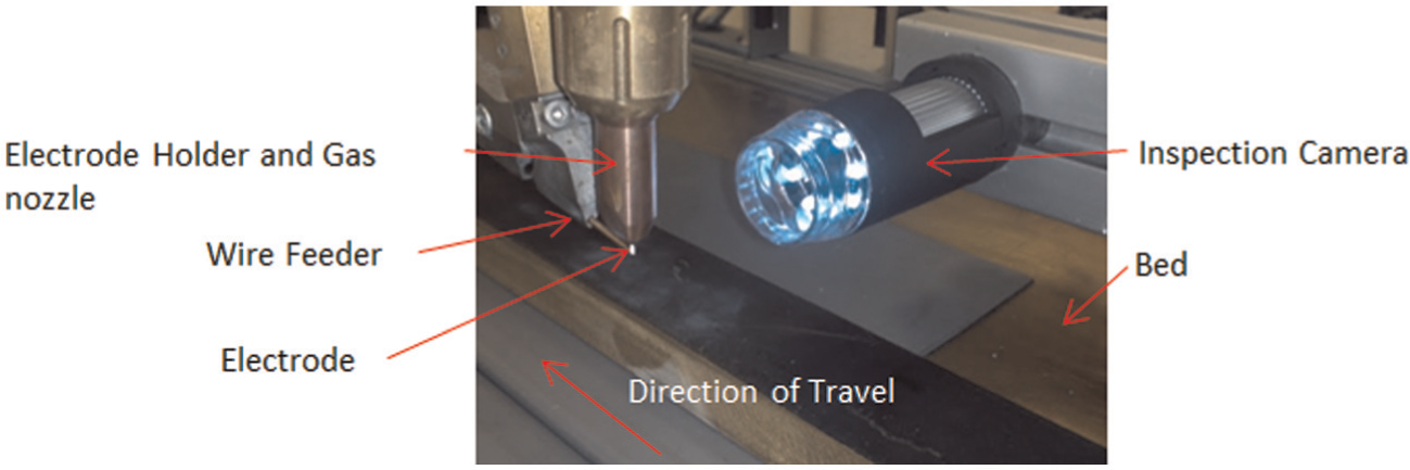
The camera in situ on the focussed arc TIG apparatus.
The working envelope of the electrode is based on four parameters that are deemed critical in assessing the wear and operational functionality. These four parameters are as follows: protrusion of the electrode out of the casing, the electrode angle, the tip width and the tip angle. Examples of electrodes are shown in schematics in Figure 4, where schematics (a) and (b) show the ideal condition, the measurable parameters and a real image inside the casing for comparison. Schematics (c) and (d) show examples of incorrect ground angle and misalignment of the centre axis, respectively. These parameters need to be closely monitored by the vision system in order to coincide with the manufacturer’s guideline that was developed from the machine design. 20 Each parameter needs to stay within a given tolerance to be classed as a ‘Pass’ in the vision analysis.
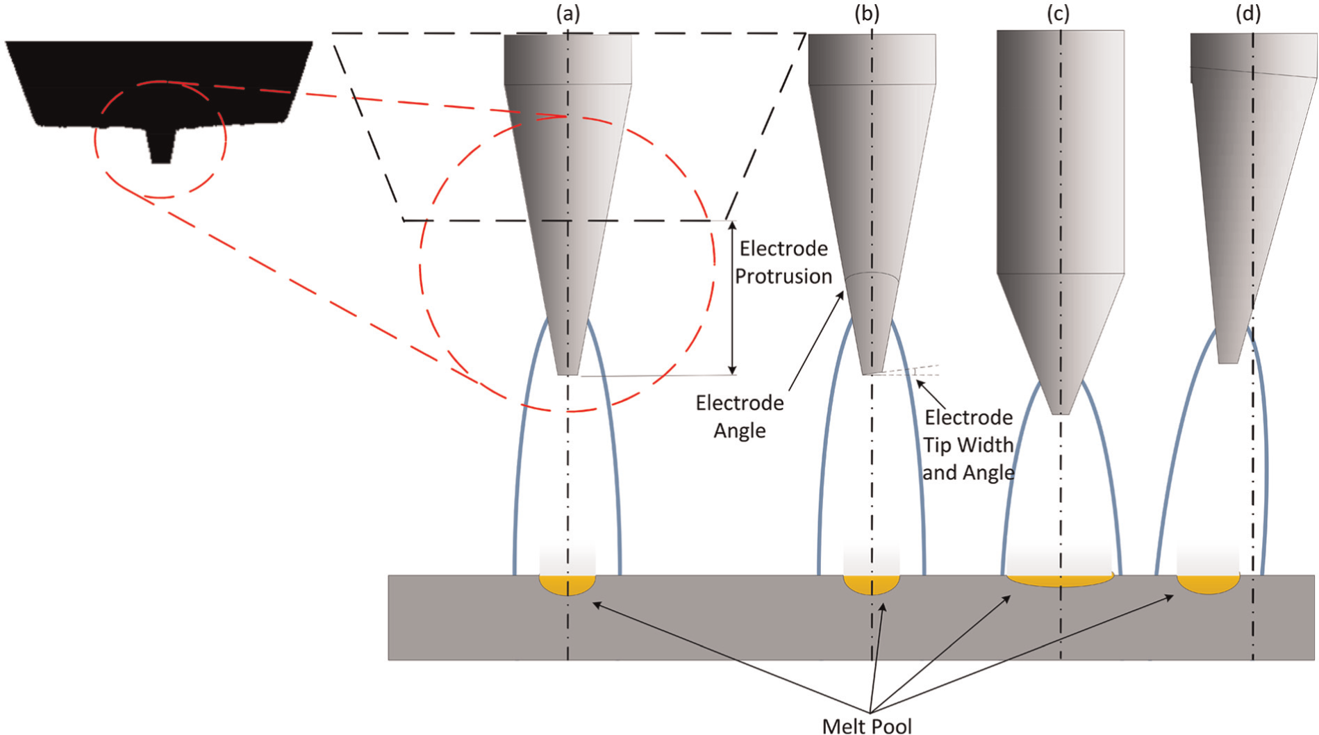
Schematic of focussed arc TIG electrode shape differences with (a) the ideal condition, (b) showing the measurable parameters, (c) a wrong grinding angle that results in a mis-shaped melt pool and (d) issues with misalignment.
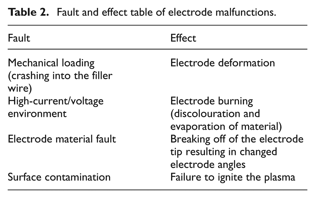
The electrode protrusion is considered the most important parameter based on operator experience and is measured to ensure that the electrode holder is positioned properly and that the spark gap is within tolerance. The manufacturer recommends a gap of 0.7 ± 0.1 mm from electrode to filler wire. The electrode ground angle in conjunction with the gap dictates the plasma profile, spot size and temperature 21 and will affect braze quality. Table 2 describes the effect of some common faults that can be detected by this system. All these faults will impact the quality of the braze.
Fault and effect table of electrode malfunctions.
Establishing the working envelope
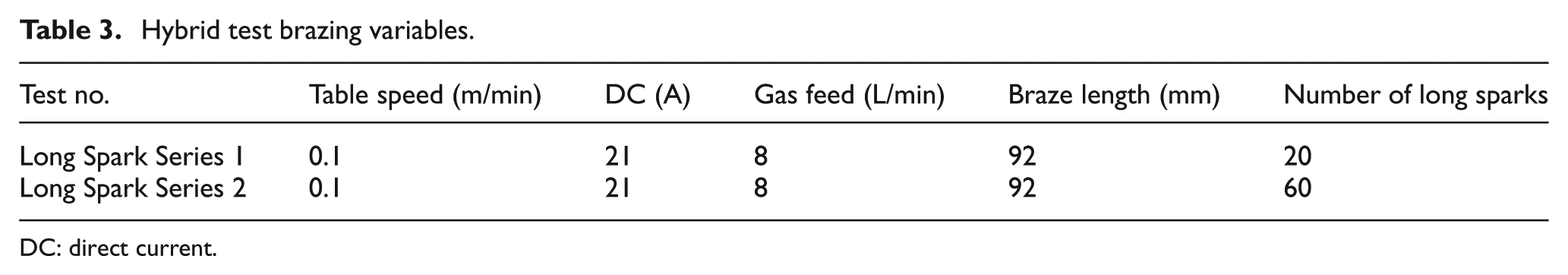
The experimental procedure is designed to determine the effect of brazing time on the electrode geometry and contamination levels, and their subsequent effect on braze quality. For an approximation to full-length brazing, continuous sparking tests were conducted where the focussed arc TIG electrode is creating a plasma on the substrate without a filler wire. A low-power, low-speed approach was chosen to maximise the creation of a weld plume to simulate a worst-case scenario of a brazing environment of joining zinc-coated steels. Depending on the joint configuration, significantly higher braze speeds and wire feed speeds can be used with an increased braze current. For the purposes of this study, however, perfect braze quality was not optimised for but rather an optimised electrode set-up with the geometry being closely controlled and investigated.
Each continuous ‘on-time’ was timed and controlled to ensure constant ‘plasma-on’ times. This wear approach was developed to investigate both a geometrical change in the electrode and an analysis of when the foreign material from the plume impacts the working order of the machine. The parameters, as shown in Table 3, were chosen to simulate a long braze as it would be the case in automotive manufacture. Time was chosen to be kept constant for all long spark tests as the service life of an electrode needs to be quantitatively assessed. Reducing the movement speed of the focussed arc TIG torch, compared to industrial speeds of 1.2 m/min, creates an accelerated electrode wear environment, where the plume develops around the torch head.
Hybrid test brazing variables.
DC: direct current.
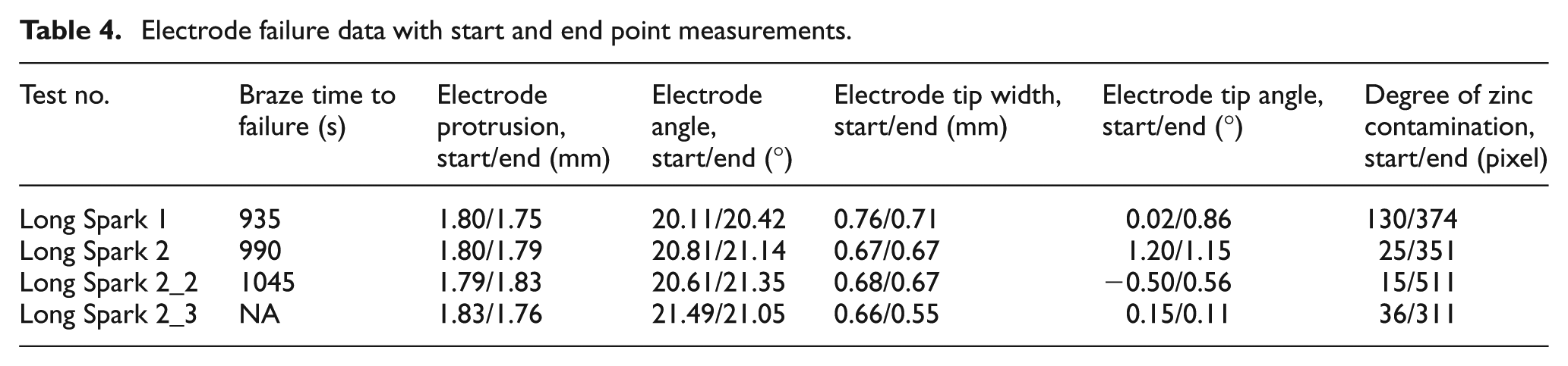
After each long spark, the vision analysis was performed and the parameters of electrode geometry, alignment and contamination were measured. Two sets of experiments were conducted, experiment series 1 and experiment series 2. Table 4 shows these parameters at the beginning and end of the test series. The test series end point is defined as braze time to failure. In these test conditions, there was no measurable change in geometry of the electrode; however, there was a constant change in the degree of zinc contamination. This is shown in Table 4 where the start and end values of each measurable parameter are given. The vision analysis algorithms that were employed found no significant change in electrode geometry over the course of all experiment series but successfully identified the foreign material on the electrode and the casing. As predicted, contamination of zinc vapour from the zinc-coated steel plates was observed to have an impact on the quality of the plasma and the braze.
Electrode failure data with start and end point measurements.
As mentioned above, another factor affecting the quality of the braze is the presence of contamination on the electrode and nozzle. Figure 5(a) shows a clean, uncontaminated electrode and nozzle, and Figure 5(b) shows the build-up of ZnO particulates in the region of the electrode after being in use.
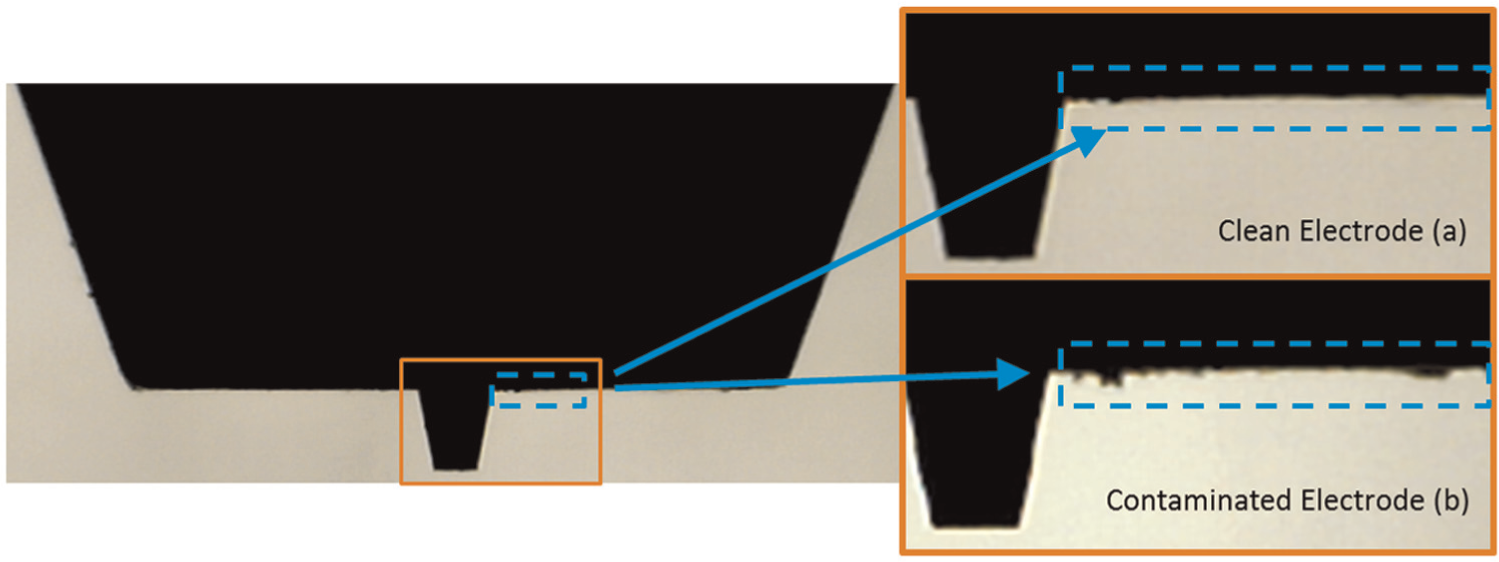
Recorded images from the vision system showing (a) the unused electrode of Long Spark Series 1 and (b) the electrode of Long Spark Series 1 with a foreign material layer at iteration 12. Areas of interest are highlighted.
The powder build-up on the electrode and electrode casing was collected and analysed with scanning electron microscopy and energy-dispersive X-ray (EDX) spectroscopy. Figure 6 shows the zinc oxide powder collected which originated from the galvanised steel substrates, as this is the only source of zinc in the brazing environment. The loosened structure supports the finding in that these particulates have been airborne before settling on the apparatus and in this case on the electrode surface. The presence of carbon in the EDX analysis is due to the fact that the powder was mounted on a carbon tab.
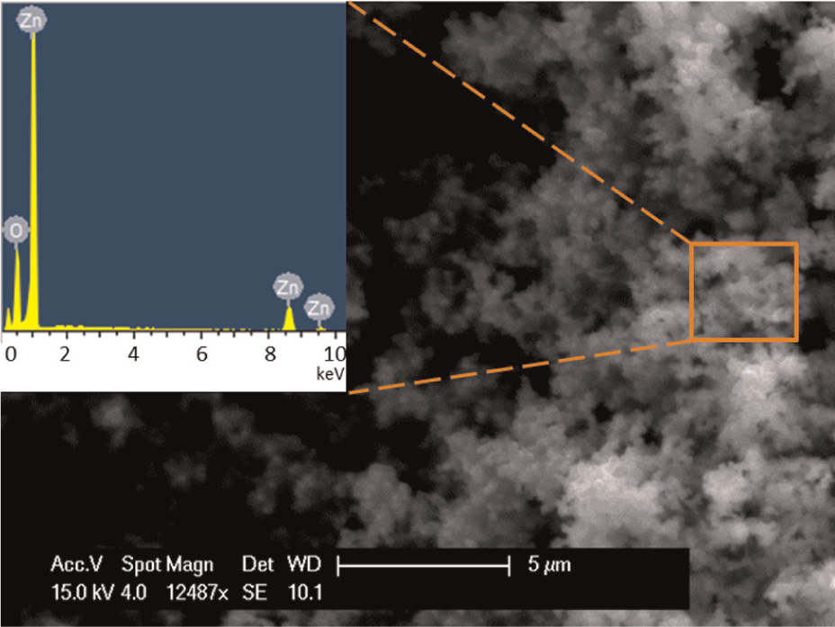
EDX analysis of powdered foreign material adhered to electrode.
The ZnO powder that adheres to the electrode surface raises the voltage required to establish arc. This can lead to uneven plasma profile and temperature, or even a failure to ignite an arc. The presence of ZnO particulates in the areas of the electrode is therefore a key indicator of contamination, leading to tool failure.
The recorded data of the vision analysis focussing on the zinc oxide deposition measurement are shown in Figure 7. The zinc oxide deposition levels were measured by the system as pixels on the shadowgraph image and values were obtained between each long spark. This scale of measurements only hold true for this specific camera and algorithm set-up. Failure points are shown as squares on the experiment series and are defined as the duration of simulated brazing until the electrode failed to spark, prohibiting plasma ignition. Failure points of the electrode failing to spark are indicated with square boxes. After a failure of striking the plasma, the torch head was manually cleaned, removing the visible zinc oxide particles from all surfaces on the torch head.
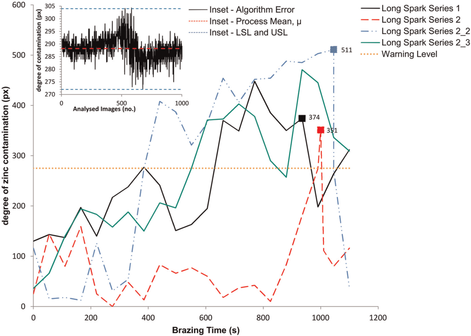
Brazing time versus failure of sparking of electrode. The inset graph shows the variation in the calculated data of 1000 images of the same electrode.
The electrode vision analysis was able to track the degree of zinc contamination around the casing of the torch head. From the data shown in Figure 7, it can be seen that before the failure of the electrode, there is a steep increase in the degree of contamination. Defining a threshold value below the failure values as an early warning level would have permitted preventive efforts to be made in order to keep the torch functioning and hence further create high-quality brazes. This warning level is superimposed on Figure 7 to illustrate at what brazing time such a warning level could flag up. Here, it is defined as 275 pixels.
In experiment series 2_3, there was no failure point to note but there was a constant increase in zinc oxide contamination which reached a peak before declining. In essence, after a certain level of zinc oxide, the brazing process becomes erratic and the working order can no longer be guaranteed.
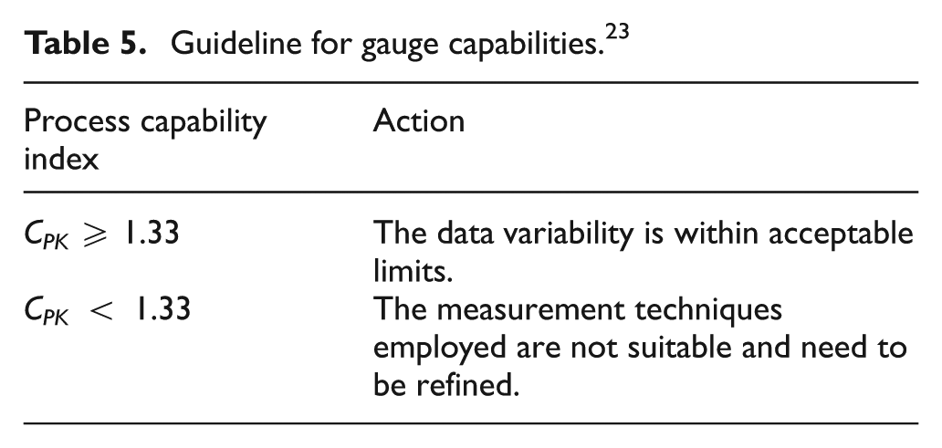
In order to determine whether the collected data on the zinc measurements are accurate and can be trusted, a critical gauge capability index calculation was performed as presented by Pearn and Liao. 22 The error calculation, shown in the inset of Figure 7, contains 1000 images that have been analysed in order to produce a significant data set. Assuming that most, if not all, fluctuations are contained within this set, it can be assumed that the minimum and maximum measurements of the degree of contamination can be used to define the upper specification limit (USL) and the lower specification limit (LSL). The process mean µ is calculated from the full set of data points. These values are then used to determine the process capability index (CPK), which is described by
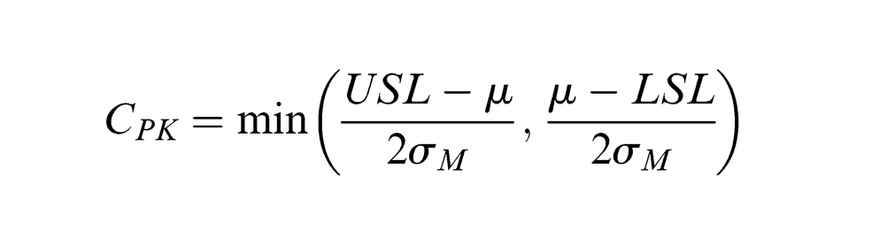
where σM is the standard deviation (SD). A factor of 2 SDs (2 σM) to the USL and 2 SDs to the LSL is employed because of the vision system being utilised in an approximation to an industrial environment where external factors such as changes in lighting, smoke and debris will impact the outcome of the measurement. Calculating the process capability index yields CPK = 1.79. Comparing this value to common guidelines as shown in Table 5 shows us that the data obtained through the vision analysis are reliable enough to measure and analyse the electrode contamination. 23
Guideline for gauge capabilities. 23
The capability index calculation shows that variation in the degree of zinc contamination originates from the brazing process itself rather than the measurement system. This is supported by the fact that the plasma environment at the nozzle of the focussed arc TIG welder is very energetic. The high-pressure plasma will create unpredictable levels of contamination.
Conclusion
A machine vision system was developed for TCM for focussed arc TIG brazing, specifically focussing on the torch head and the electrode. The following conclusions have been made:
In this study, for the first time, it has been shown that a vision analysis approach can be successfully used in classifying electrode tools for focussed arc TIG machines and that zinc oxide contamination plays a major role in electrode service life of this process when used for thermally joining zinc-coated steels.
Long sparking tests have shown that there is little change in the electrode’s geometry if the apparatus is brazing within its specified working envelope. However, contamination of the electrode by means of zinc oxide powder impacts the service life greatly. After an average of 990 s of arcing on zinc-coated specimen, the electrode had a build-up of zinc oxide prohibiting further sparking. The monitoring system was able to track the build-up of contamination in the region of the electrode.
Based on these results, it was possible to define a warning level of contaminants, specifically calibrated to this application.
In order to determine the validity of the zinc oxide contamination measurements from the vision system, a process capability index calculation was performed on the obtained data, and it resulted in a CPK value of 1.63, meaning the employed camera system and the vision algorithms are suitable for this application.
Footnotes
Declaration of conflicting interests
The authors declare that there is no conflict of interest.
Funding
This research received no specific grant from any funding agency in the public, commercial or not-for-profit sectors.