
Abstract
When a prototype tool for injection molding has to deal with undercut features, the difficulty involved in manufacturing the tooling increases considerably as slides must be used. However, the use of slides in prototype tooling has not been extensively explored. Various design and manufacturing issues, mainly related to the geometry, accuracy and extraction of slides, may prevent these working satisfactorily in a multi-piece mold. In this work, the main types of undercuts are analyzed and some issues related to the design and manufacture of slides for prototype tooling are discussed. A study is carried out to understand a specific issue related to peripheral milling accuracy, and a fit procedure is proposed to overcome this. Polymeric inserts for a test part were manufactured following the proposed design and manufacturing recommendations and fit procedure. The mold was used to produce polypropylene prototypes in an industrial injection molding machine. The results showed that similar design and manufacturing concepts can be applied to different types of undercuts. Extraction of the slide worked satisfactorily, and ejector pins were not required. Finally, the proposed solution to ensure computer numerical control machining produced an adequate slide fit proved successful and significantly reduced post-processing time.
Introduction
Prototype tooling involves the use of a die or mold to test a new component design, a new material or a new process. 1 It may also be used to produce functional prototypes or for low-volume production runs. 2 According to Altan et al., 1 while the cost of prototype tooling is not a primary concern, the time needed to produce the tool must be kept to a minimum and is typically only a few days or weeks because of product-development constraints. The core and cavity inserts for this kind of mold can be produced in polymeric or metallic materials either by rapid tooling techniques (using additive manufacturing (AM)) or, more traditionally, by computer numerical control (CNC) machining.2–5 Rapid tooling techniques based on AM have proved to have good potential and a number of advantages over traditional manufacturing processes.2–4,6,7 However, in relation to process accuracy and surface finish, current AM techniques may still require a post-processing stage to finish the inserts so that they satisfy tooling requirements. Because of the staircase effect and the lower accuracy of AM processes, near net-shape inserts are produced.6,7 According to Ilyas et al., 6 as existing metal layered-manufacturing techniques are not sufficiently precise or cannot generate the surface finish generally required for tooling applications, the combined AM/CNC machining approach they proposed is a suitable alternative.
In both cases (using AM or CNC machining), when a plastic prototype has undercut features and is to be produced by injection molding, the difficulty involved in manufacturing the tooling increases considerably. Such features prevent the molding from being extracted from the mold and require the use of slides, or, as they are also known, side-cores.8–10 The use of traditional slide solutions in prototype tooling would not be appropriate because of the complexity involved in and time required for their manufacture.
Some works have dealt with the automatic design of slides,8–13 but little attention has been paid to certain issues related to the design and manufacture of slides for prototype tooling. For example, as moving parts, slides must not only be finished but also have a good fit with adequate clearance to avoid galling and flashes during the injection process.
In a previous work by Volpato and De Amorim, 5 the main (primarily geometric) limitations of CNC milling for prototype tooling were investigated and a procedure for dealing with them was proposed. The results showed that the use of manual post processing to achieve an adequate fit between removable inserts (slides) and their beds was not only time consuming but also inefficient, with some flashes appearing during the injection process. Peripheral milling was used but failed to produce a good fit directly from CNC machining. This can be seen as a limitation of the accuracy achievable with this technology when it is used to produce slides for prototype tooling. Although this earlier study addressed the production of slides, the subject was not investigated in detail.
In this work, the main types of undercuts are analyzed and some issues related to the design and manufacture of slides for prototype tooling are discussed. A number of these issues apply regardless of the manufacturing process used (i.e. AM or CNC machining). To help the user produce the slides, some design and manufacturing recommendations are presented. A study is carried out to gain an understanding of an important issue related to the accuracy of peripheral milling, and a fit procedure is proposed to overcome this. A polymeric mold for a test part was manufactured following the recommendations and used to produce polypropylene (PP) prototypes in an industrial injection molding machine. The results are then presented and discussed.
Slides in prototype tooling and their requirements
Fu et al. 11 classified undercut features into two types: external undercuts (EUs) and internal undercuts (IUs). While EUs prevent the molding from being withdrawn from the cavity, IUs prevent it from being ejected from the core. The authors also stated that in traditional molds, EUs are molded in by the side-cores, which are withdrawn outward from the molded part before ejection, while IUs are molded by form pins or split cores inside the core and cavity, which are withdrawn inward from the molded part. This difference should be taken into consideration at the slide design stage.
Some works can be found in the literature that deal with automatic recognition of undercut features and present design proposals for traditional tooling or for permanent multi-piece molds.8–11 However, for prototype tooling, automatic actuating slides should be avoided, and preference given to manually operated ones.
Chen and Rosen12,13 proposed a method for automating the design of multi-piece molds for use in rapid tooling. They stated that each piece of the prototype mold can be hand-loaded into a mold base mounted on the injection molding machine platens. During the injection process, the molds are clamped into the holding device, and at the end, each piece can be hand-removed from the mold base to release the molding. To validate their method, a case study using stereolithography to produce the injection mold inserts was described. Unfortunately, the authors provide very few details about any post processing of the multi-piece mold, such as surface finish, clearance and adjustment when putting the various pieces together and when assembling them in the mold base.
Also using a multi-piece mold approach, Volpato and De Amorim 5 discuss a slide solution for an IU in a case study about machined prototype tooling. For undercuts, the proposed design solution involved the creation of a removable slide, which should be extracted together with the molding during injection and removed manually from it later. A clearance value of 0.05 mm for the removable slide was suggested, but some flashes appeared during injection. In fact, the authors struggled to achieve this clearance value directly from the CNC process and opted to leave offset material in the milling operation and remove it in a manual post-processing stage. For the specific regions of interest, which were the small insert walls and their respective beds, a flat end mill was used in a peripheral milling operation (side-wall machining). This type of milling is known to be affected by cutter runout error, which is also referred to as tool setting error. Many works have shown that this error can badly affect the surface profile and accuracy of the part.14–16 Arizmendi et al. 16 stated that tool setting error is the sum of two types of errors: cutter parallel axis offset and cutter axis tilt between the tool and spindle axis. According to Kline and DeVor, 14 cutter runout is an aggregation of errors in cutter grind, tool holder and spindle. In traditional CNC machining, this kind of error could be a limitation in terms of the accuracy required for the slide. Studies into the influence of cutter runout error in the machining of polymeric resins are required, as a way of overcoming this limitation would be of great interest to toolmakers.
Design and manufacturing considerations for external and internal slides
The suggestions described here are based on the general multi-piece mold concept proposed by Volpato and De Amorim, 5 which involved breaking challenging features down into new ones (generating removable slides) that can be produced by milling alone and then assembling the new features in the main mold inserts.
In the present work, the considerations regarding the design and manufacture of slides took into account the limitations of CNC machining as the use of this technology is assumed to be essential for removable slides to have a good fit. However, these considerations are not limited to this technology and can also be applied when an AM process is used to produce the inserts.
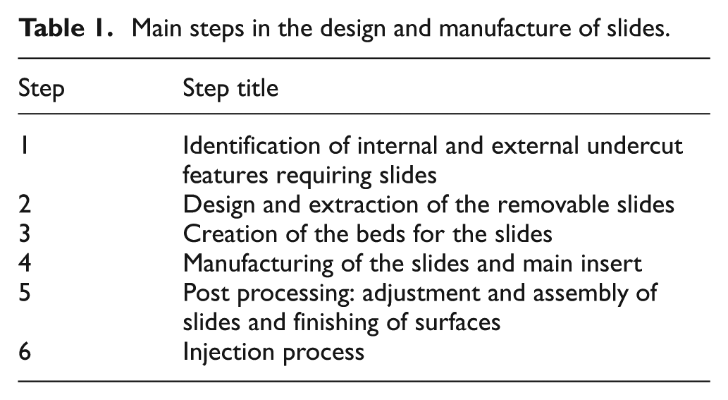
Basically, the idea is to extract the undercut features from the main inserts in a way that the extracted parts (removable slides) and the pocket generated in the extraction command (the corresponding bed) can be milled in either a 3- or 5-axis CNC machining center. The fit between the removable slide and the bed should allow the slide to be extracted together with the molding during the injection process. The main steps in this process are shown in Table 1.
Main steps in the design and manufacture of slides.
Design considerations
Following the definition of Fu et al., 11 a removable slide will be designed for use in the cavity side of the mold when dealing with EU features, and in the core side in the case of IUs. Here, the terms external and internal slides are used to refer to slides for use with EU and IU features, respectively. This basic difference is important when considering the slide extraction mechanism. Two design approaches can be used: (a) the extraction can be performed with the aid of extractor pins, which would push the slide out of its bed or (b) it can be done directly by the molding, which would pull the slide out. As extractor pins are usually in the core side (or moving part) of the mold, their use is optional only for the internal slide. The latter option (approach b) is preferable as it is easy to implement. Additionally, even though the slides are on different sides of the mold, it is suggested that the same design recommendations be used for the geometry of both types of slide. As these two design approaches (extraction by the molding and the use of the same design approach for both types of slide) have not been tested before for external slides, they should first be analyzed experimentally. Table 2 summarizes the main design recommendations.
Main design recommendations for the removable slides.

CAD: computer-aided design; CNC: computer numerical control.
Figure 1 shows a schematic of the removable slide and its bed. It is important to note that the slides and their beds must not create challenging features for the milling process. 5 This is also the case when an AM process that is not accurate enough to produce the main inserts and slides is being used. This constraint should be taken into consideration mainly in relation to the cut geometry to extract the slides in the CAD (Table 2, point 1) because CNC milling may be required to achieve a proper slide fit.
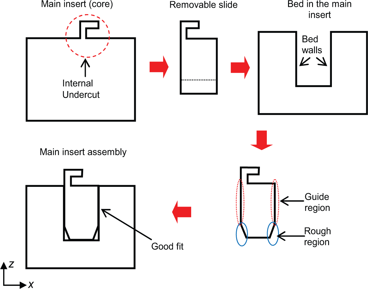
Schematic representation of a removable slide and its bed with the respective main regions of interest.
As shown schematically in Figure 1, in the proposed approach, the lateral surfaces (sides) of the removable slide must have two regions: the guide region and the rough region. Because they are responsible for the fit between the slide and bed, the guide region and bed wall, which are produced by peripheral milling, are the main regions of interest. The rough region of the slide is required during CNC milling but, as it is not important for the fit, is finished manually (roughly and quickly) after machining.
During the design, individual CAD models for each slide should be created. This is necessary because the creation of the bed (step 3) is done by copying the CAD model of the slide into the main insert model in its original status (without the cuts in step 2) and subtracting it in a Boolean operation. To simplify the process, it is recommended that the clearance between the surfaces (the guide region and the bed wall) should be taken into account only during the CNC programming.
Manufacturing considerations
Table 3 summarizes the main manufacturing recommendations for the slides (step 4). The most important recommendation is to machine all removable slides together in one blank. 5 To overcome peripheral milling inaccuracy due to runout, a specific CNC fit procedure is suggested here. First, the CNC code containing the tool paths for the peripheral milling, which is used to finish the bed walls, should be separated from the main CNC program. This CNC finishing code should be created with no offset value, that is, the bed walls should be machined in accordance with the cut command. During the manufacturing process, the removable slides have to be machined first and then the rough regions hand finished (see Figure 1). When the slides are ready, the main insert is machined. Once the CNC machining of the main insert is done and with the insert still clamped (fixed) in the machine, the finishing tool path program should be executed. The slides can then be tested to see whether the fits are satisfactory. If they are not, the finishing tool path program should be executed again, but now reducing the cutter radius parameter in the CNC by 0.01 mm, and the fit test repeated. This process is repeated until the right fit is obtained directly by CNC machining. To help in this procedure, during the machining of the beds in the main insert, a hole can be added in the bottom of the beds immediately underneath the slides to make it easier to remove them during assembly tests by inserting a pin underneath so that the slide can be pushed up if it gets stuck. Finally, as the external slide should preferably be extracted first during the injection process, leaving the molding attached to the core side, the clearance for the external slide should be increased further by running the proposed fit procedure one more time. The efficiency of the fit procedure when used with polymeric resin was tested here, as described in the following section. The remaining considerations (steps 5 and 6 in Table 1) are exactly as described in Volpato and De Amorim 5 and for the sake of conciseness are not included here.
Main manufacturing recommendations for the removable slides.
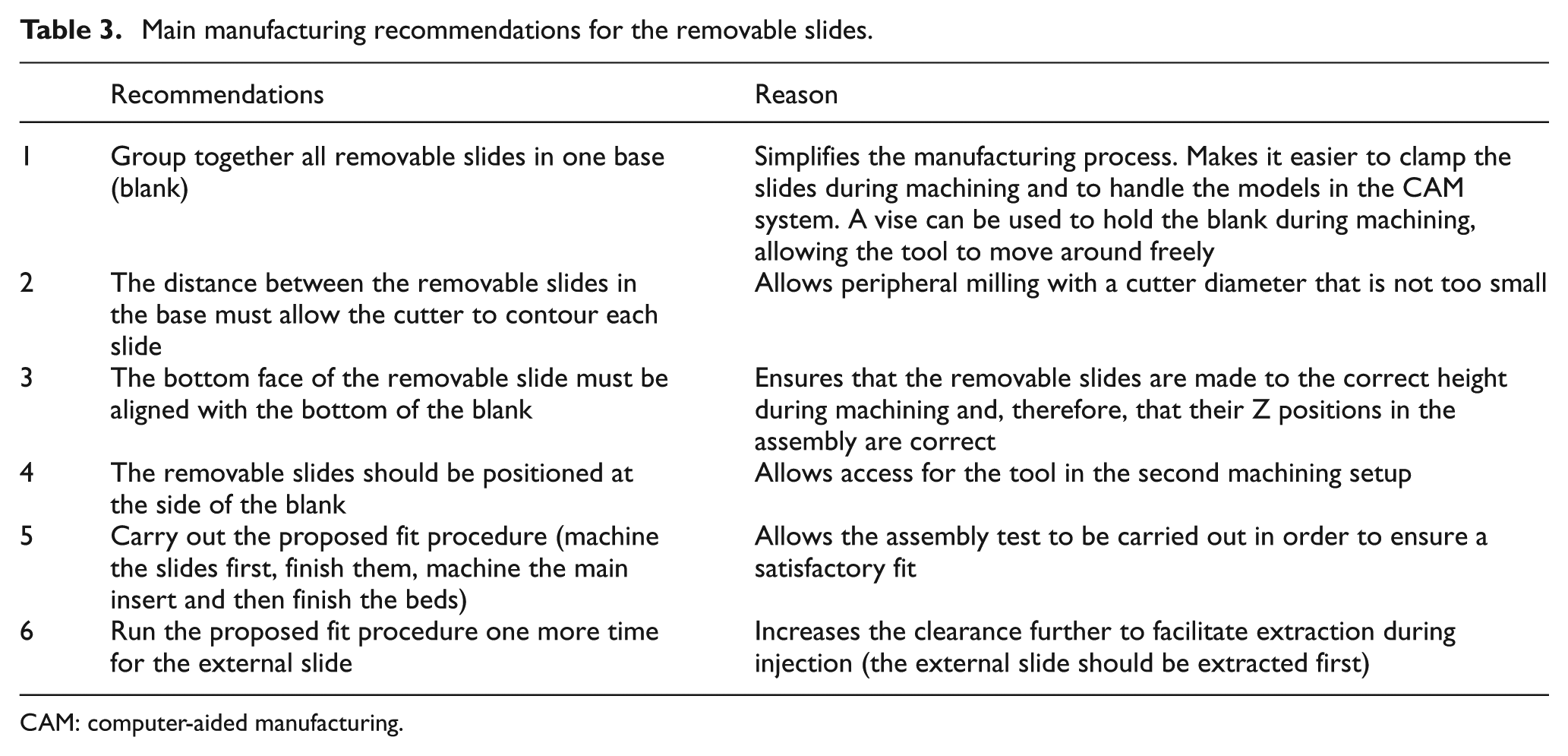
CAM: computer-aided manufacturing.
Experimental studies
Two studies were carried out in this work: a preliminary study to provide a quick analysis of the accuracy of a specific CNC machining system, and another to investigate the issues discussed in the previous section in a real application.
Evaluation of the runout of the machining system
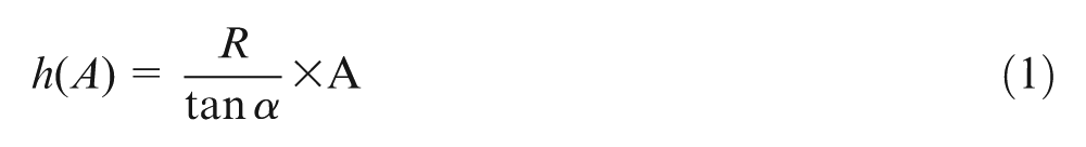
As mentioned before, cutter runout is the sum of spindle, tool holder and cutter errors. Each machining system will therefore have its own particular behavior. Because of this, it is not a simple task to predict or define in advance an appropriate clearance for a specific fit. In order to observe the theoretical influence of tool eccentricity (only cutter offset error at this point) on the machined surface, a model of the cutter assembly was created in a CAD system to simulate this effect (Figure 2(a) and (b)). The classical equations of motion for a circular cam (equations (1)–(3), from Doughty 17 ) were adapted to capture the theoretical profile imparted to the surface of the part as a result of the combined effect of cutter eccentricity, the number of flutes and their helical arrangement.

(a) CAD model and (b) the eccentric circular cam with a translating follower used to analyze cutter runout.
Cutter tilt was not considered in this simplified model. Table 4 shows the variables used in the model.
Variables in the eccentric circular cam model used to study the position of the follower and their values.
In this model, the difference between the follower position at A = 0° and A = 180° corresponds to twice the eccentricity value (cutter offset) and can be measured when a dial indicator is aligned to the center of the spindle (see Figure 3).
Schematic representation of how eccentricity was measured using a dial indicator.
To compare the theoretical surface profile obtained using the model with the machined profile, an oblong-shaped pocket (length: 40 mm, width: 15 mm and depth: 35 mm) was milled in RenShape 5166 polymeric resin from Huntsman in a Cincinnati Milacron Arrow 500 CNC machine (Figure 4). An uncoated two-flute tungsten carbide (WC) 6-mm-diameter end mill assembled with a collet holder was used. Tool overhang was 70 mm, flute length was 50 mm and helix angle was 30°. Rough machining was carried out with successive 5 mm increases in depth of cut, leaving 0.12 mm of theoretical offset material (defined based on previous studies). A single pass (35 mm depth of cut) of peripheral milling was applied as the finishing strategy. Other machining parameters are listed in Table 5.
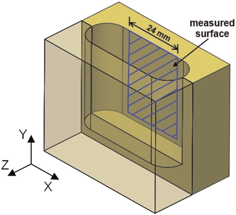
CAD model of the pocket showing the internal surface to be digitalized.
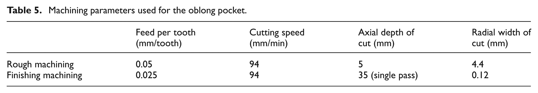
Machining parameters used for the oblong pocket.
The runout offset to be used in the model was measured in the CNC machine using a dial indicator (Mitutoyo) with a resolution of 1 µm in the shank region of 61.5 mm from the tool tip. Additionally, to verify the model experimentally and capture the real profile of each cutter flute, 12 height measurements were taken for each flute. These values were plotted in an Excel® chart and combined to obtain the final profile of interest, which was used in a SolidWorks 2010 CAD system to perform a surface analysis. Table 4 shows additional information about the cutter system and the measured eccentricity.
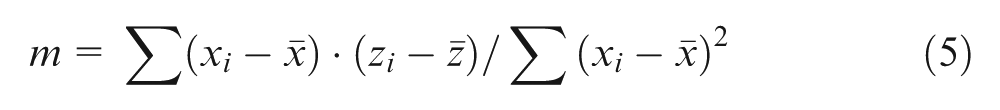
After machining, the pocket was sectioned and the side wall digitalized with a 3D contact scanner from a Roland MDX-40 milling machine (Figure 4). The scanner has a resolution of 0.01 mm, and a mesh size of 24 × 35 mm and step size of 1.0 and 0.6 mm along the X (24 mm) and Y axes (35 mm) were used. MATLAB R2011a software was used to generate the image from the point cloud. To correct any inclination (slope) of the part during scanning, which might be originated either from the machining and/or from the part positioning on the scanner table, an average plane was calculated with the point cloud for each digitalization using Excel®. This was done for the profile analysis to determine the distance from profile peak to valley (see details in the results section). To achieve this, the point cloud was initially translated in the X and Y axes so that the Z axis passed through its center. Then, a linear regression was performed using the X and Z coordinates of all the points (i.e. all the points were projected onto a single plane). The line obtained in the XZ plane is shown in equation (4)

where m is the slope and b is the z-intercept of the xlinear regression line. Both these parameters were obtained using equations (5) and (6)

where xi and zi are the x and z coordinates of the point i, and
A second line, now in the YZ-plane, was obtained in a similar fashion using equation (7)

where n is the slope and b the z-intercept of the ylinear regression line (which is the same value as b for the xlinear regression line).
The two lines xlinear regression and ylinear regression intersect at one point (0, 0, b) and therefore define a plane, as shown in equation (8)

The average of the 10 highest points of the central peak and the 10 lowest points of each valley were computed. The distances from this average peak to the lowest average valleys were used as the result.
Results and discussion related to the evaluation of the runout of the machining system
The theoretical flute profiles from the eccentricity model are shown in Figure 5(a). The values have been scaled up 60 times to make the graphs easier to read. The thicker curve in Figure 5(a) represents the combination of the profiles of the two flutes and corresponds to the deviation that can be expected to be imparted to the surface of the part during machining. Clearly, the model predicts that some peaks and valleys will appear on the surface. The position of the peaks is dependent on the position of the flutes in relation to the center of rotation of the spindle (A0 in Table 4). The measured flute profiles are shown in Figure 5(b), where it can be seen that the upper and lower valleys (of the combined profile) are at different distances from the center of the cutter, that is, the lower valley is further from the tool center than the upper one. This shows that there was some cutter tilt in the assembly, and that this had a significant effect on the profile of the flutes. The average measured cutter tilt was 0.033°. Cutter tilt was not considered in our model.
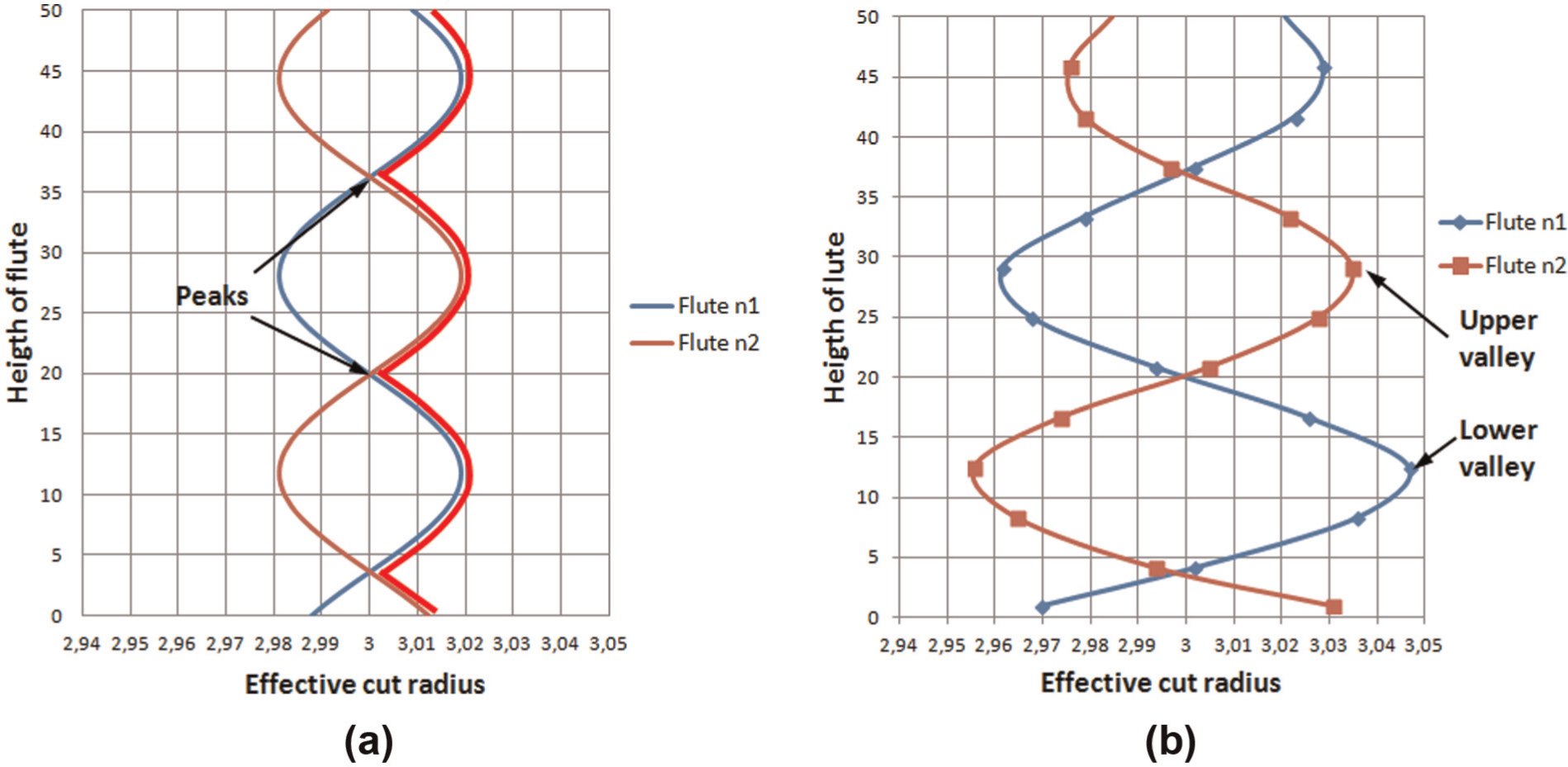
(a) Theoretical profiles of the cutter flutes from the eccentricity model (data from Table 4) and (b) measured profiles.
For a better understanding of the impact of cutter runout on the machined surface, the measured combined profile (Figure 6(a)) was used to create the 3D CAD model shown in Figure 6(b). Figure 6(c) and (d) illustrates the digitalized surface in different views. Table 6 shows the distances between peaks and valleys for the expected surface profile when cutter runout is taken into account (a1 and b1 in Figure 6(a), respectively) and for the digitalized surface (c1 and d1, respectively).
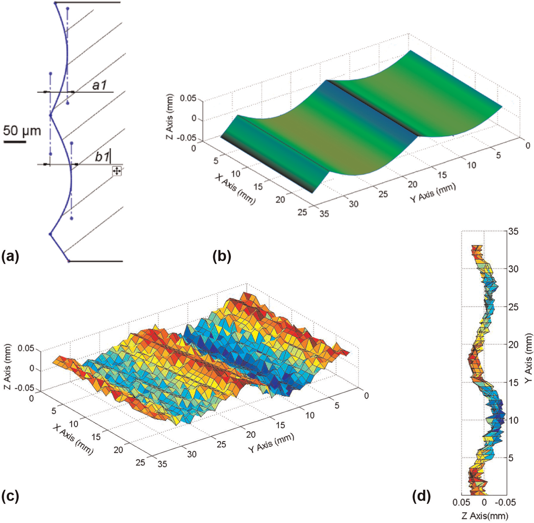
(a) Combined measured flute profile, (b) 3D CAD surface expected from this measured profile and (c, d) digitalized machined surface in different views (all scaled up 60 times).
Values of the deviations shown in Figure 6(a).
Mean values of 10 digitalized points.
The similarity between the expected and machined surfaces is clear, and it can be seen that the combined profile was copied reasonably well to the polymeric resin. Inside a slide bed (pocket), the peaks will generate narrower regions at certain heights, which could affect the fit of the slide fit. The magnitude of the deviation observed here is close to the clearance value mentioned earlier (0.05 mm). Therefore, the runout error combined with the characteristics of the cutter (mainly the number of flutes and their helical arrangement) do in fact influence the surface profile of the machined resin and the final accuracy of the process. This can badly affect the fit of the slide.
As it is not always possible to change cutter runout, some suggestions to minimize the deviation would be to use a cutter with a greater number of flutes and/or a smaller helix angle, as the model shows that this would reduce the height of the peaks. These should be analyzed experimentally though. Another, more time-consuming alternative would be to use more than one machining pass to finish the pocket. By reducing the axial depth of cut, the imparted profile would be less pronounced. However, none of these approaches would allow the clearance required for a good slide fit to be specified exactly in the computer-aided manufacturing (CAM) system. This reinforces the need for the fit procedure proposed and tested here.
Analysis of issues related to the slides
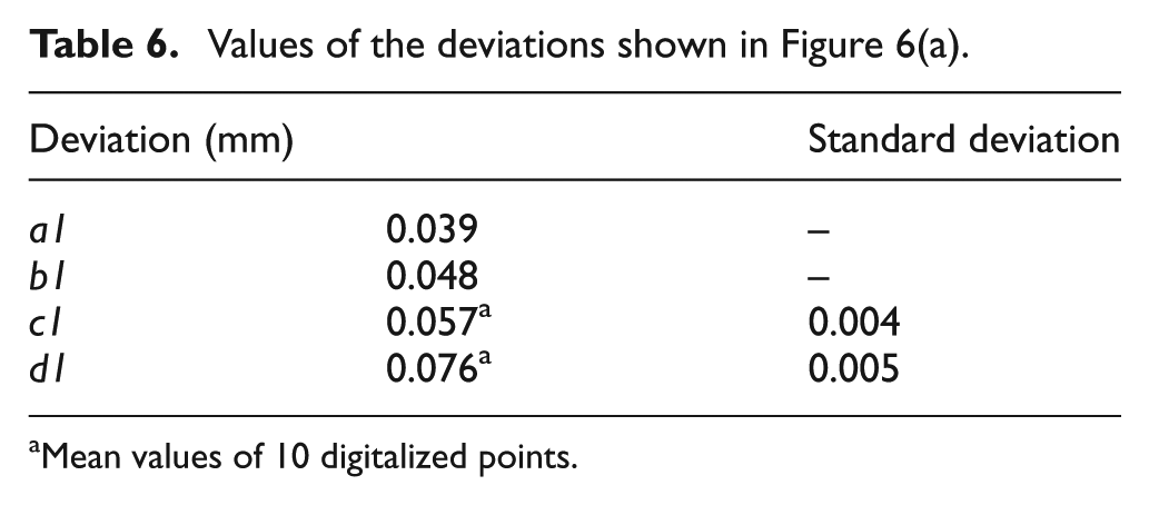
Figure 7(a) shows the geometry of the test part (the base of a mouse case) specially designed for this study. The wall thickness was 2 mm, and the draft angle was 1.5°. A SolidWorks CAD system was used to produce a model of the part and the core and cavity inserts (Figure 7(b) and (c)). The main features of interest are the two clips and the two lateral slots in the case, which require the use of internal and external slides, respectively.
(a) Geometry of the mouse case and (b) main cavity insert and (c) core insert.
Design of the internal and external slides
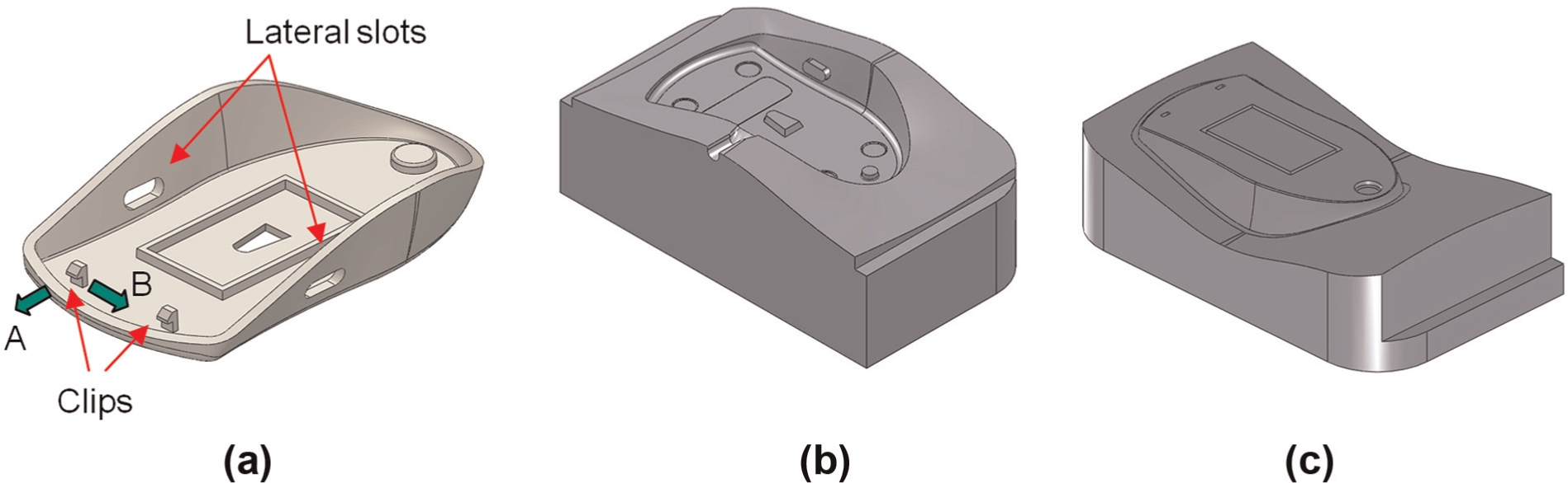
Slides, suitable for prototype tooling, can be designed in a number of ways, the choice of the most appropriate depending greatly on part geometry. When the internal slides in the prototype used here were designed, a particular issue emerged related to the proximity of the clips to one of the walls of the part (see Figure 7(a)). As the clip and the adjacent wall are very close to each other, if the slide was to be removed in direction A, there would be very little room for a slide that did not also include the wall. For this particular test part, and following recommendation 8 in Table 2, direction B could be chosen to remove the internal slide. This can be done by choosing the cut contour so that it passes through the side rather than the back of the clip. In this case, the two slides generated would have to move toward each other when they were extracted. However, there will be cases where this solution might not be possible and an alternative would have to be found. With this in mind, it was decided to take the opportunity to test whether the internal slides could be satisfactorily removed in direction A. This was done by including the wall in the slide geometry (Figure 8(b) and (c)). By doing this, the slide has to be removed by forcing it slightly (rotating it) against the clip to make room for it to be extracted. This must be done immediately after the mold has been extracted, while the polymer is still hot and relatively flexible. The effects of this decision on the molding and on the internal slide were analyzed during the injection process.
(a) Core insert of the test part with the internal slides highlighted and (b, c) the feature in the internal slides that prevents the slide being extracted normally.
As suggested in the “Design considerations” section, extractor pins to push the internal slides during extraction were not included in the design, mainly to reduce the cost of the prototype tool and the time required to use it. However, extractor pins (six) were used to extract the molding.
The external slide idea has not been tested before, so it was decided to test two design options (Figure 9). Option 1, in Figure 9(a), followed the idea of the internal slide exactly, that is, an oblong shape and a single cut in the CAD system, while option 2 minimized the marks on the external surface of the molding but required more than one cut command. Figure 10 shows an exploded view of the assembly containing the main inserts and slides.
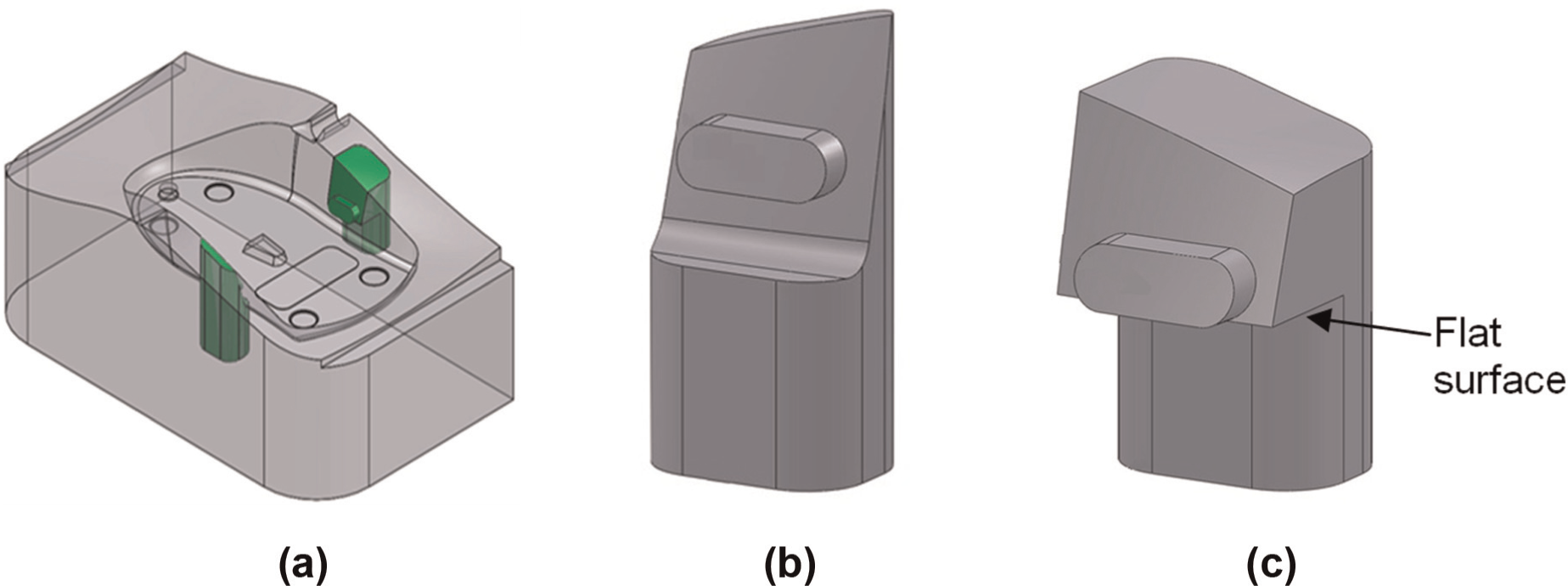
(a) Cavity insert of the test part with the external slides highlighted and the two external slide designs: (b) option 1 and (c) option 2.
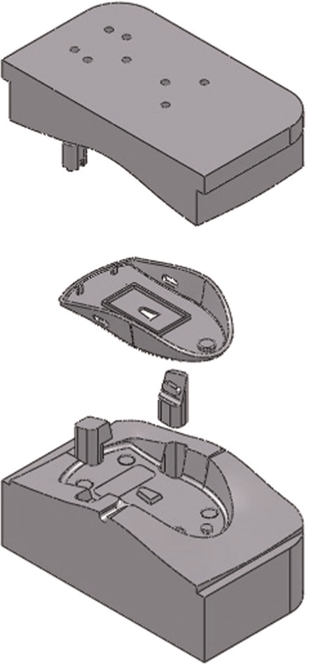
Exploded view of the main inserts.
Manufacture of the main insert and removable slides
The materials used for the inserts and moldings were RenShape 1566 and PP, respectively. PowerMill® 9 CAM software was used to generate the CNC program for a Romi Discovery 4022 CNC machine. This machine was used to see whether the proposed fit procedure for overcoming the runout problem would work satisfactorily on a different CNC machine. Peripheral milling was performed with the same 6 mm two-flute end mill used in the preliminary study (runout evaluation).
Following the fit procedure, the slides were manufactured first, followed by the main inserts. With the main inserts still in the CNC machine, the slides were tested for an adequate fit (i.e. one that allows the slide to be smoothly inserted and removed from the bed, without getting stuck or being too loose). To achieve a good result, the fit test was repeated three times for the internal slides, that is, the finishing program was run with a cutter radius of 3 mm, then 2.99 mm and finally 2.98 mm. For the external slides, one extra run with a cutter radius of 2.97 mm was performed. Final clearance was measured using a digital caliper (Mitutoyo) with a resolution of 0.01 mm.
To expedite the process, the core and cavity surfaces were not hand finished after machining. The time spent designing and manufacturing the inserts and slides was measured.
Injection process—prototype production
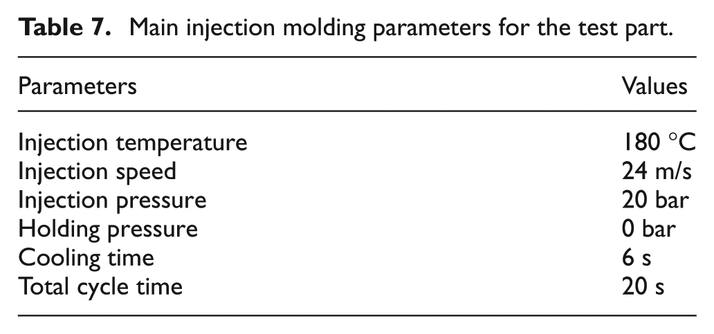
Finally, for the injection process, the main inserts were assembled in a metallic injection mold structure (Figure 11). The injection molding machine used was a Haitian HTF-58X. The injection parameters are shown in Table 7 and were defined after seven shots. Compressed air was used to cool down the insert. After setting up the injection molding system, 33 prototypes were produced.
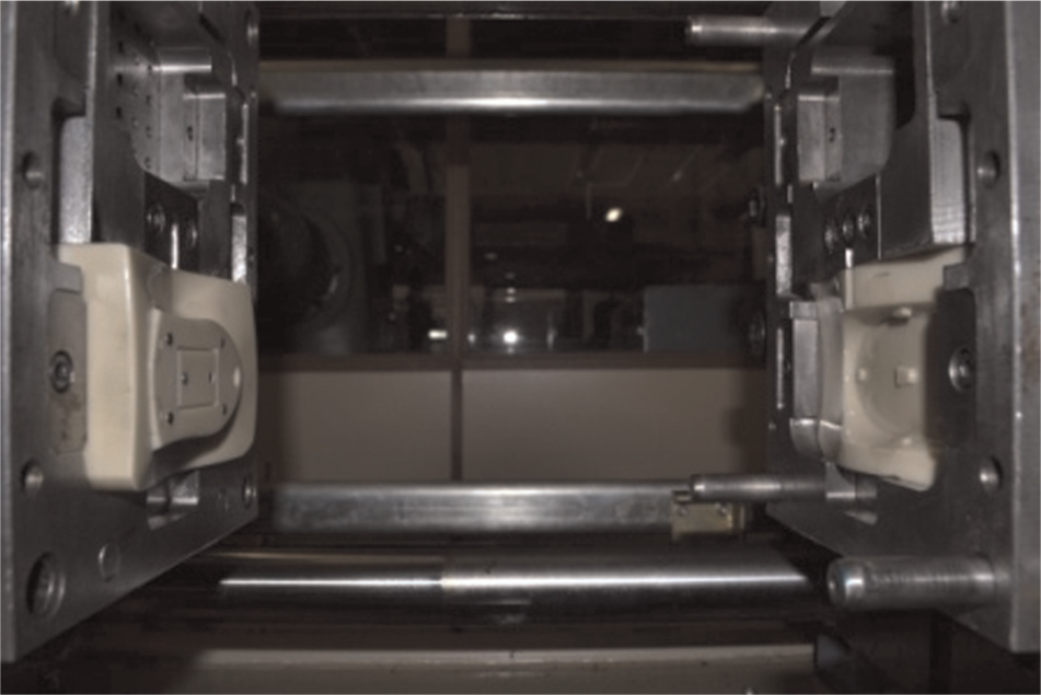
Main inserts assembled in the mold structure.
Main injection molding parameters for the test part.
Results and discussion related to the case study
Figure 12(a) shows that first the external slides were removed from the core cavity by the molding in the mold-opening stage during the injection cycle. After that, the internal slides were extracted from the core insert (also by the molding) in the ejection stage (Figure 12(b)). This was observed for all of the 33 parts produced (Figure 12(c)).
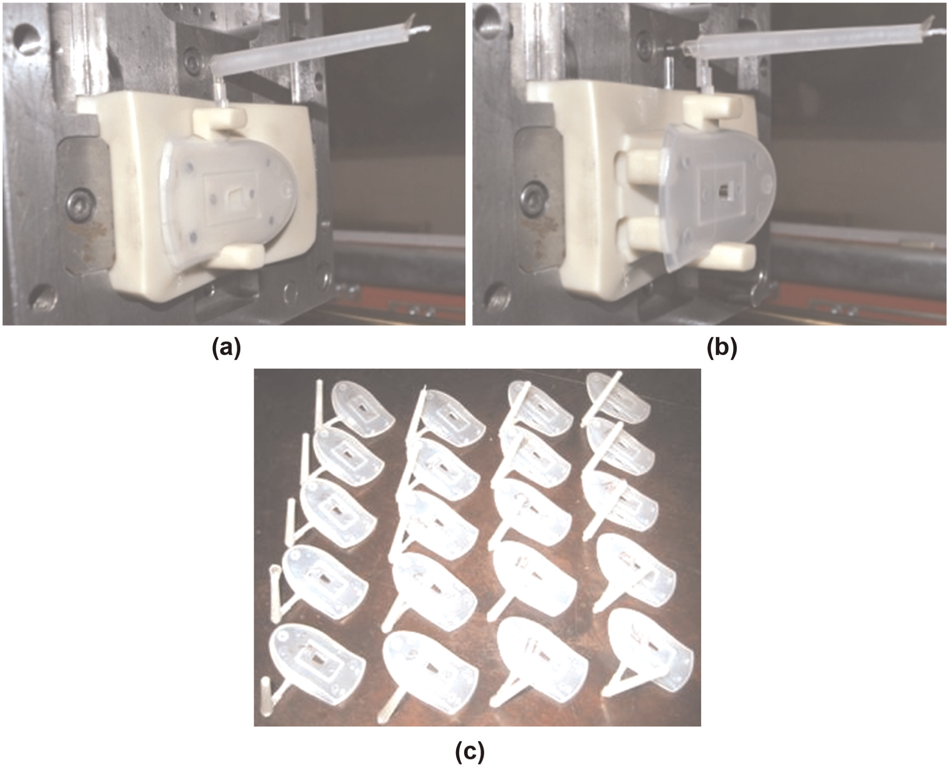
(a) Opening the mold, (b) extracting the molding and (c) injected prototypes.
The fit procedure worked satisfactorily and the final clearance measured after machining was 0.03 mm for the internal slide and 0.04 mm for the external one. This clearance allowed the slide to work satisfactorily, and the wavy profile (peaks and valleys) reported above was not sufficient to produce polymer flash during injection (see Figure 13). Indeed, the only marks observed in the molding were the traditional slide lines (Figure 13(a)–(c)). This was a considerable improvement on the material flashes reported in a previous work. 5
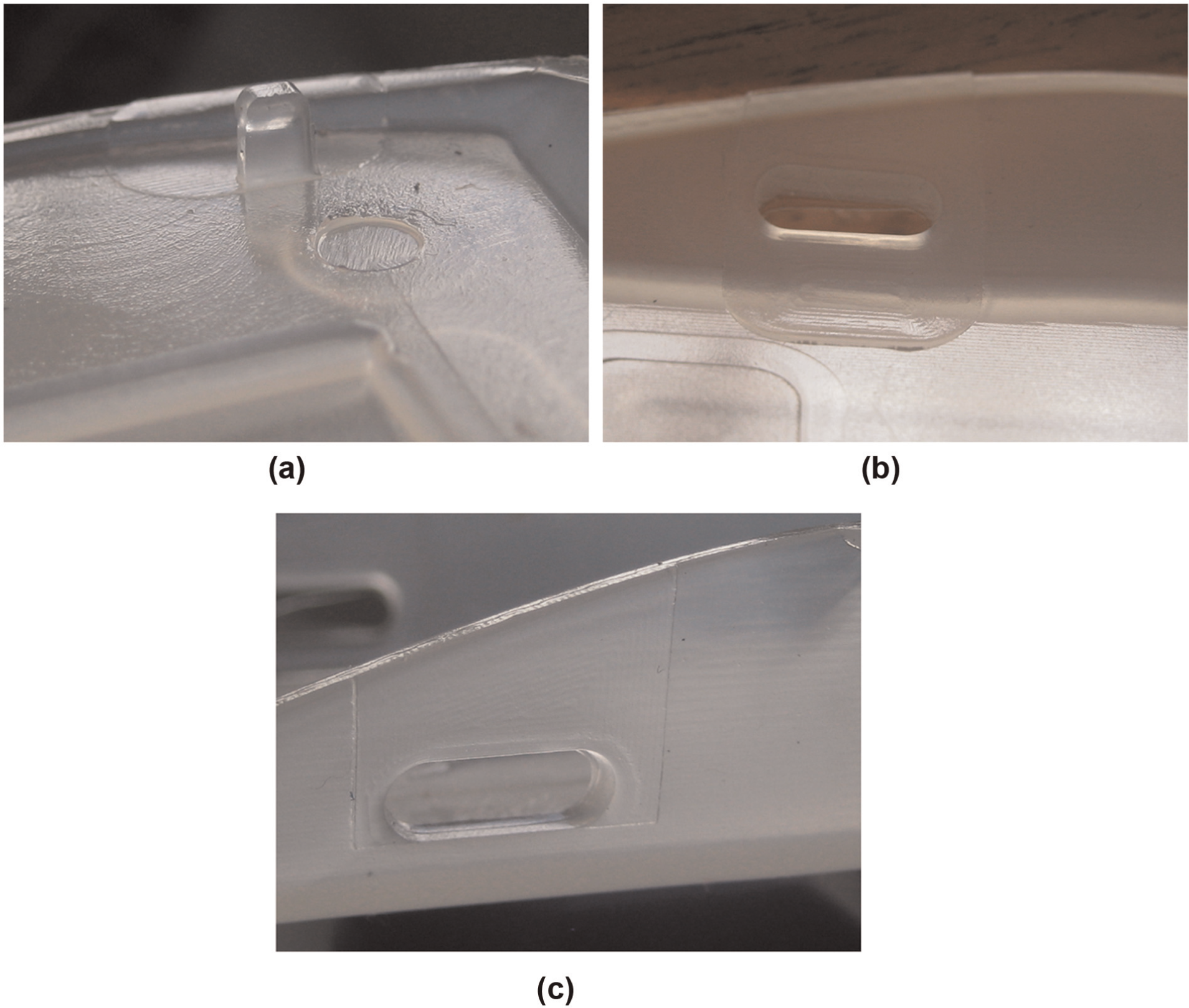
A good fit between the slides and their beds leaving only small marks on the surfaces of the molding (a: internal slide; b: external slide—option 1 and c: external slide option 2).
Regarding the issue related to the forced manual extraction of the internal slides, it was observed that for this specific case, they could be removed immediately after the ejection stage by applying slight pressure to the clips (Figure 14(a) and (b)). No apparent damage was caused to the molding or slides for the number of injections performed in this work.
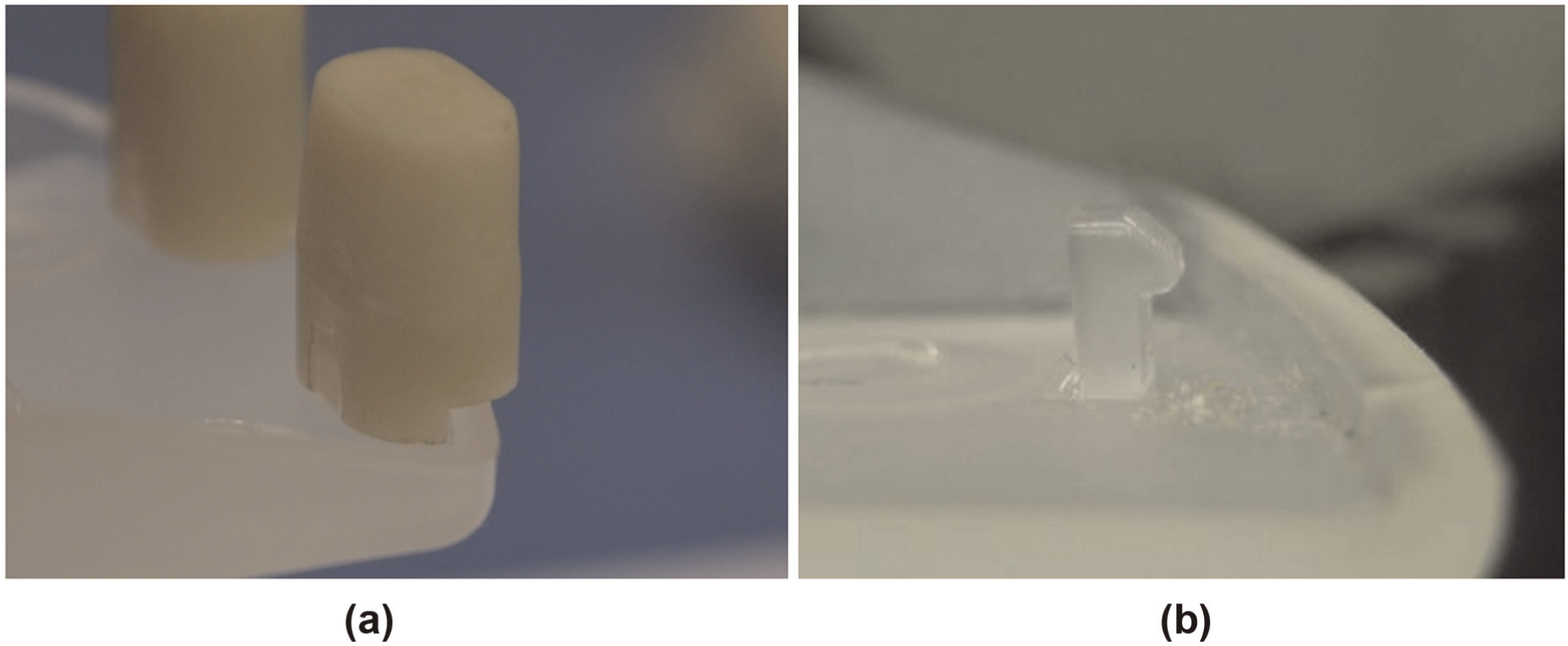
(a) Internal slides still in place after ejection and (b) one of the clips after the slide had been extracted.
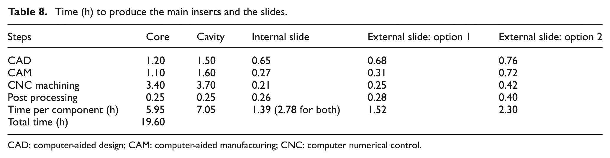
In relation to the two design options for the external slides, both exhibited the same behavior during injection. As can be observed in Figure 13(a) and (b), only the marks on the molding surfaces were different. In the case of option 1, a slide line starts from the bottom of the molding, while in option 2, it starts from the oblong slot. However, during the design and manufacture of these two options, some points emerged. First, the geometry of option 1 was easier to extract in the CAD, requiring just one cut command and therefore less modeling time (see Table 8). During post processing of the rough region, option 1 was easier to handle than option 2 because the latter had an important flat surface (see Figure 9(c)) close to the rough region, which required more attention during post processing. In addition, the corresponding matching surface in the slide bed required a more detailed CNC finishing strategy (more programming and machining time).
Time (h) to produce the main inserts and the slides.
CAD: computer-aided design; CAM: computer-aided manufacturing; CNC: computer numerical control.
Another advantage of the fit procedure was the considerable reduction in the time needed for the post-processing stage. In the previous study, 5 the average time to find the right fit for a removable slide was 0.61 h, compared with 0.27 h for the internal slides and option 1 in the present study. This represents a time saving of around 56% in this step, which can be attributed to the fact that there was no manual work to be done on the important slide surfaces, so that a less skilled operator could do the job.
Conclusion
This article reports the findings of a study of the use of slides in prototype tooling. Recommendations for producing internal and external slides (internal pins and side-cores) are made, accuracy issues related to the manufacturing systems are highlighted and a procedure for achieving adequate clearance for slides without a manual post-processing step is proposed.
Analysis of cutter runout for the machining system showed that prediction of the offset value in the CNC program so as to obtain the right fit the first time is not an easy task. Each machining system (spindle, tool holder and cutter) has its own characteristics. The engineering solution to achieve a satisfactory slide fit directly after CNC machining proved successful and can be considered simple to use as the fit is adjusted by quickly repeating the CNC finishing steps and decreasing the cutter radius until a satisfactory fit is obtained. This procedure is not only faster but also avoids the need for manual skills during post processing of the slides, which was the source of some material flash during the injection process in our previous work.
The internal and external slides proposed for this multi-piece mold worked satisfactorily. The case study showed that a similar design and manufacturing approach can be applied to IU and EU features. Both the internal and external slides were extracted as expected during the injection process. It was also observed that for the test part used here, there was no need to use ejector pins to extract the slides, and that this task could therefore be assigned to the molding. The results also showed that for this particular test part, which used PP, the slide could be withdrawn from the molding by forcing it out. This could be useful when the part geometry requires that the slide be removed in a direction in which there is an obstacle.
The design and manufacturing suggestions presented here can also be applied in cases where the AM technology used is not accurate enough to manufacture the inserts. The accuracy issues that may arise when attempting to achieve a satisfactory slide fit using this technology can be overcome by leaving this step to CNC machining with the aid of the fit procedure proposed here. This procedure could also be used with metallic materials, such as aluminum or zinc alloy. However, a specific study should be carried out to determine how the procedure performs with these materials and whether any changes are required.
Footnotes
Acknowledgements
The authors would like to thank the National Council for Scientific and Technological Development (CNPq, Brazil) and Huntsman Brazil for providing technical and financial assistance for this study.
Declaration of conflicting interests
The authors declare that there is no conflict of interest.
Funding
This research received no specific grant from any funding agency in the public, commercial, or not-for-profit sectors.