
Abstract
A high-speed length measuring system for mobile and large-scale cylinder workpiece was designed and constructed. This measuring system is characterized by two stationary laser scanning systems placed on two sides of workpiece responsible for the acquisition of points of key parts. Meanwhile, for making the measuring process faster and more flexible, the virtual measurement datum planes play an important role, and are step-by-step generated according to various features of measured surface in an online virtual inspection environment. Moreover, modeling and identification of end point of workpiece are established based on height variations in its nearest neighborhood. The three-dimensional dynamic length measurement data are then obtained by calculating the displacement between end point and corresponding datum plane. The prototypal system has been tested on different real cases with several typical cylinder workpieces (length 1000 ± 20 mm, diameter 50 ± 25 mm). Compared with the measurement results of coordinate measuring machine, the root-mean-square errors of the measurement data are smaller than 0.035 mm. The system measurement uncertainty is better than ±0.040 mm. The measuring time is less than 2 s. The proposed measuring system features high automation and high efficiency, and is most promising for on-machine applications in large geometric dimensional measurement.
Keywords
Introduction
In industrial manufacturing processes, the geometrical dimensional inspection of large-scale workpieces is critical and challenging, and is directly associated with subsequent assembly and terminal product quality.1,2 The length measurement of large-scale workpieces is one of the crucial fundamental quantities to ensure their conformity to design specifications serving a range of industries, from automotive and aerospace industries to house applications.3,4 Consequently, the broad diversity of large-scale metrology applications, involving numerous manufacturing areas, brings out the interest in designing innovative and efficient measuring systems for large-scale workpieces. Meanwhile, this ever-increasing demand for faster and more accurate dimensional measurements of large-scale workpiece has already initiated the search for new solutions in large-scale measuring system, coupled with an incessant development of the existing ones, but a constant need for simple, safe, low-cost and effective solutions that would satisfy the modern industrial requirements still persists.
In the production line, conventional length measurements are via coordinate measuring machine (CMM) equipped with touch-trigger probes.5,6 Although this method provides high precision, its inherent slow speed and specialized operators are very difficult to satisfy the measurement requirements. To solve this problem, a new promising trend in the field of dimensional metrology is to integrate multi-type of noncontact sensors into the CMM, such as moiré topography projectors, image sensors and structured-light sensors, which are employed to get more accurate and reliable information only on key parts of target because of the restriction of measurement efficiency.7–10 But till now, there are no efficient measuring systems, which can be widespread for large-scale workpiece geometrical inspection with high accuracy and flexibility. Moiré topography projectors have the advantages of high measurement efficiency and large depth of field in detecting large-scale workpiece, and they are widely used for some simple-structured large parts but cannot identify the fine structure of key parts owing to their working principle.11,12 Image sensors are mainly exploited in machine vision for online dimensions measurement of some kinds of large-scale workpieces in mechanical industry, and they have a high geometrical resolution but are slow and deficient in terms of computation source. 13 Moreover, those sensors have to suffer from geometric or radiometric constraint problems. 14
Recently, within the family of industrial vision-based sensors, the development of Light-Structured-Based systems (LSB) based on the laser triangulation to obtain three-dimensional (3D) measurement model has gained abundant attention and popularity due to their price affordability, relative reliability, high precision and fast shape acquisition in a reasonable duration of time.15,16 In particular, nowadays, laser line scanning 3D digitizing system is the most commonly utilized in online traditional large-scale dimensional metrology. Associated to high-speed, high-resolution and noncontact nature, laser scanning technology has numerous applications in civil engineering, manufacturing, defense and environment studies for sensing and imaging of mobile objects and dynamic process.17–20 In addition, in the engine production process, laser scanning systems have been mounted on different platforms, that is, computer numerically controlled (CNC) milling machines, mechanical or robotic arms and CMMs.21–23
This article aims at studying and developing an innovative approach using 3D laser scanners for online automatic length measurement of similar regular large-scale workpieces. In the design system, in order to harmonize the desired high precision with the low time consumption and costs, automation and simplification of whole measuring process are imperative using a suitable method. Two difficulties are encountered in establishing the 3D displacement field for mobile and large two-dimensional (2D) cylinder workpieces. First, the datum plane is required to real-time adapt to the features of measured surface of workpiece. Second, the end points of workpiece to be determined may not be distributed on the same plane so that it is difficult to describe the measuring system by a unified accurate mode in 3D space.
The growing application of virtual datum models may support the achievement of the first sight as they not only characterize geometrical information but also assemble features, parameters and rules of formalizing the design knowledge.24–27 A virtual measurement datum plane (VMDP) can be step-by-step generated according to the features of measured surface of target. Also, it is convenient to import a 3D measurement model containing the specific requirements into a virtual inspection environment. On the other hand, according to the laser triangulation principle, light stripes are distorted by the height variation. 28 Hence, height fluctuation in the nearest neighborhood of end point can serve as a criterion to locate its position.
In practice, error self-correction mode is an imperative part of improving the measurement accuracy online.29,30 Therefore, identifying and analyzing all the possible errors linked to the measurement process are fully considered. The influence of the errors which may be enclosed in the process of producing VMDP can be eliminated by the use of 2D error separation method. 31 Moreover, it is also important to calibrate the measuring system by a cylinder standard workpiece, which would allow for improving the measurement control processes, as well as to allow for system error compensation.
The remainder of the article is organized as follows. First, 3D virtual measuring mode that is based on VMDP and 2D error correct techniques is developed in section “3D virtual measuring mode.” Second, in section “Establishment of 3D displacement field,” modeling and identification of the position of end points of workpiece are discussed, and 3D displacement field is established. Then, section “Experiments” presents the measuring system set-up used to test the proposed approach in detail and demonstrates experiment results and analysis. Finally, conclusions are given in section “Conclusion.”
3D virtual measuring mode
The considered measuring system consists of two laser scanners LJ-G030 (Keyence Co. in Japan) with a standoff of 30 mm, a depth of field of 20 mm and a scan width of 25 mm. They achieve the highest sampling speed less than 5 ms. The principle of those scanners is based on active triangulation (see Figure 1), whose resolutions are 5 and 1 µm in the X-axis and Z-axis, respectively.
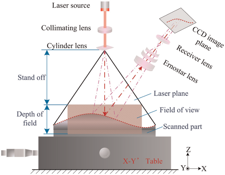
The principle diagram of laser scanning.
Measurement procedure
As shown in Figure 1, the laser plane, whose centerline is always perpendicular to the measured surface, is reflected on the surface of the scanned part. Then, a line is generated at the intersection of the laser plane and measured surface. The line segment in the field of view with a relatively dense point cloud (about 800 digitized points) is captured by the scanning system.
In the 3D measuring system, two stationary scanning systems respectively arranged to place on both ends of large-scale workpiece are to capture only a small part of its top surface (Figure 2). The linear movement of the workpiece along the Y-axis allows to obtain two-point clouds (two independent sets of scanning lines) corresponding to the considered surfaces.
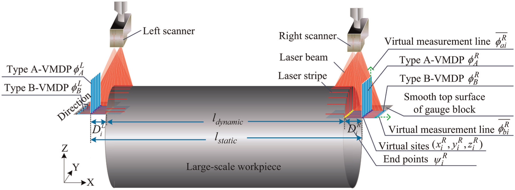
Schematic diagram of constructing 3D measuring system.
Establishment of VMDP
The idea of the proposed VMDP set-up is straightforward: (1) VMDP should be step-by-step dynamically synthesized by producing new virtual measurement line in the online inspection process in terms of demand; (2) each virtual measurement line is independent and has its own virtual registered site; (3) if points on the workpiece are measured by laser scanning system, the absolute position of these points should be independent of the relative position of the scanner to the VMDP.
As stated previously, the scanning system is stable in time. Thus, it is possible to generate virtual measurement datum line closely linked with virtual registered sites that may be reproduced in another repeated measurement. The virtual sites should be registered in such a way that they cover evenly the whole measured surface of workpiece. According to specific demands of measuring system, virtual datum planes are classified into two types (Figure 2). Type A-VMDP (
As a basis for creating this mode, a Matrix Method, developed by Mailhe et al.,
24
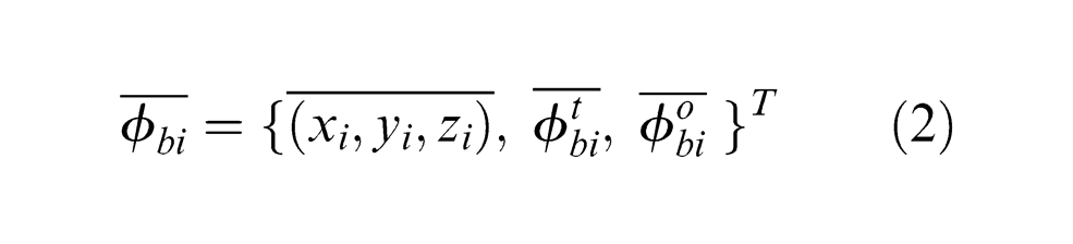
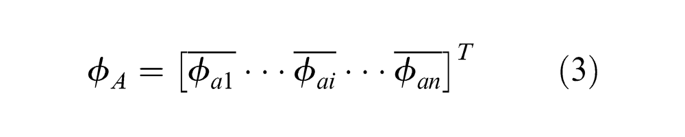
is efficiently implemented in establishing large-scale VMDP. The virtual measurement lines of Type A-VMDP and Type B-VMDP are characterized by the vectors
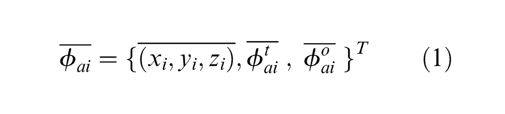
where the first component
During the construction phase, a connection between the different virtual measurement datum lines should be realized. In the case of Type A-VMDP, in order to reduce the operation time, a linear interpolation is actually performed to online generate a static plane containing the entire virtual registered sites. Thus, the Type A-VMDP can be described by the following formula
To the contrary, as in the case of Type B-VMDP, a corresponding height variation along the Z-axis between the neighboring basis vectors
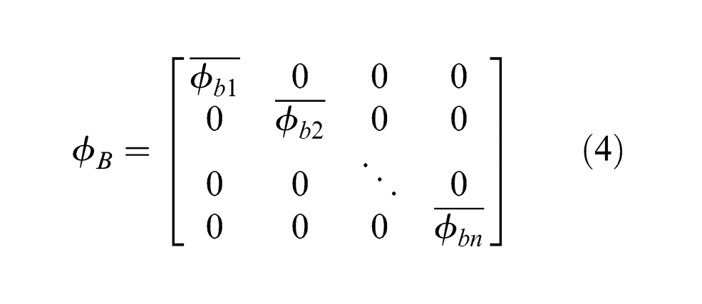
where
In practice, the establishment of VMDPs can be generally divided into four steps. As presented in Figure 2, primitive point clouds representing a measured surface are online obtained by laser scanning devices. The first step is to identify the smooth top surface of gauge block based on its continuous nonvariant height feature. Next, for facility and stability, a virtual site is registered on this regulated surface and keeps a fixed distance relative to the stationary laser scanning coordinate. Then, the virtual measurement lines
2D error correction mode
In order to promote the accuracy of the measurement results, it is essential to identify and analyze all the possible errors linked to the measurement process, and to online self-correct the systematic errors by a simple and effective solution. To describe this system, Systematic Errors Function (SEF) has been used and is defined as follows. First, the error of scanner is dependent on the relative positioning

where
The variations of the first three parameters on the right of equation (5) have a considerable influence on the measurement errors. However, developing a theoretical model to determine those parameters during the calibration phase is difficult and impossible. As it was already mentioned, while describing VMDP in the local scanning system, the position of arbitrary sampling point in relation to the VMDP is independent. In such a case, it is possible and feasible to separate systematic errors into two orthogonal components
If a local scanning system is specified in a two-dimensional space
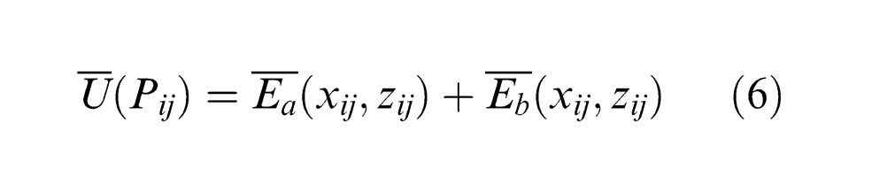
where
According to the basic vectors for constructing the VMDP mentioned in section “Establishment of virtual measurement datum plane,” the final form of vector
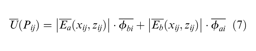
Similarly, the vector field of systematic errors at its adjacent position could be obtained, as shown in equation (8)
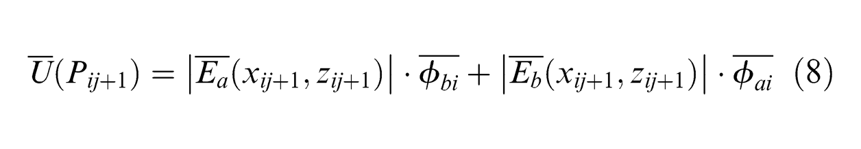
The difference between equations (7) and (8) can be represented by the following equation
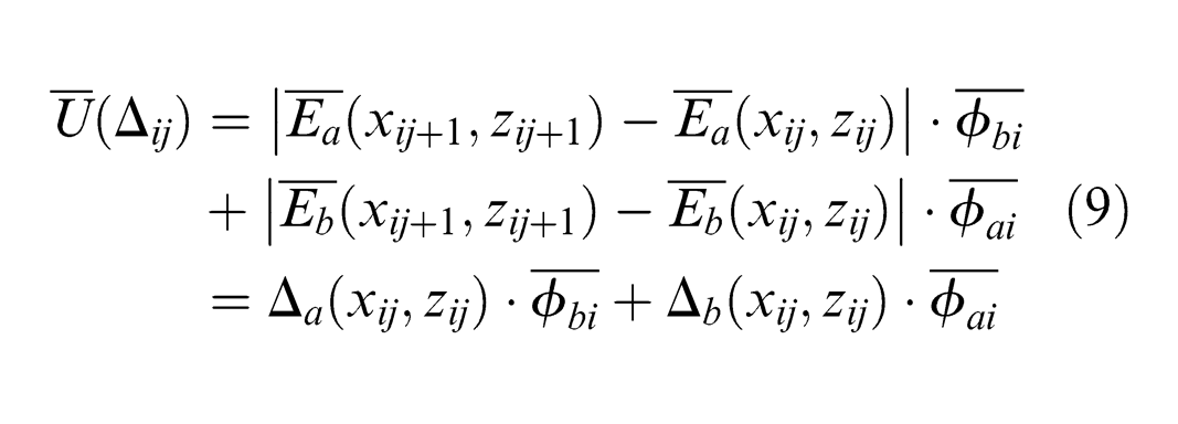
where
Equation (9) indicates that if the correction coefficients
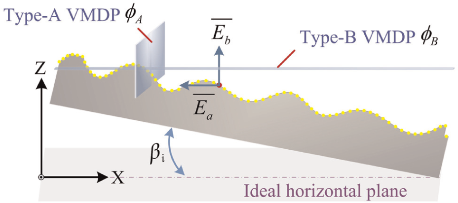
2D error correction mode.
Establishment of 3D displacement field
Modeling and identification of the position of end points of workpiece
Two gauge blocks with flat ends and smooth top surface are attached wholly to the two ends of workpiece, respectively (see Figure 2), in order to develop a module responsible for quickly and reliably determining the position of end points independent of the quality of the measured surface of workpiece. This module concentrates on continuous height variations in the nearest neighborhood of end point in a 2D space. To model those end points, several typical height features of end points have been investigated to constitute prototypes that facilitate the identification procedure (Figure 4).
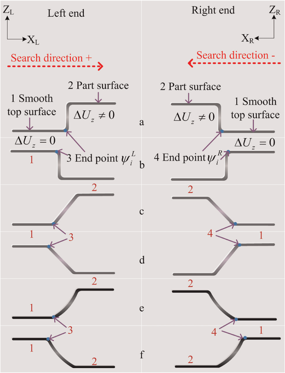
Different prototypes of the position of end point of workpiece with flat end (a) and (b), inclined end (c) and (d), curved end (e) and (f), and higher ((a), (c) and (e)) and lower ((b), (d) and (f)) than gauge block.
As shown in Figure 4, in the case of the whole smooth top surface of gauge block, the height gradients along the X-axis are stable and remain about zero all the time. In contrast, as in the case of part surface in the nearest neighborhood of end points, the height gradients seem particularly changeable and exhibit no obvious regular rules. Then, in the prescribed 2D space
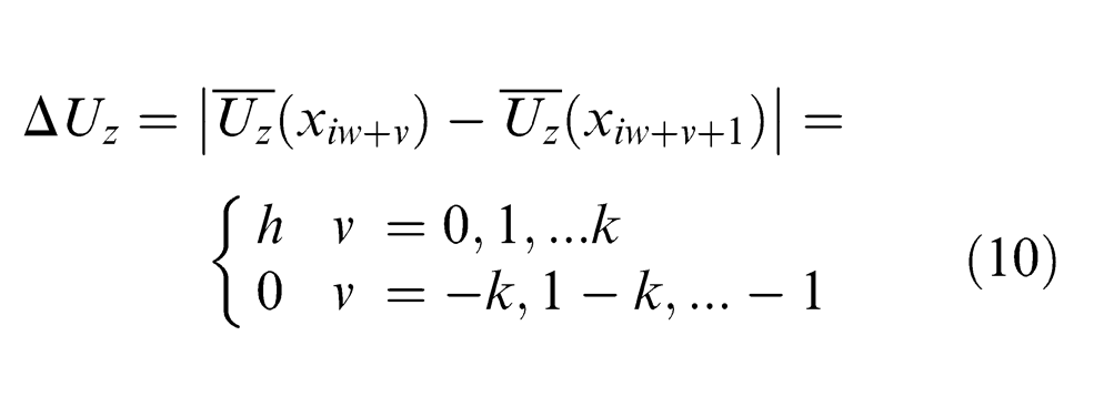
where
From equation (10), height variation in the nearest neighborhood of end point can be considered as a criterion to distinguish the end point from the measured surface of workpiece. In such a situation, it is easy to locate the position of end point along the X-axis direction using less cost and lesser time consumption in an inspection process.
In order to make the model complete, another important problem must be investigated in addition to the factor analysis of location accuracy that has been achieved with preceding methodology. In an ideal case, it is conventional to identify the height feature to determine where the end points actually lie in a virtual inspection environment. But this determination may be potentially influenced by several factors such as subtle changes in optical properties according to the changeable morphology of end plane, the reflectivity from the side wall of gauge. Figure 5 shows the data acquired near the intersection of the side wall of gauge and an end plane. Notice that if the laser beam is inside the intersection zone, some portion of the converging beam strikes to the surface of end plane and is reflected to the side wall of gauge. The light scattered from the side wall is then sensed and formed the image by the scanner. The located position of end point is therefore not consistent with predicted value implied by the identified mode sufficiently, thus producing a large error with respect to true end point. It is also noted that the deeper and more complicated the intersection zone, the more significant the impact of location error.
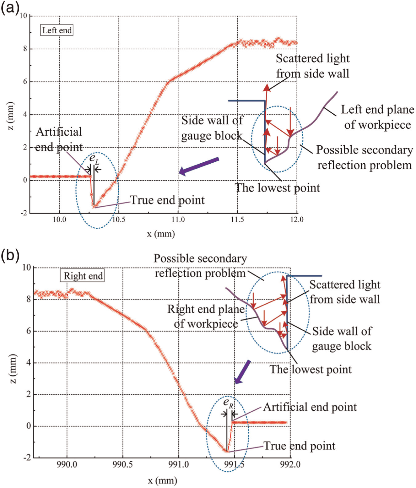
Influence of the possible secondary reflection problem on the localization accuracy of end points.
From above analysis, it comes out that secondary reflection in the intersection zone has considerable influence on distinguishing the position of end point and this problem nevertheless exists in many practical applications. Hence, an attempt to diminish the effect of multiple reflection lights is necessary to meet online measurement requirements. As a first step, a simple four-point moving average filter is applied to analyze the measurement data in this work. The main advantage of this filter lies in the fact that it does not only effectively reduce the impact of random noise, but also highlights the middle-term fluctuation, as well as suffers from a small delay that may lead to potentially large error in end-point location. 32 In the next step, in the case of previously identified mode, once the artificial point has been successfully localized, the search procedure continues until finding the closest point that has a minimal value along the Z-axis in its neighborhood (see Figure 5). Thus, instead of artificial point, the novel localized point can greatly solve the possible secondary reflection problem in the intersection zone by a simple yet robust way, and maintain a reasonably small location error. On the other hand, it should be pointed out that a calibrated workpiece with the same properties such as material, color, reflectivity, and so on should be implemented to further improve the location precision.
Finally, by combining equations (1) and (3), the distance relationship
Displacement field calculation
The coordinate relationship between the global workpiece positioning system (GWPS) and the scanning systems must be established. According to the system described in section “Measurement procedure,” two scanning systems are arranged in a linearly independent way. In this case, the laser planes
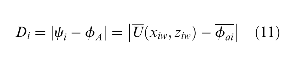
According to equation (11), the displacement between the end point and its corresponding Type A-VMDP can be calculated, and then two displacement sets
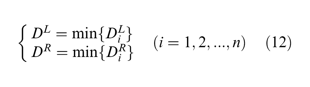
where
Consequently, the dynamic length of mobile and large-scale workpiece can be obtained by
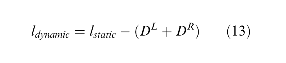
Additionally, a workpiece of the same type, already measured by CMM, is chosen to calibrate the distance
Experiments
For the purpose of high-speed automatic length measurement of a mobile and large-scale workpiece, the resources in the whole measurement system, including two scanning systems, the precision carriage slide structure, the cross-slide structure, the stepper motor driving system, the pneumatic driving system, gauge block, V-blocks and the computer used for control operations and data processing, were integrated technically, as shown in Figure 6. The scanning systems and gauge block have been described above in sections “Measurement procedure” and “Modeling and identification of the position of end points of workpiece,” respectively. The carriage slide is driven by stepper motor and has a maximum travel range of 2100 mm. The cross-slide is driven by pneumatic equipment and has a maximum travel range of 400 mm. The workpiece was supported by two V-blocks and fixed close to the Bessel points in order to minimize the influence of bending on the length measurements. An automatic measurement program, written in VC++6.0 and ran on a personal computer (PC) with an Intel Core i5 Duo CPU 2.26 GHz and 2GB RAM, was developed to control the whole measuring course, and to process the measured data of the scanning systems. The step-by-step trigger event was performed to control the scanning systems, and the duration of event was about 50 ms.
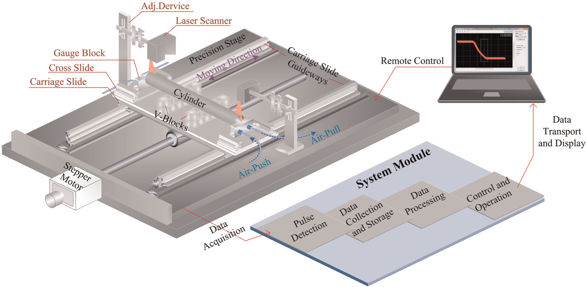
Schematic illustration of the developed length measurement system by integrating two scanners.
A representative cylinder workpiece (diameter 50.046 mm and length 1000.050 mm) with two flat ends was selected to calibrate the distance
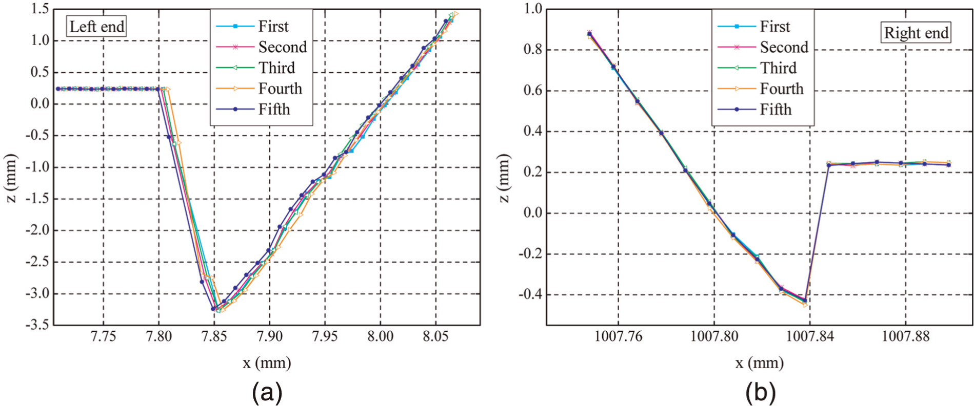
Five times repeated 2D measurement data at
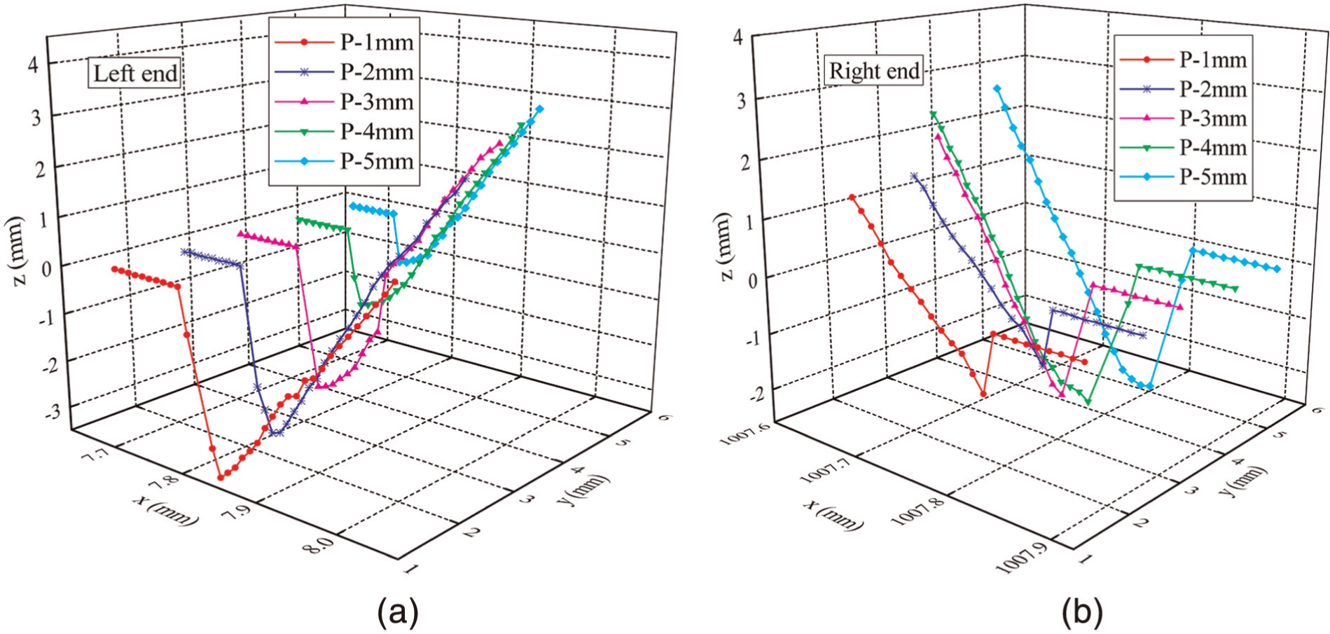
3D digitized data for five different positions in the intersection zone (at
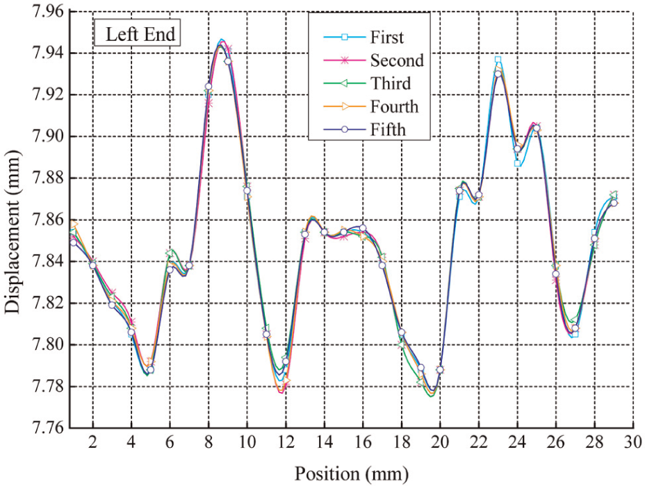
Results of displacement measurements (left end of calibrated workpiece).
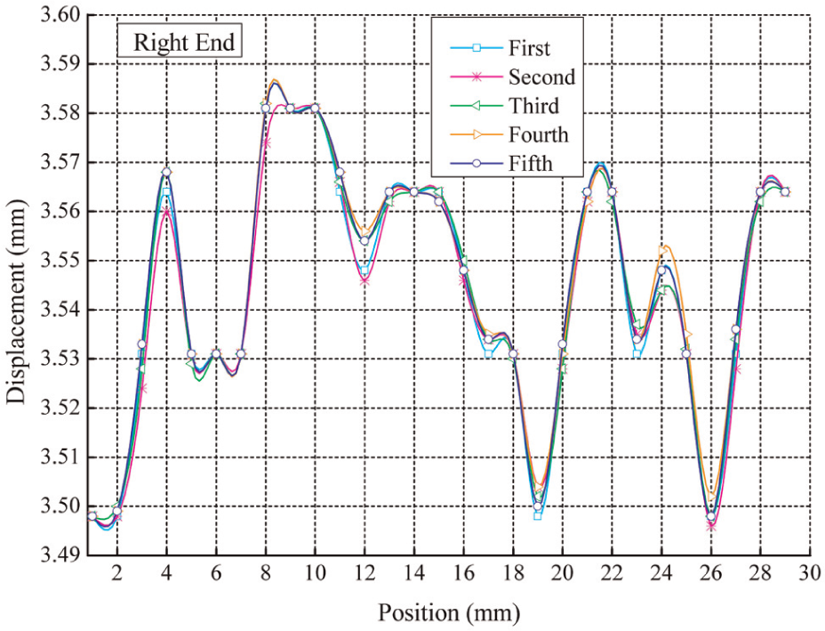
Results of displacement measurements (right end of calibrated workpiece).
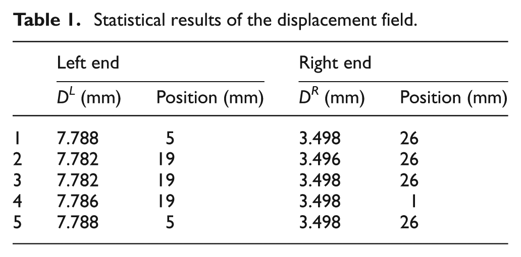
Statistical results of the displacement field.
For the verification of length measurements, four other typical cylinder workpieces (sequentially represented by WT1, WT2, WT3 and WT4) with same material were chosen and measured under this environmental condition, as listed in Table 2. Comparative measurements of four different workpieces between the developed system and the CMM have been carried out and are shown in Figure 11. Table 3 presents the statistical results of the length measurement data. It was observed that the repeated data of WT 2 and WT 4 had a wider range of fluctuation and dispersion than those of WT 1 and WT 3. All root-mean-square errors (RMSE) were better than 0.030 mm. The result of the maximum deviation from standard value measured by CMM was about 0.060 mm. The measuring time was less than 2 s.
All the parameters of cylinder workpieces measured by CMM.
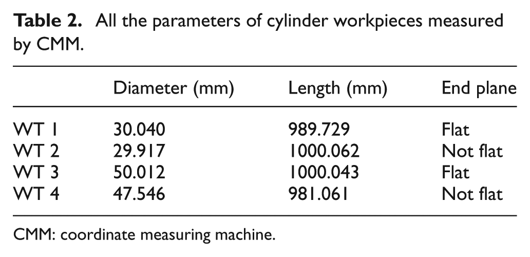
CMM: coordinate measuring machine.
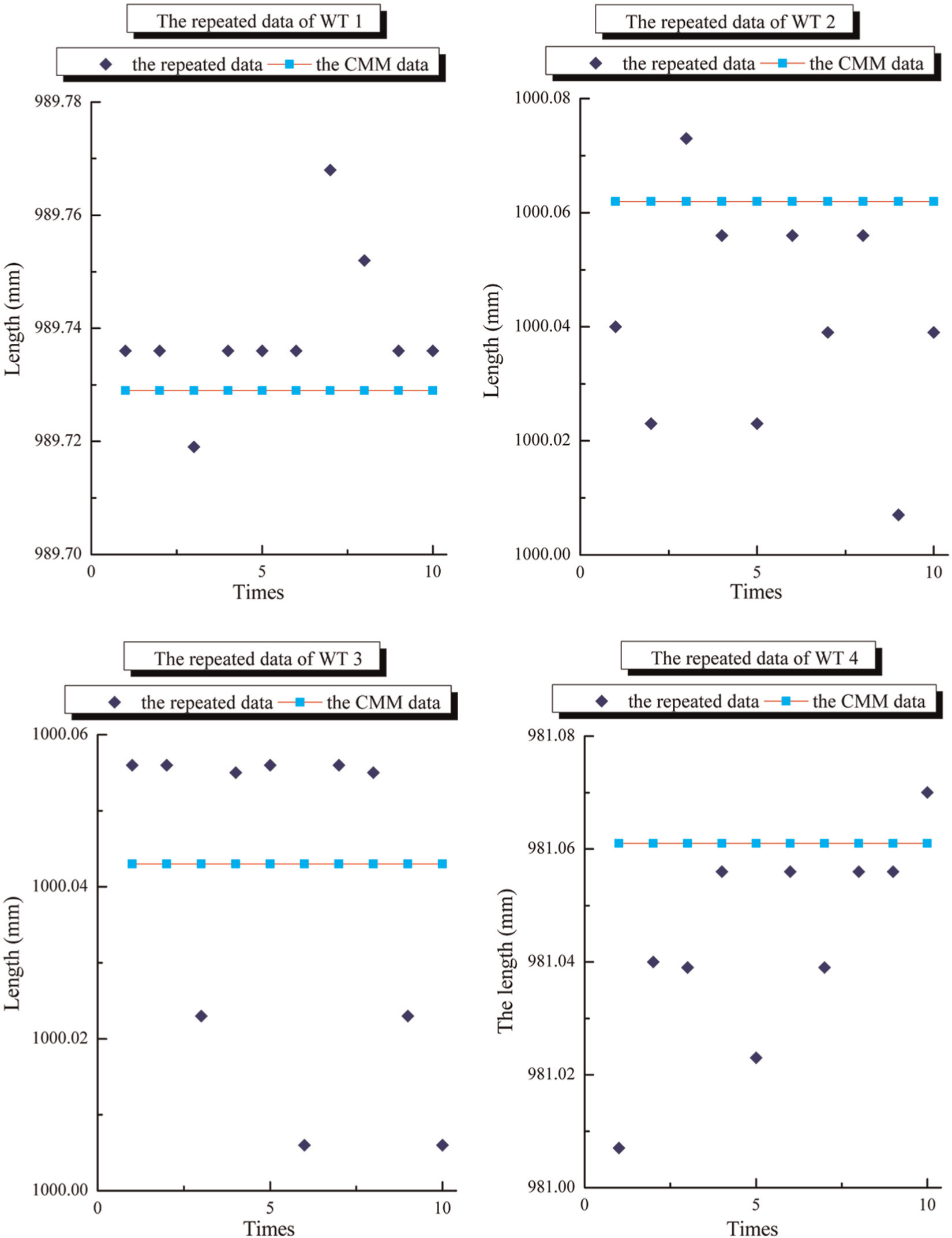
A total of 10 repetitive length measurement results of WT 1, WT 2, WT 3 and WT 4.
Statistical results of the length measurement data.
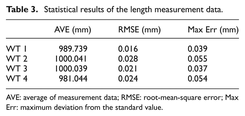
AVE: average of measurement data; RMSE: root-mean-square error; Max Err: maximum deviation from the standard value.
In addition, for each measurement, the standard uncertainty should be taken into account by the classical method that is in accordance with the ISO Guide to the Expression of Uncertainty of Measurement (GUM) and ISO 14253. Determination of the measurement uncertainty is a very complex task because of many uncertainty factors involved in this system which can be divided into the following: the scanning system, calibrated workpiece, the system mechanism, the illumination, sampling strategy and the measurement algorithm. In this experimental phase, sampling strategy as a major uncertainty element was investigated.
Generally stated, the more the end points are obtained accurately, the smaller the length measurement uncertainty will be. In this case, a uniform sampling interval along the Y-axis is certainly proportional to the speed of workpiece. Figure 12 shows the comparisons of the results of length measurements with corresponding standard uncertainties at the uniform speed of 20 and 40 mm/s, respectively. It was noted that the standard uncertainties were becoming greater with accelerated speed that resulted in the loss of specified end points. Therefore, a reasonable moving speed of workpiece and an optimized measurement algorithm should be considered and are consistent with the recommendations of online measurement.
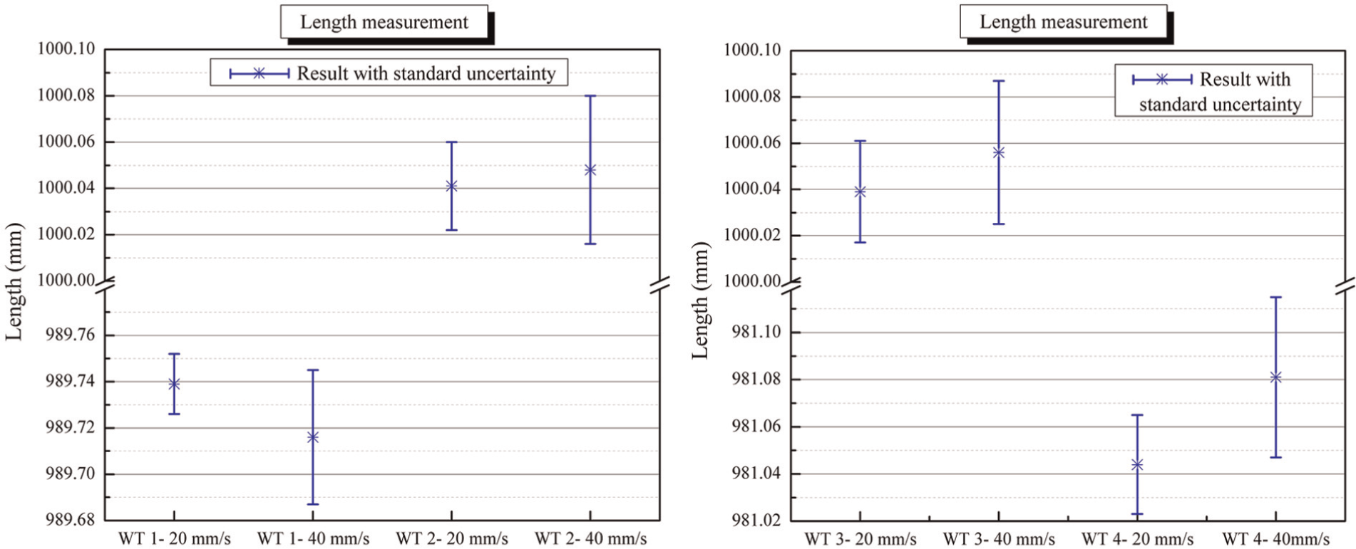
Comparisons of the results of length measurements with corresponding standard uncertainty at the uniform speed of 20 and 40 mm/s, respectively.
Conclusion
This article presents a simple, high-speed length measurement system for mobile and large-scale 2D cylinder workpiece based on 3D laser scanning technologies. First, two scanning systems placed on the two ends of workpiece grab point clouds of its key parts. Second, according to the provided features of measured surface, the VMDPs are step-by-step generated. Third, a 2D error self-correct mode is developed to reduce the influence of systematic errors. Then, a 3D virtual measuring mode is built in a virtual inspection environment. Meanwhile, modeling and identification of the position of end points of workpiece are designed by a simple yet effective method in this 3D virtual measuring environment. Finally, the 3D dynamic length measurement data of workpiece are obtained by calculating the displacement between the end point and its corresponding datum plane. The performance tests on different real cases with several representative cylinder workpieces (length 1000 ± 20 mm and diameter 50 ± 25 mm) have been carried out. Compared with the measurement results of CMM, the RMSE of the measurement data are smaller than 0.035 mm, and the maximum deviation from standard value is less than 0.060 mm. The system measurement uncertainty is better than ±0.040 mm and the whole measuring process takes less than 2 s. The proposed length measuring system features high automation and high efficiency, and is most promising for on-machine applications in large geometric dimensional measurement.
Footnotes
Declaration of conflicting interests
The authors declare that there is no conflict of interest.
Funding
Our work has been supported by the Key Project of Chinese Ministry of Education (Grant No. 108174) and the Chongqing Municipal Natural Science Foundation of China (Grant No. CSTC2008BB3169).