
Abstract
Horizontal welding plays an important role in manufacture of large and heavy aluminium alloy structures. But there are many problems such as bad weld formation, porosity and low efficiency. Variable polarity plasma arc welding is a low-defect and high-efficiency welding technology, but it has difficulty in horizontal position. The maximum weldable thickness is less than 6.4 mm in single-pass weld. The soft plasma arc was proposed in this article. Horizontal welding of aluminium alloy plates with 8 mm thickness was realized successfully. The joint was free of defects and had excellent mechanical properties. This is a breakthrough in single-pass horizontal welding. Moreover, the characteristic of the soft plasma arc was studied in detail and the fluid flow in weld backside was observed. Finally, the forming mechanism of a stale weld pool was discussed. Results indicated that the arc pressure with the soft plasma arc was lower than that with the ordinary plasma arc. The fluid flow was asymmetric in horizontal position. The forming of a keyhole was realized by the bridging of the molten metals in the upper and lower sides. The weld pool was stable with the soft plasma arc because the maximum diameter of keyhole was bigger than that with the ordinary plasma arc.
Introduction
Nowadays, more and more aluminium alloys are chosen as structural materials of aircrafts, vehicles, ships, pressure vessels and so on due to their excellent corrosion resistance and high strength. 1 In the manufacture of large and heavy aluminium alloy structures that cannot be inverted easily, horizontal welding on vertical surface (2G) is needed. For instance, in the fabrication of propellant tanks of heavy lift launch vehicles which are important for exploration of deep space, horizontal welding of aluminium alloys is needed for the large diameter and length of the propellant tank. 2 So it is important to study horizontal welding of aluminium alloys.
It has been commonly believed that horizontal welding is difficult because of the influence of the gravity on molten pool. The major problems of horizontal welding are low welding efficiency and serious welding defects such as undercut, porosity, sag and overlap.3–7 Some researchers have studied the forming mechanism of welding defects. The buoyancy-induced flow and the sag of the molten pool are responsible for the weld asymmetry. 8 The undercut was caused by the slower flow velocity in the upper part of the weld pool. 9 The simulated results of Kumar and DebRoy 10 indicated that surface profile, welding penetration and cooling rate varied with welding positions. Many researchers have studied the methods to eliminate welding defects. These methods include reducing the heat input by controlling welding parameters or using pulse welding current, counteracting the gravity by using Lorentz force or surface tension and the method using rotating arc and so on.3,4,8,11
The published literatures of horizontal welding on aluminium alloys are very few. Horizontal welding of aluminium alloys is more difficult due to the physical and metallurgical characteristics of aluminium alloy itself. 12 The pores gather in the upper part of the joint and the welding efficiency is low.6,7 It is urgent to develop a proper horizontal welding technology with high quality and efficiency.
As a low defect welding process, variable polarity plasma arc welding (VPPAW) has advantages in welding aluminium alloy plates with medium thickness and has been realized for a number of critical applications, such as American international space station and space shuttle tank. 13 In vertical-up position which is the best welding position for VPPAW, single-pass weld with few pores and little angular distortion can be made in material thickness up to 16 mm. 14
The situation becomes bad in 2G position. Tomsic and Barhorst 14 found that aluminium alloy plates of thickness up to 6.4 mm (1/4 in) were readily welded by VPPAW in 2G position. Halmøy et al. 15 pointed out that the upper limit was a plate thickness of 6–7 mm. On 8- to 10-mm plate, the weld pool was unstable. Woodward et al. 16 carried out more than 60 trials in horizontal and flat position and their experimental results indicated that regular and repeatable molten pool could not be established.
The problem in horizontal welding is that the keyhole cannot close opportunely. This question also occurs in direct current keyhole PAW process. Some researchers have studied the methods to control the closure of the keyhole. Pulsed current PAW was invented to produce a keyhole in each peak current and close the keyhole in every base current. 17 Zhang and Liu 18 proposed a novel quasi-keyhole PAW technology which switches the current from the high peak current to the low base current after the keyhole was established. Wu et al. 19 also proposed a control system using a specially designed current waveform with two slow dropping substages of variable slopes to adjust the keyhole size in pulsed keyhole PAW. Li et al. 20 proposed a novel PAW mode called double-stage PAW which combined the keyhole and melt-in mode into a single welding procedure. In keyhole stage a partially penetrated keyhole was formed, and in the melt-in stage complete joint penetration was obtained finally. The visualization of the dynamic keyhole behaviour in controlled pulse keyhole PAW showed the dynamic variation of the keyhole in each pulse cycle: establishing, expanding, sustaining, contracting and closing. 21
In order to improve the stability of the keyhole in horizontal welding, the soft plasma arc was proposed in this article. The characteristic of the soft plasma arc was studied in detail. The shape of weld pool using the soft plasma arc was described. The fluid flow in weld backside was observed. Finally, the forming mechanism of a stable weld pool was discussed.
Experimental procedures
LTP400-VP welding power source made by Liburdi Engineering Limited, Canada, was used. The PAW torch was made by Thermacut, Inc. Timing control of all power and motion events was realized by Programmable Logic Controller in control box. The shielding gas and plasma gas both are argon controlled by gas flow controller. The welding system also includes a wire feeder and a cooling tank.
The base metal is 2014 aluminium alloy in T6 condition and its size is 200 mm × 120 mm × 8 mm. ER2319 was chosen as filler metal with 1.6 mm diameter. The chemical compositions of 2014 and ER2319 are given in Table 1. Two joint configurations, square groove and single ‘V’ groove (angle 60°, root face 5 mm) were used in the experiments. The surface of the plate was cleaned by acetone and the oxide film was removed by hand scraping before welding.
Chemical compositions of 2014 Al alloy and ER2319 (wt%).
Welding parameters are shown in Table 2. The preliminary trails include two parts named A and B for different welding speeds. The square groove was used in preliminary trails only. The other welding parameters such as electrode setback (3.8 mm), tungsten electrode diameter (4.8 mm), forward polarity time (20 ms), reverse polarity time (4 ms) and additional welding current (60 A) were kept constant. The additional welding current is the difference between the welding current’s value in direct current electrode positive (DCEP) stage and the value in direct current electrode negative (DCEN) stage.
Welding parameters of different experiments.
A high-speed camera with a frame rate of 3000 frames per second was used to observe the arc shape and the fluid flow of the weld pool. Plasma arc pressure profiles were obtained by moving the welding arc across a pressure tap on the chilled copper block. Metallographic specimens in cross section of the horizontal weld were polished and etched with Keller’s reagent. Tensile test was performed at room temperature.
Results
Preliminary trials
More than 50 trials were carried out in 2G position to verify the maximum weldable thickness described in literatures.14,15 The influence of primary welding process variables (plasma gas flow rate, welding current and welding speed) on weld formation was studied.
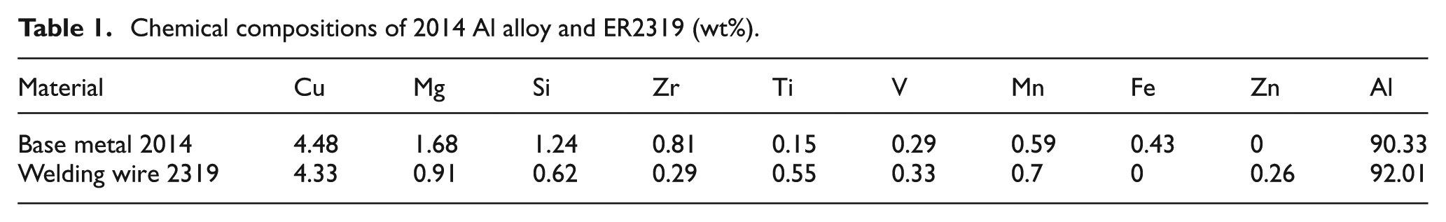
The operational window for different average currents and plasma gas flow rates at a constant welding speed 160 mm/min is shown in Figure 1(a). It was found that there were almost no appropriate welding parameters to obtain a keyhole weld. When the average current and the plasma gas flow rate were relatively low, the heat input and the momentum of plasma jet were not enough to make a keyhole, so partial penetration weld was formed. When the current and plasma gas flow rate increased, cutting happened.
Operational windows at different welding speeds and the appearances of typical welds: (a) welding speed 160 mm/min, (b) welding speed 200 mm/min, (c) partial penetration and (d) cutting.
The experiments at a welding speed 200 mm/min were carried out to further study the weld formation in 2G position. As shown in Figure 1(b), there was no operational zone for keyhole welding. The typical appearances of partial penetration and cutting are shown in Figure 1(c) and (d). The molten metal was flowed to the backside near the lower part in cutting process. So VPPAW of aluminium alloy plates with 8 mm thickness in keyhole mode could not be done in 2G position only controlled by welding parameters. This was in agreement with earlier published results.14,15
Change joint configuration
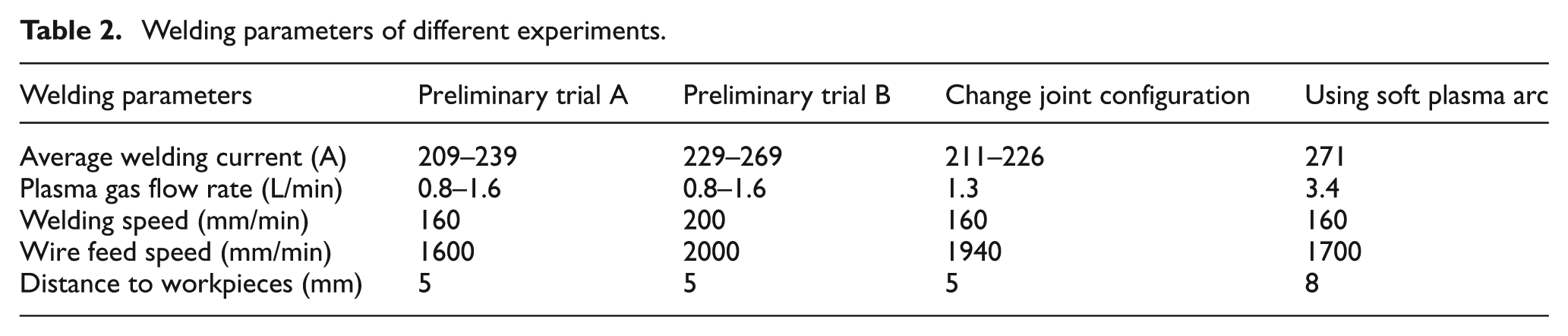
The weld pool was formed when the joint configuration was changed from square groove to single ‘V’ groove. The appearances of the horizontal weld with 8 mm thickness are shown in Figure 2(a) and (b). Although the keyhole could be established, the weld formation was bad and coarse with serious undercut. This may be caused by the unstable keyhole process. The forming mechanism of the weld pool with single ‘V’ groove will be explained in section ‘Discussion’.
The appearances of horizontal welds at different average welding currents: (a) front side, (b) backside, (c) 211 A, (d) 216 A, (e) 221 A and (f) 226 A.
The weld defects could not be eliminated by adjusting welding parameters. Appearances of horizontal joints at different average currents are shown in Figure 2(c)–(f). When the welding current was small, the undercut was serious in the backside. With the increase in welding current, the undercut in weld backside was not so serious, but the undercut in the front side became serious. The area of the undercut was measured as shown in Figure 3. The results indicated that higher welding current was beneficial for the weld formation in the backside. The reason will be explained in section ‘Discussion’. The effect of plasma gas flow rate on horizontal weld formation was similar to welding current. Cutting would happen when plasma gas flow rate was bigger. When the plasma gas flow rate was smaller, it was difficult to establish a keyhole and the weld formation was bad and coarse. So there were no appropriate welding parameters to obtain a good horizontal weld although the ‘V’ groove was used.
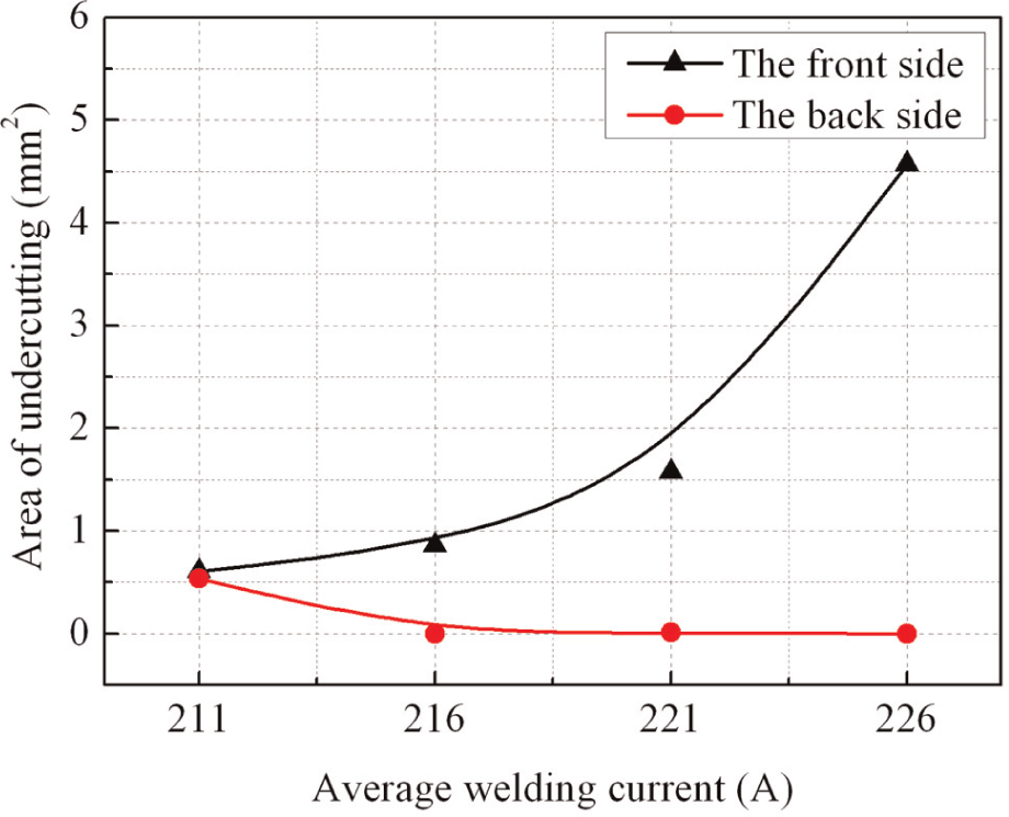
The area of undercut versus average welding current.
Using soft plasma arc
The problem in horizontal welding is that the keyhole cannot close opportunely. Even the keyhole can close, but the process is not stable and smooth. The quasi-keyhole technology or the double-stage PAW method may have a good solution of the problem. But the quasi-keyhole technology is mostly applied in pulse direct current welding process and the researches in VPPAW process are few. So the control of dynamic keyhole in VPPAW process may be a challenge. Moreover, the quasi-keyhole technology is little complex and requires sensors.
In order to improve the stability of keyhole, the soft plasma arc was proposed in this article. Theory foundation of this idea is the force balance of the weld pool which will be discussed in section ‘Discussion’.
The soft plasma arc was obtained by using the special nozzle with three orifices. The special nozzle shown in Figure 4 was machined by us based on the ordinary nozzle.
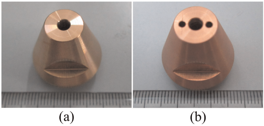
The photographs of (a) the ordinary nozzle and (b) the special nozzle.
Although the decrease in the plasma gas flow rate can reduce the arc pressure, there is no an adequate interval for adjustment. The plasma gas flow rate used in the above was 1.3 L/min, and when the plasma gas flow rate was less than 1 L/min the keyhole could not be formed. Changing electrode setback can also reduce the arc pressure. But when the arc pressure was low, electrode setback was less than 1 mm and the keyhole was difficult to obtain. Reducing the arc pressure by the special nozzle is a reasonable method because the nozzle’s geometry has a strong impact on the plasma temperature and the weld formation.22,23
The forming mechanism of the soft plasma arc is explained as follows. On one hand, the special nozzle has three orifices, so the velocity of plasma gas is lower and then the dynamic pressure of plasma arc decreases. On the other hand, the change in torch nozzle reduces its cooling degree and then the level of thermal constriction of plasma arc becomes lower.
The horizontal welding experiment with soft plasma arc was conducted. The appearances of the horizontal weld are shown in Figure 5. The horizontal weld formation was uniform and smooth although the front side showed a little asymmetry. There was no undercut in both sides and there was also no porosity in the joint. The keyhole as the passageway for gas escaping might contribute to the suppression of porosity. The good weld formation indicated that the weld pool was stable in welding process.
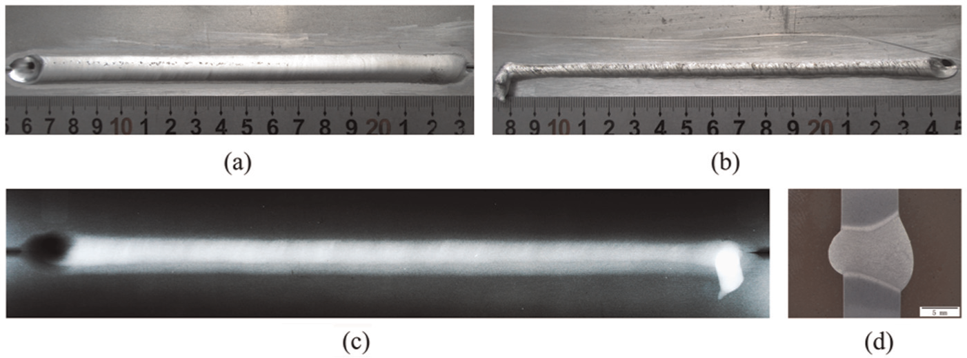
The appearances of the horizontal weld with soft plasma arc: (a) front side, (b) backside, (c) X-ray inspection image and (d) cross section.
The tensile test of the horizontal weld using the soft plasma arc was carried out. The tensile samples were shaved to remove the root and crown reinforcements. The average ultimate strengths (three samples) of the base metal and the horizontal weld were 466.1 and 314.4 MPa, respectively. The average ultimate strength of the horizontal weld was 67.5% of the base metals. This strength was basically equal to that in vertical-up position. 16 The fracture locations of the horizontal weld were in the upper part of the weld zone near the fusion boundary. The above results indicated that the soft plasma arc was effective.
Characteristic of the soft plasma arc
At present, researches on the soft plasma arc are very few and the characteristic of the soft plasma arc is not clear. The characteristic of the soft plasma arc was studied for understanding its nature.
The arc shape of the ordinary plasma arc and the soft plasma arc in DCEN duration is shown in Figure 6. The ordinary plasma arc was stiffer than the soft plasma arc. The compression degree of the soft plasma arc became lower. The arc column width of the soft plasma arc was bigger than that of the ordinary plasma arc as shown in Figure 7(a). The arc column width became larger with the increase in the welding current.
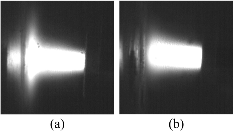
The arc shape of (a) the ordinary plasma arc and (b) the soft plasma arc.
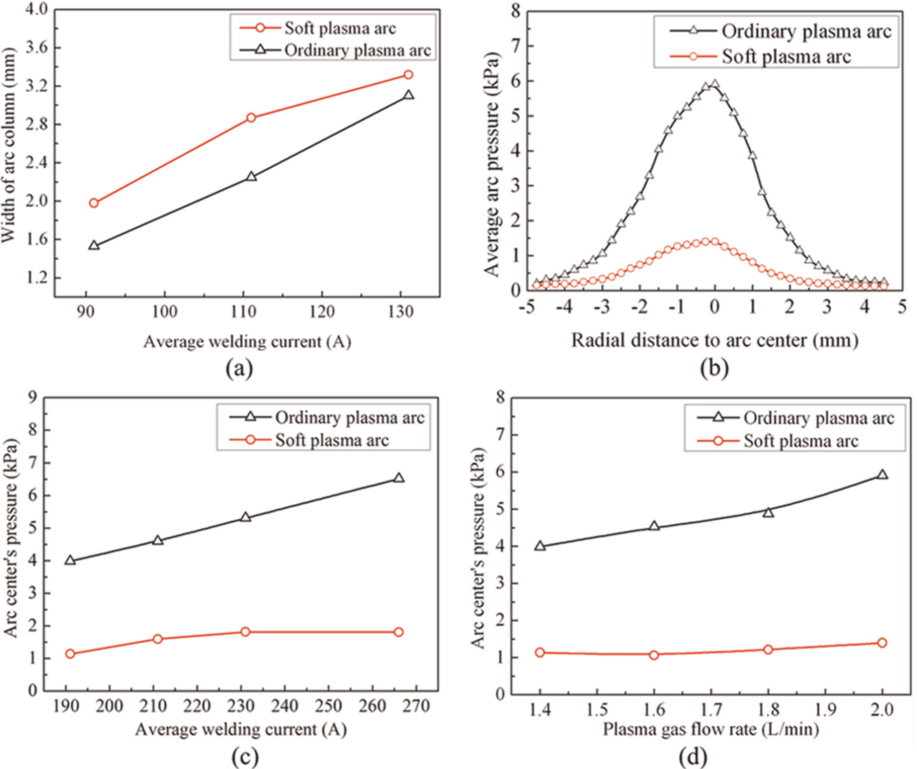
The width of arc column and the arc pressure: (a) the width of arc column, (b) arc pressure distribution, (c) arc pressure versus welding current and (d) arc pressure versus plasma gas flow rate.
The arc pressure is important because it is responsible for weld pool geometry. 24 The arc pressure waveform fluctuated regularly with the change in polarity. The frequency of arc pressure was equal to the welding currents (42 Hz). For comparison, the average arc pressure was calculated.
The average arc pressure distribution with the ordinary plasma arc and the soft plasma arc in radial direction is shown in Figure 7(b). The distribution of arc pressure was axial symmetry. The arc pressure of the soft plasma arc decreased drastically and the arc centre’s pressure was down to 1.4 from 5.9 kPa. The gradient of the arc pressure also decreased greatly.
The arc centre’s pressure varied with welding current and plasma gas flow rate as shown in Figure 7(c) and (d). With the increase in welding current or plasma gas flow rate, the arc centre’s pressure of the soft plasma arc changed a little. On the contrary, the ordinary plasma arc’s pressure increased evidently. The value of the ordinary plasma arc’s pressure was approximately 4 times that of the soft plasma arc.
The relationship between the arc pressure and welding current with soft plasma arc indicated that the electromagnetic compression became weak. The pressure of the soft plasma arc was kept approximately constant at different plasma gas flow rates. This indicated that the velocity of the plasma gas decreased by the special nozzle with three orifices.
The pressure of the soft plasma arc was not sensitive to the change in welding current or plasma gas flow rate and this would be beneficial to the stability of keyhole.
Weld pool’s shape
The shape of the weld pool was changed when the soft plasma arc was used as shown in Figure 8. The cone shape of the weld pool with soft plasma arc was elongated in welding direction, that is, the width of the weld pool was smaller than its length. Moreover, the gradient of the internal wall of the weld pool became smaller compared with that using the ordinary plasma arc. In addition, the keyhole with soft plasma arc was circular and symmetric and its diameter was smaller than that using the ordinary plasma arc.
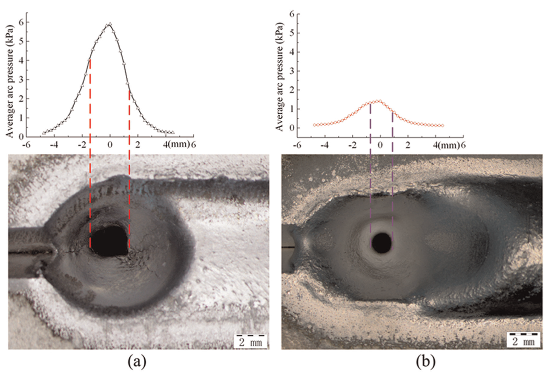
The shape of weld pool: (a) with the ordinary plasma arc and (b) with the soft plasma arc.
The soft plasma arc’s pressure contributed to the change in the weld pool’s shape. From Figure 8, we can see that the arc pressure in the left side of the keyhole was larger than that in the right side. The larger arc pressure in the left side was beneficial to the keyhole’s expansion and the lower arc pressure in the right side promoted the closure of the keyhole. The gradient of the arc pressure had a relationship with the slope of weld pool’s internal wall.
Fluid flow in weld backside
The fluid flow of the weld pool in the backside using the ordinary plasma arc is shown in Figure 9. The evolution of the fluid flow in weld backside could be seen clearly from the schematic diagrams. At the beginning, the molten metal was pulled to the lower side by the gravity and accumulated gradually. When the gap between the upper part and the lower part became small enough, in the rear of the keyhole, the gap could be filled by the molten metal from the upper part. At this moment, the size of the keyhole was the smallest. As the keyhole closure process continued, the expansion process of the keyhole was conducted simultaneously.
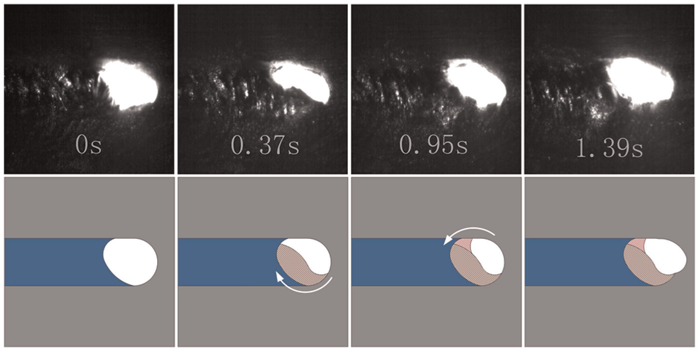
The evolution of the fluid flow in weld backside.
Discussion
Understanding the conditions that make the weld pool stable is the fundament of discussion. Many researchers have studied the stability of the weld pool in vertical-up position.25–29 The conditions can be summarized as follows. One condition is that there should be enough molten metal to form the weld pool determined by its fluid flow and temperature field. Another condition is that the weld pool should be maintained steadily determined by its force balance. The following discussion is carried out under the two conditions.
Bridging molten metal
Proper fluid flow and enough molten metal are needed to form the weld pool and this is easy in vertical-up position. The gravity pulls the liquid in the direction in which it is supposed to flow and the molten fluid in two sides meets in the rear of the weld pool. The weld pool is formed by bridging the molten fluid in two sides. The style of the fluid flow in vertical-up position makes the bridging be realized easily.
The fluid flow in horizontal position is different from that in vertical-up position. From Figure 9, we can see that the fluid flow in both the sides is not symmetric and large amount of molten metal gathers in the lower part. The effect of capillary contributes to the filling of the gap. So the wetting and spreading of molten metal in the backside is important to the forming of the keyhole.
The influence of joint configurations on the forming of the keyhole can be explained. The change in joint configurations makes the effective thickness of the welding plates be thinner. The temperature in the backside will be higher and the amount of the molten metal will be more. This promotes the wetting and spreading of the molten metal in the backside. The molten metal in the upper part and the lower part can be bridged and the keyhole is established simultaneously.
The forming mechanism of the undercut can be explained. The location of the undercut is in the upper part of keyhole where the molten metal in the two sides meets. This location is lack of molten metal due to the asymmetric flow and then the undercut will be formed. With the increase in the welding current, as shown in Figures 2 and 3, the undercut is eliminated because the flowability of the molten metal in the backside becomes well. So the undercut is caused by bad fluid flow in the backside.
Force balance
The second condition which can maintain a stable weld pool is the force balance of the weld pool. The forces acting on the weld pool in 2G position are shown in Figure 10.
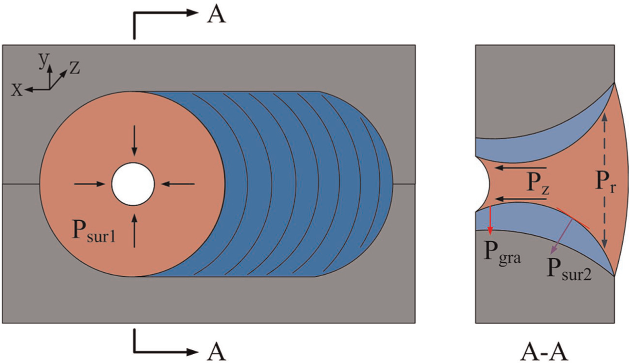
A schematic diagram of the forces acting on the weld pool in 2G position.
In the left half part of the keyhole, the surface tension should be smaller than the arc force for the expansion process. Contrarily, in the right half part, the surface tension should be little bigger than the arc force for the closure process. This can be seen in Figure 8. The main problem in horizontal welding is that the keyhole cannot close well. The condition of the closure of the keyhole in backside is described in equation (1)

Because

So
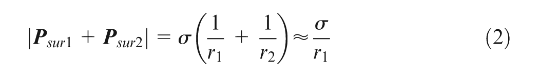
where
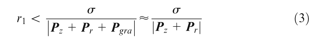
where

From equation (3), we can see that if we reduce the arc pressure we will obtain a bigger curvature radius. This means that even the diameter of the keyhole is a little bigger in welding process and the weld pool is still stable. This is the theory foundation of using the soft plasma arc.
From Figure 7(c) and (d), we can see that the minimum arc pressures of arc centre with the ordinary plasma arc and soft plasma arc are 4 and 1 kPa, respectively. The value of
The values of r1.
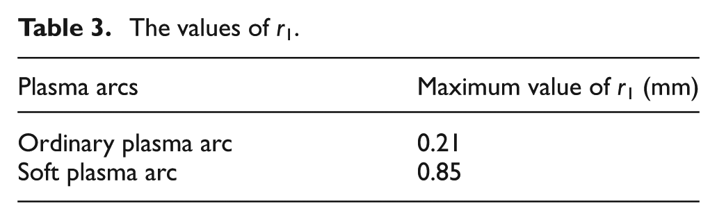
If the keyhole’s shape can approximate circular shape, the radius of the keyhole is equal to the curvature radius r1. So the maximum diameters of the keyhole using the ordinary plasma arc and soft plasma arc are 0.42 and 1.7 mm, respectively. The maximum diameter of the keyhole using the soft plasma arc is bigger than that using the ordinary plasma arc. So the keyhole is more stable in welding process with the soft plasma arc. The measured diameter of the keyhole in Figure 8(b) is 1.5 mm which agrees with the calculated result. So using the soft plasma arc can improve the stability of the keyhole.
Moreover, using the soft plasma arc is beneficial to the weld formation in the front side. The arc pressure in the rear of the weld pool is lower as shown in Figure 8. The wetting and spreading of the molten metal in the front side becomes easy. So the sag in the front side is eliminated and then the improved horizontal weld is obtained.
Conclusion
The soft plasma arc was used in horizontal welding of aluminium alloys. The experimental results indicated that the method was effective. The following conclusions were derived:
The weldable thickness was less than 8 mm and the stable weld pool was difficult to form only controlled by welding parameters with the ordinary plasma arc. When the joint configuration was changed to single ‘V’ groove, the weld pool was formed, but the horizontal weld formation was bad. Higher welding current was beneficial to eliminate the undercut in backside.
Horizontal welding of aluminium alloy plates with 8 mm thickness was realized successfully by using the soft plasma arc. The joint was free of undercut and porosity defects and had excellent mechanical properties.
The arc pressure of the soft plasma arc was smaller than that of the ordinary plasma arc. The soft plasma arc’s pressure was not sensitive to the change in welding parameters. The weld pool’s shape was elongated in welding direction.
The fluid flow in weld backside was not symmetric and large amount of molten metal gathered in the lower part. The wetting and spreading of molten metal in the backside was important for the forming of the weld pool. The undercut was caused by the bad fluid flow in the backside.
The force balance of weld pool was needed except the proper fluid flow. The keyhole was more stable with soft plasma arc because the maximum diameter of the keyhole was bigger than that with the ordinary plasma arc.
Footnotes
Declaration of conflicting interests
The authors declare that there is no conflict of interest.
Funding
This research received no specific grant from any funding agency in the public, commercial or not-for-profit sectors.