
Abstract
This article reveals the influence of laser welding process parameter, welding speed, on the mechanical and metallurgical properties of 3.5 kW CO2 laser machine welded joints of 70/30 Cu-Ni alloys. Laser welded joints were fabricated using different welding speeds of 1.0, 1.5, 2.0, and 2.5 m/min. The mechanical properties (hardness, tensile strength, and percentage elongation) of the welded joints were evaluated and correlated with the fusion zone microstructure. Optical microscopy and scanning electron microscopy were used to evaluate the metallurgical characteristics of the welded joints. The joints fabricated using a welding speed of 1.5 m/min exhibited fine, equiaxed, and uniformly distributed grains at fusion zone and resulted in superior mechanical properties than other joints.
Introduction
Cupronickel alloys have been widely used in naval and marine construction applications such as ship piping, boat hulls, conduits, pump impellers, pump bodies and components, sea water condensers, valve bodies, pipe fittings, heat exchanger tubes, boiler parts, and other structures engineered for marine use because of their resistance to avoid marine corrosion and anti-fouling properties. 1 Previous studies on gas tungsten arc welding (GTAW) and gas metal arc welding (GMAW) have indicated porosity, excessive material loss, and solidification cracking as the most commonly encountered problems in the laser welding of cupronickel alloys. 2 Although GTAW and pulsed gas metal arc welding (GMAW-p) produce clean and hydrogen-free joints, they are relatively slow welding processes. Laser welding could be developed to replace most of the GTAW and GMAW-p applications.
Industrial lasers are used in wide range for welding, cutting, drilling, and surface treatment of engineering materials. 3 Recent studies were carried out on materials such as aluminum alloys, magnesium alloys, titanium alloys, and stainless steel for the evaluation of mechanical and metallurgical properties of laser welded joints. 4 –9
It has been reported that the effects of CO2 laser beam welding (LBW) process parameters (2.5 kW laser power, 5.5 m/min welding speed, and −1.5 mm focal position) showed an improvement in mechanical properties of AZ31B magnesium alloy due to the formation of very fine grains in weld region and uniformly distributed finer precipitates. 4
A pulsed Nd:YAG laser to weld 4-mm-thick V-Cr-Ti sheets achieved good welding under an optimum combination of laser parameters including focal length of lens, 1.6 kW pulse power, welding speed (0.15–0.6 m/min), and argon shielding gas. 5
Pulse energy, duration, and peak power play major role in improving mechanical properties during the welding of 3-mm-thick Ti-6Al-4V by using Nd:YAG pulsed laser. 6 Ti-6Al-4V (5.1-mm-thick) sheets were welded efficiently by laser welding of 4 kW power at various welding speeds (0.7–1.5 m/min) using a spot diameter of 0.45 mm, focal length of 200 mm, and flow rate of argon of 23.6 L/min. 7
It has been reported that the use of 4 kW CO2 laser beam with welding speed of 6 m/min has resulted in full penetration of 2-mm-thick aluminum alloy welded joint, while 5 kW and 5 m/min has resulted in full penetration of 3-mm-thick aluminum alloy welded joint. 8 There was no thorough report so far on the use of LBW for joining 70/30 Cu-Ni alloy welds. In this experiment, an attempt has been made to study the effect of 3.5 kW CO2 laser welding with different welding speeds (1.0, 1.5, 2.0, and 2.5 m/min) to find the mechanical properties (hardness and tensile strength) and microstructure of 70/30 Cu-Ni welds.
Experimental details
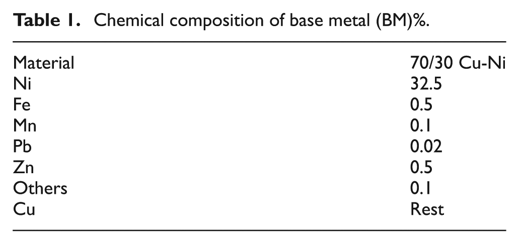
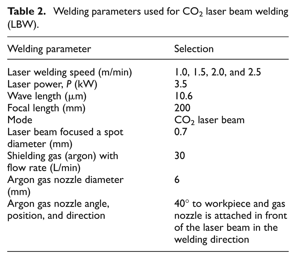
The investigations were carried out on a 5-mm-thick plate of 70/30 cupronickel alloy. The chemical composition of base metal (BM) (70/30 Cu-Ni alloy) is given in Table 1. Details of the LBW parameters are shown in Table 2.
Chemical composition of base metal (BM)%.
Welding parameters used for CO2 laser beam welding (LBW).
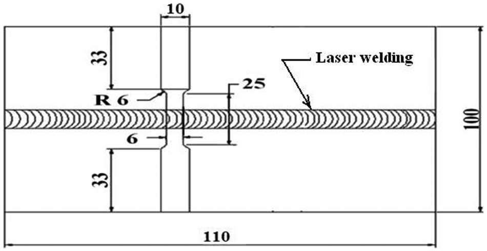
Square butt joint specimens were made with machined surfaces and were firmly held using fixture to prevent distortion. A schematic diagram of the laser welding machine, dimensions of laser butt weld joints (no air gap between the plates) and Transverse tensile test specimens (the weld bead perpendicular to the plate rolling direction) are shown in Figures 1–3 respectively. The samples of welds from the fusion zone (FZ) region were polished with emery papers and disk cloth to remove fine scratches. Polished surfaces were etched with glacial acetic acid and nitric acid (1:1). Microstructures and tensile fracture structures were observed using both optical microscope and scanning electron microscope (SEM). Vickers microhardness testing was carried out across the weld regions of the sample with 2 kgf (19.62 N) load applied across the weld cross section for 20 s dwell time. Hardness survey along the transverse direction of the weld was conducted with hardness measurements at regular intervals of 2 mm from the centerline of the weld to either side. The average of the three readings is taken as the required hardness value.
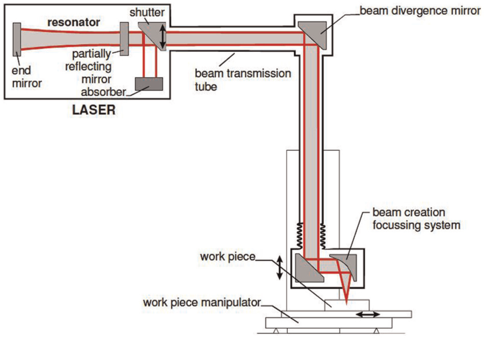
Schematic diagram of laser welding machine.
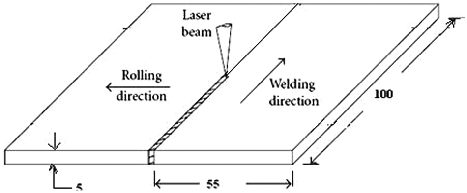
Dimensions of laser butt weld joints.
Transverse tensile test specimens.
Transverse tensile specimens were prepared from the weldments as per the ASTM standard E8 (Figure 4) and testing is carried out using computerized universal testing machine (UTM) of capacity 100 kN. Three specimens were tested in each condition and the average value is reported. The fractography of the fractured tensile specimens is performed using SEM. SEM micrographs are useful in identifying the various phases at higher magnifications that are not detected through optical micrography.
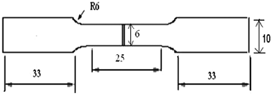
Tensile test specimen as per ASTM E8 cut from weld specimen.
Results and discussion
The face side and root side of the weld bead of 70/30 Cu-Ni alloy laser welds are shown in Figure 5(a) and (b), respectively.
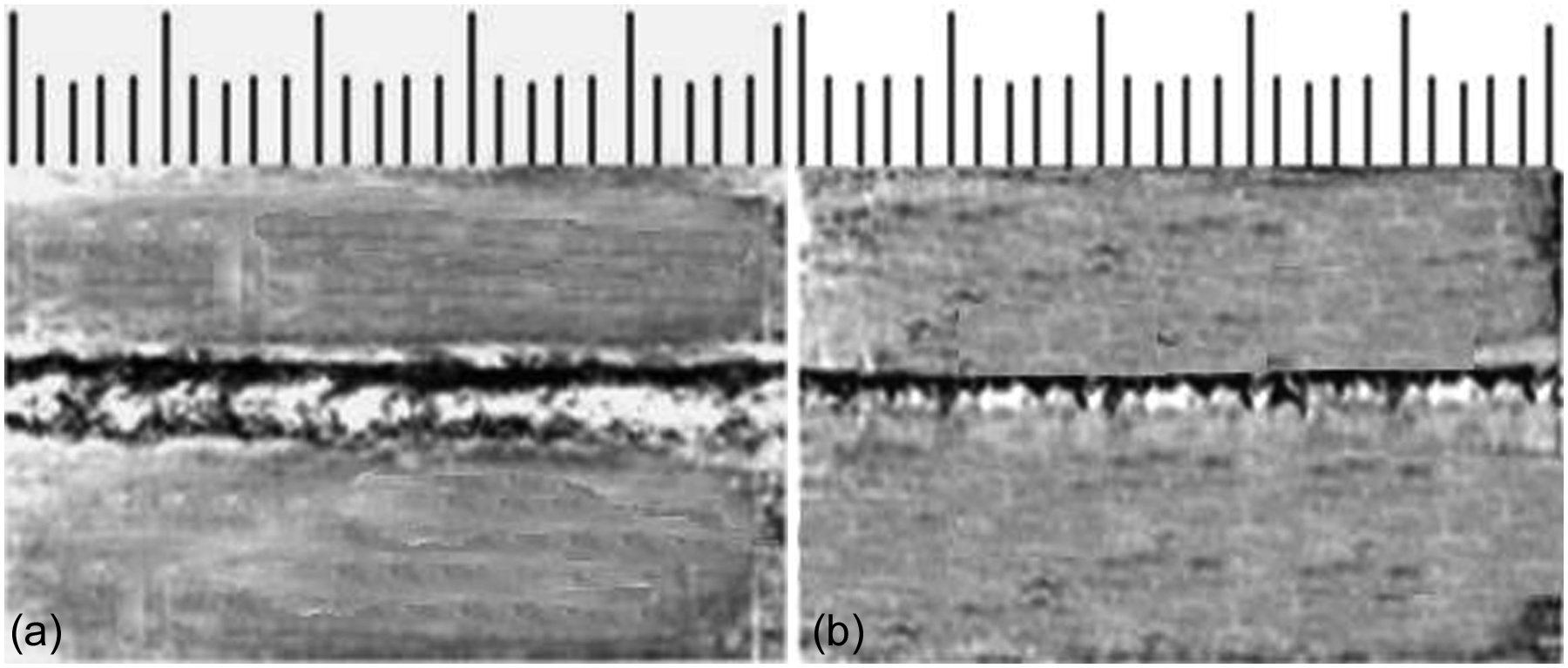
70/30 Cu-Ni alloy laser welds: (a) welding face side and (b) root side.
For comparison of higher version to lower version welding techniques, an experiment was done on 70/30 Cu-Ni alloy of 5-mm-thick plate with 60° single “V” butt joints which were successfully welded using GTAW with considered welding parameters such as arc voltage 18 V, welding current 105 A, welding speed 2.5 mm/s, filler wire ERCuNi (70/30), and shielding gas argon.
Figure 6(a) and (b) shows the optical microstructure of LBW and GTAW welds, respectively. LBW welds show small heat-affected zone (HAZ) compared to GTAW welds.
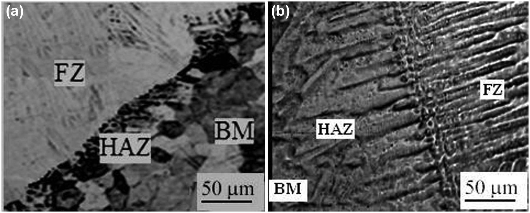
Optical micrographs: (a) LBW and (b) GTAW of 70/30 Cu-Ni alloy welds of FZ and HAZ interface.
Microstructure
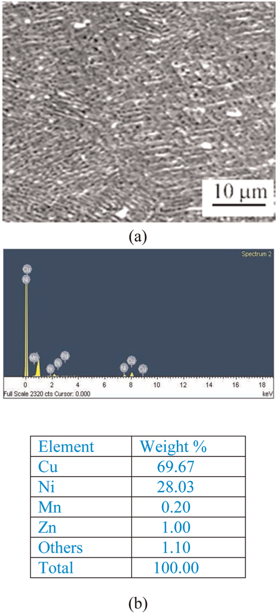
Figures 7 and 8 show optical microstructure and SEM-energy dispersive spectroscopy (EDS) analysis of BM, respectively. BM shows coarse grains throughout the structure (Figure 7). SEM-EDS values of BM (Figure 8(b)) were near to the BM values (Table 1).
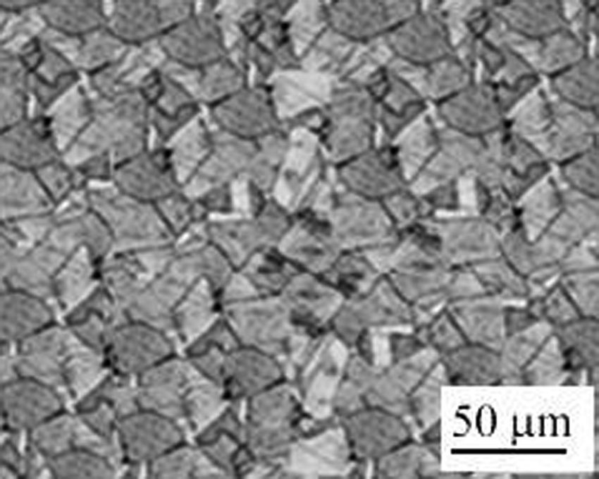
Optical microstructures of BM of 70/30 Cu-Ni alloy.
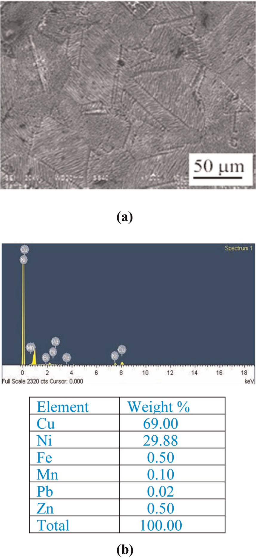
BM of 70/30 Cu-Ni alloy (a) SEM Microstructure (b) EDS results.
FZ with welding speeds (1.0, 1.5, 2.0, and 2.5 m/min) are shown in Figure 9(a)–(d).
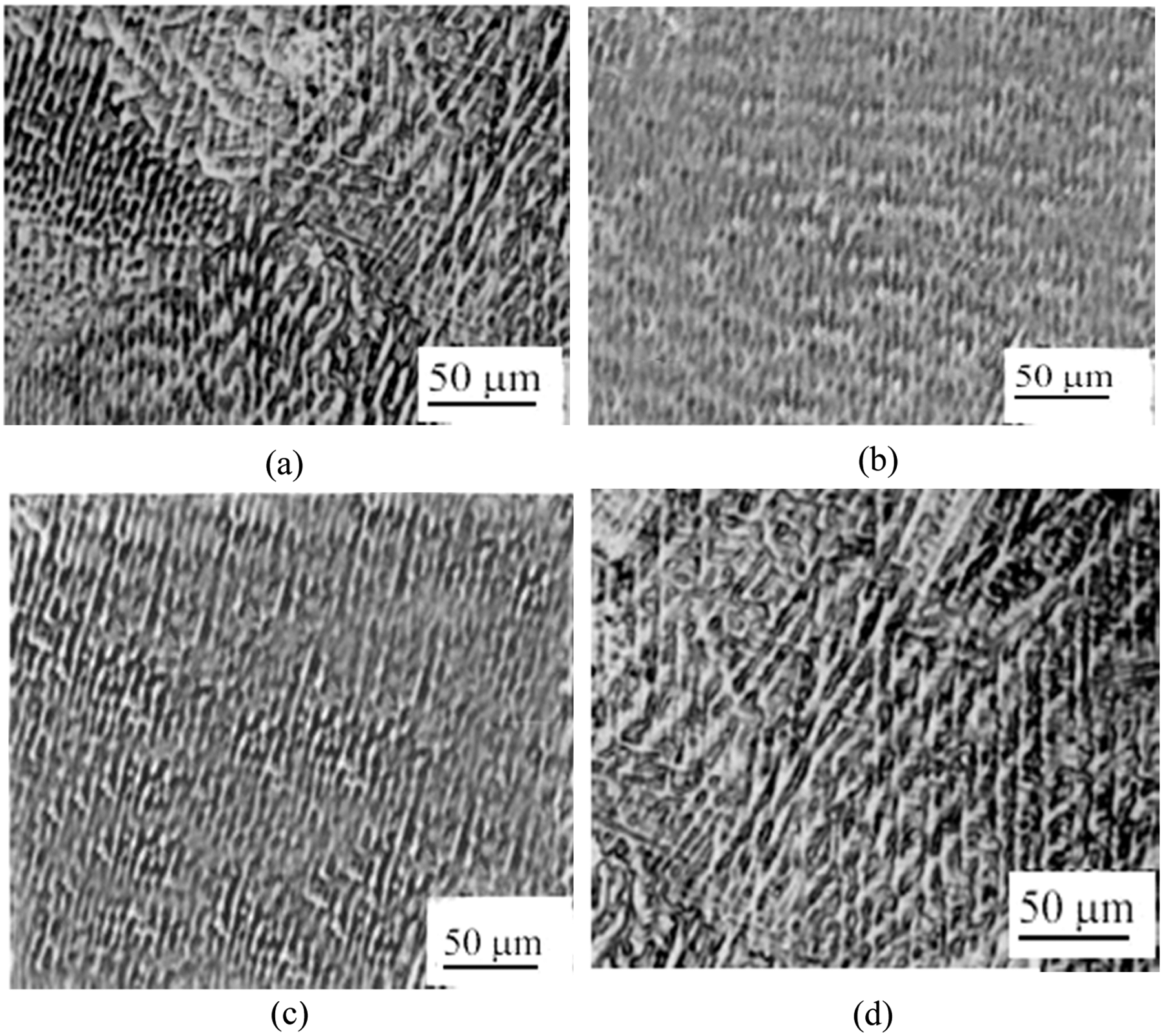
Optical micrographs, LBW, of 70/30 Cu-Ni alloy welds of welding speeds: (a) 1.0, (b) 1.5, (c) 2.0, and (d) 2.5 m/min in FZ.
Of all the laser welding speeds, 1.5 m/min welding speed exhibited fine and equiaxed grains (Figure 9(b)). The same was revealed in SEM microstructures and is shown in Figure 10(a).
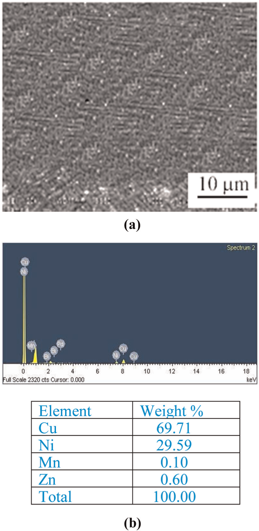
Characteristics of LBW of 70/30 Cu-Ni alloy welds at 1.5 m/min (a) at FZ (SEM-1000×) and (b) EDS result.
SEM images showed fine and equiaxed grains of laser welds at 1.5 m/min and coarse grains at 2.5 m/min compared to FZ of other welds as shown in Figures 10(a) and 11(a), respectively. The formation of fine and equiaxed grains and uniformly distributed, very fine strengthening precipitates in the weld region are the reasons for superior tensile properties of laser welds at 1.5 m/min.
Characteristics of LBW of 70/30 Cu-Ni alloy welds at 2.5 m/min (a) at FZ (SEM-1000×) and (b) EDS result.
The SEM-EDS results of FZ with a welding speed of 1.5 m/min as shown in Figure 10(b) confirm that the matrix composition in the FZ is mostly concentrated by high value in wt% of Cu and Ni and less value in wt% of Zn than the other laser welds.
Of the four welding speeds (1.0, 1.5, 2.0, and 2.5 m/min), laser welds fabricated with 2.5 m/min welding speed exhibited lower tensile strength value.
The SEM-EDS results of FZ with a welding speed of 2.5 m/min as shown in Figure 11(b) confirm that the matrix composition in the FZ is mostly concentrated by low value in wt% of Cu and Ni and more value in wt% of Zn in the matrix (due to evaporation caused by high peak temperature) than the laser welds at 1.5 m/min. This may be one of the reasons for the reduction in tensile properties of the laser welds at 2.5 m/min compared to 1.5 m/min. Figure 12(a)–(d) shows the difference in width and depth of penetration of transverse sections of laser welds at all speeds (1.0, 1.5, 2.0, and 2.5 m/min).
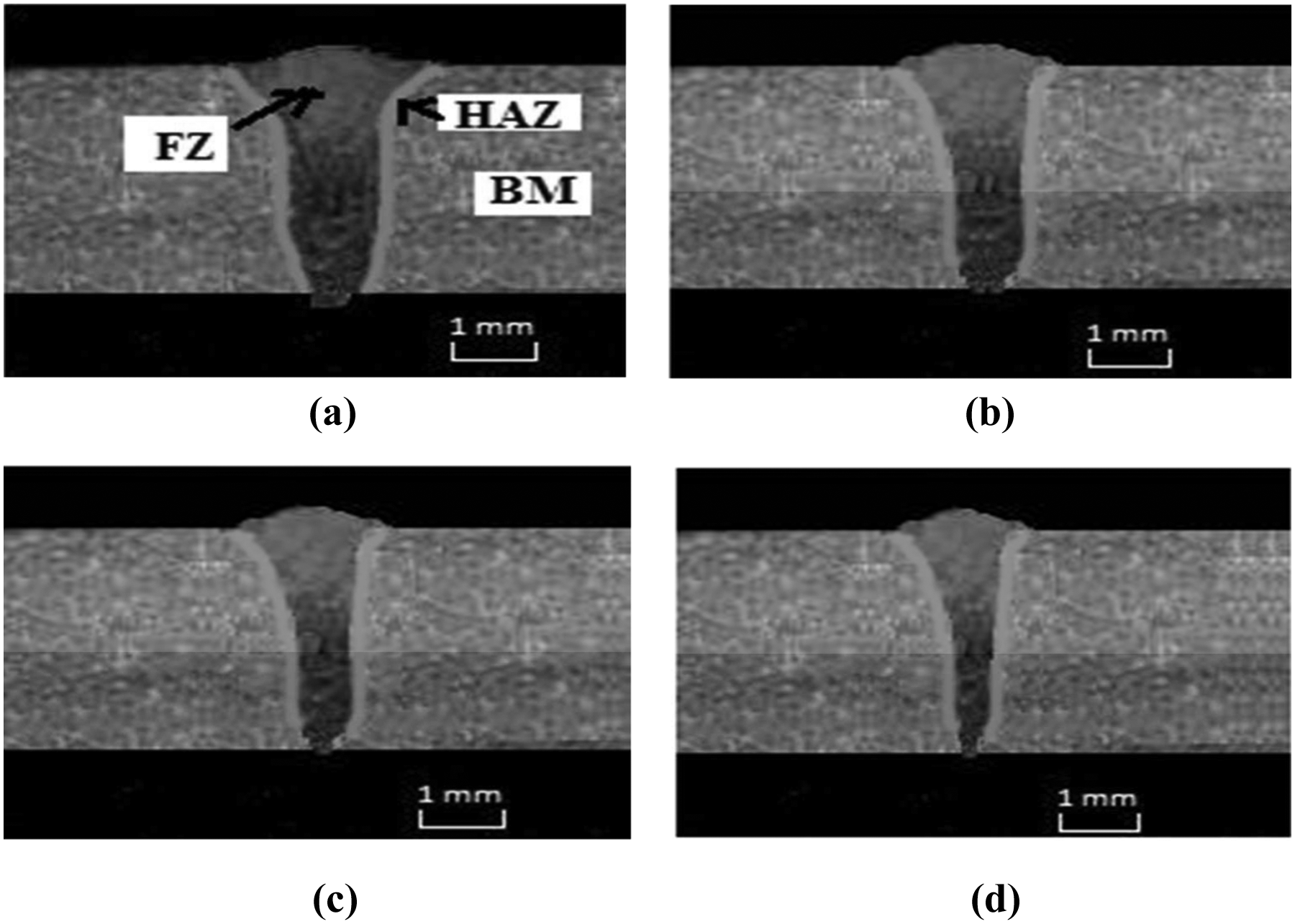
Optical macrograph of transverse sections obtained at various welding speeds: (a) 1.0, (b) 1.5, (c) 2.0, and (d) 2.5 m/min in FZ.
Figure 12(b) shows that laser welds at welding speed 1.5 m/min exhibited good depth of penetration, bead width, and less HAZ compared to all other laser welds at different welding speeds. This is one of the reasons for superior mechanical properties than in other welding speeds.
Figure 12(a) shows that laser welds at welding speed 1.0 m/min exhibited further increase in depth of penetration, bead width, and area of penetration because of the increase in the exposure time of laser energy on the workpiece which resulted in inferior mechanical properties compared to laser welds at welding speed 1.5 m/min.
Figure 12(d) shows that laser welds at welding speed 2.5 m/min exhibited further decrease in depth of penetration, bead width, and area of penetration because of the decrease in the exposure time of laser energy on the workpiece which resulted in inferior mechanical properties compared to laser welds at welding speed 1.5 m/min.
Microhardness
The microhardness profiles under different laser welding speeds of 1.0, 1.5, 2.0, and 2.5 m/min are taken across different locations on the transverse direction of FZ in order to evaluate the matrix interparticles’ hardness, that is, possible hardening or softening effects induced by LBW in the Cu-Ni matrix, and the microhardness profiles are shown in Figure 13. It can be seen that local softening of the material occurs in the weld because of the dissolution of precipitates, and the welding thermal cycle does not promote nucleation and growth of all the precipitates. This result could be attributed to the occurrence of lower hardness in HAZ than in BM.
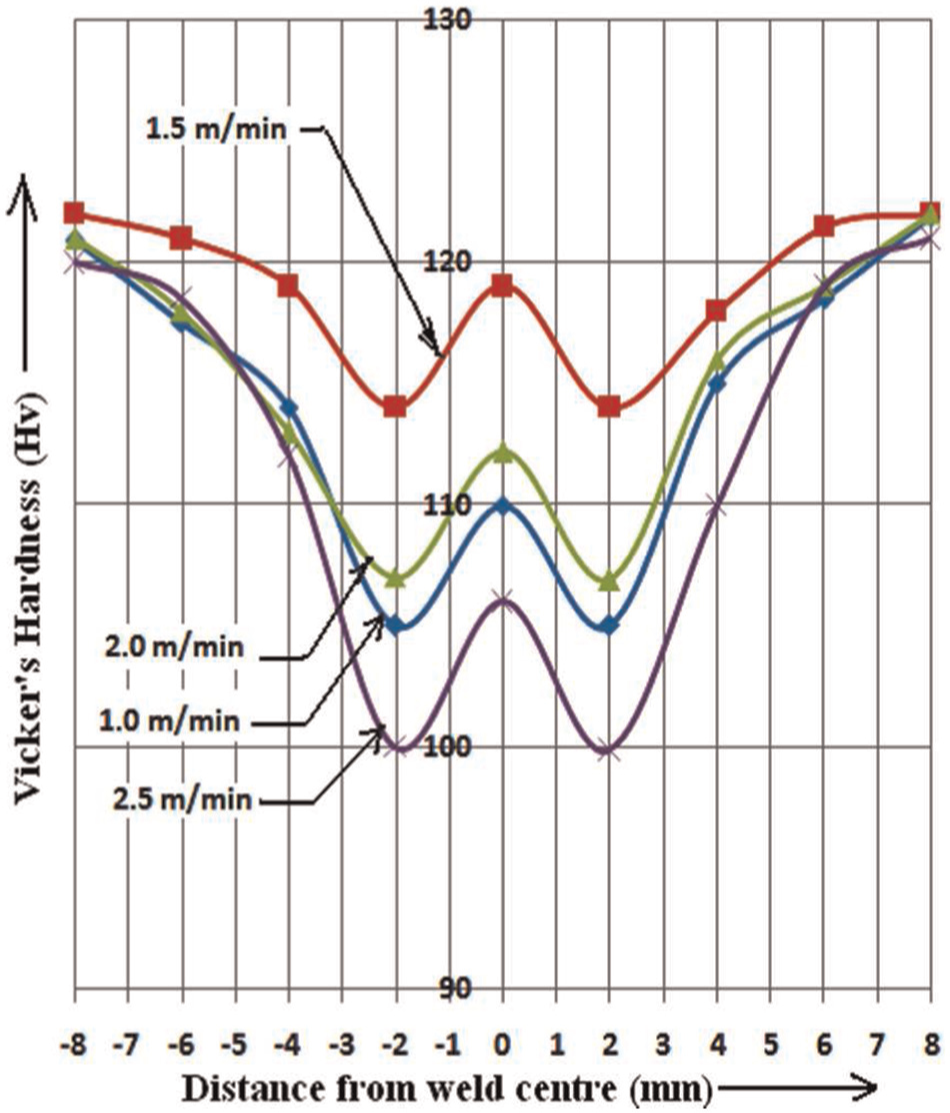
Microhardness profiles on top surface of the weld with different laser welding speeds (1.0, 1.5, 2.0, and 2.5 m/min) of 70/30 Cu-Ni alloy laser butt welds.
Hardness profile is high in FZ because this zone has fine grains compared to HAZ, but lower than the BM. The hardness profile is low in HAZ portion because of the presence of deformed grains.
Compared to all laser welding speeds, the highest hardness value (115.0 Hv) was observed in the FZ at 1.5 m/min welding speed because of fine grains, and the lowest hardness value was observed at 2.5 m/min welding speed (106.0 Hv) because of coarse grains.
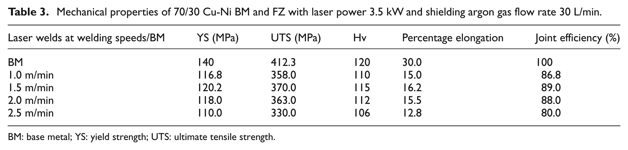
Welding speed 1.5 m/min exhibits higher hardness (115.0 Hv) in the FZ due to high wt% of Cu and Ni particles and fine grains throughout the weld region (Figure 11), and this is one of the reasons for the superior microhardness of FZ. The microhardness values of BM and FZ made with all welding speeds (1.0, 1.5, 2.0, and 2.5 m/min) are shown in Table 3.
Mechanical properties of 70/30 Cu-Ni BM and FZ with laser power 3.5 kW and shielding argon gas flow rate 30 L/min.
BM: base metal; YS: yield strength; UTS: ultimate tensile strength.
Tensile strength
This study evaluated the mechanical properties, namely, yield strength, tensile strength, percentage elongation, and the joint efficiency, of the laser welded 70/30 Cu-Ni alloy joints. In each condition, three specimens were tested and their average value is presented in Table 3.
Table 3 shows that cupronickel alloys absorb laser more efficiently as the wavelength of CO2 laser beam is 10.6 µm, power is 3.5 kW, laser beam focused a spot diameter 0.7 mm, focal length is 200 mm, shielding gas flow rate is 30 L/min, and welding speeds provided better joining of cupronickel alloys. Therefore, the CO2 laser beam seems to be more attractive for the welding of cupronickel alloys.
Figure 14 shows load versus elongation graphs of BM and LBW welds. The mechanical properties (yield strength, ultimate tensile strength, and percentage elongation) of BM and FZ made with welding speeds (1.0, 1.5, 2.0, and 2.5 m/min) are shown in Table 3.
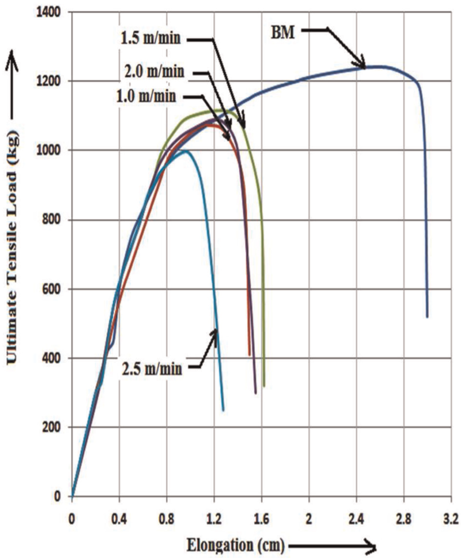
Effect of LBW on tensile strength of 70/30 Cu-Ni alloy welds at different welding speeds (1.0, 1.5, 2.0, and 2.5 m/min).
Joint efficiency is the ratio of strength of BM to laser welds. The joint efficiency of laser welds at welding speed of 1.5 m/min exhibited higher percentage (89%) compared to all other laser welds.
Welding speed of 1.5 m/min shows higher yield strength, ultimate tensile strength, and percentage elongation than all other welding speeds. This may be due to the formation of fine grains in the FZ as shown in Figure 9(b).
BM shows better strength than all welds as shown in Figure 14 and Table 3. Transverse locations of the tensile test specimen of BM (three samples) are shown in Figure 15(a), and the locations of failure of tensile specimens of LBW joints (1.0, 1.5, 2.0, and 2.5 m/min) are observed at the interface of FZ and HAZ as shown in Figure 15(b), which exhibits lower hardness (Figure 13). Detailed failure locations of LBW joint during tensile test are shown in the top view and cross-sectional view in Figure 15(c).
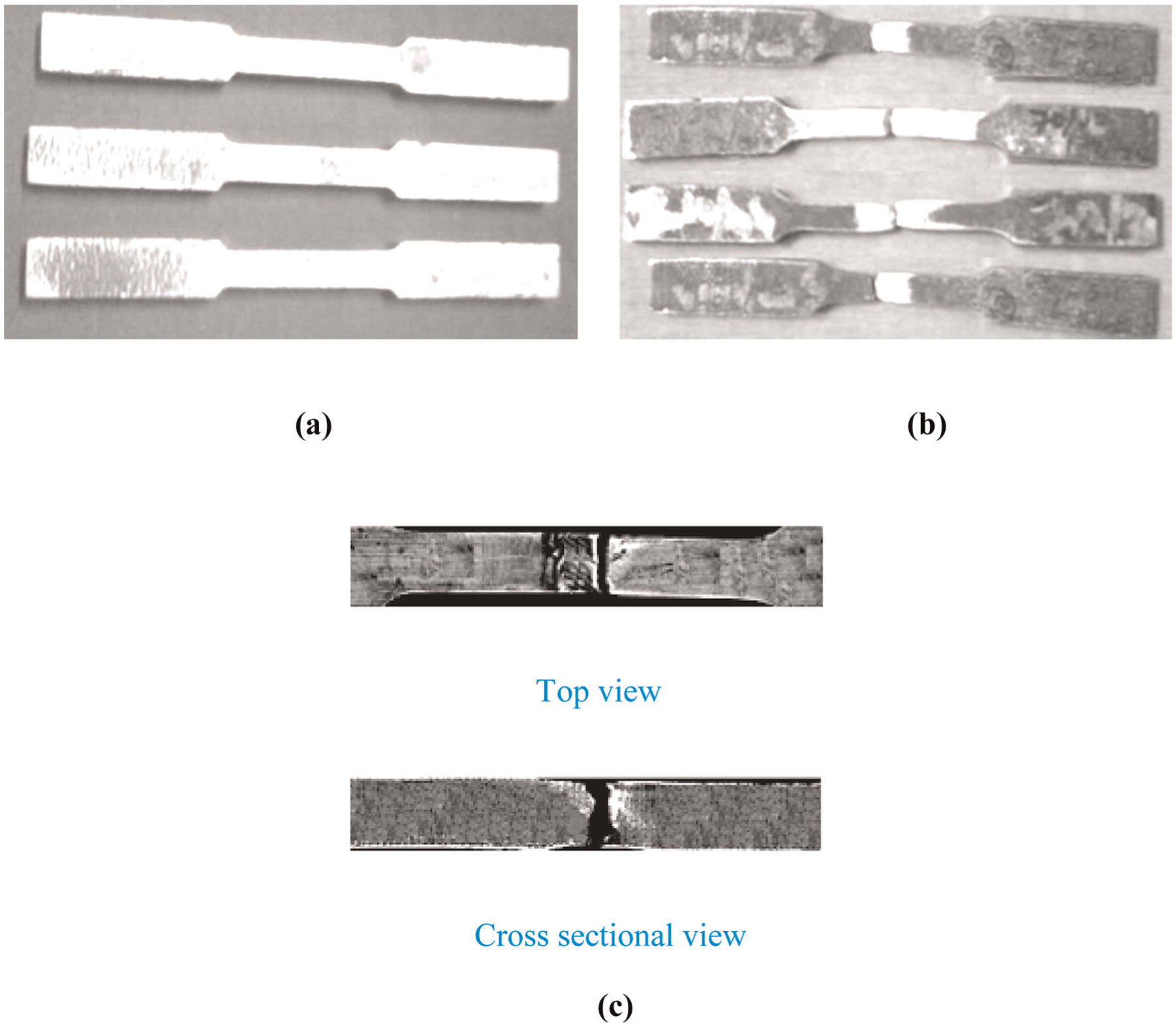
(a) ASTM E8 tensile specimens of BM, (b) LBW tensile test fractures, and (c) detailed failure locations of LBW joint during tensile test.
Tensile fracture surface of both BM and 1.5 m/min laser welds was observed with SEM. Tensile fracture of BM through SEM fractography revealed voids in wide range of sizes and shallow dimples as shown in Figure 16(a), whereas 1.5 m/min laser welds exhibited voids with various sizes and deep dimples as shown in Figure 16(b). Thus, BM exhibited less ductile nature of fracture and resulted in superior mechanical properties.
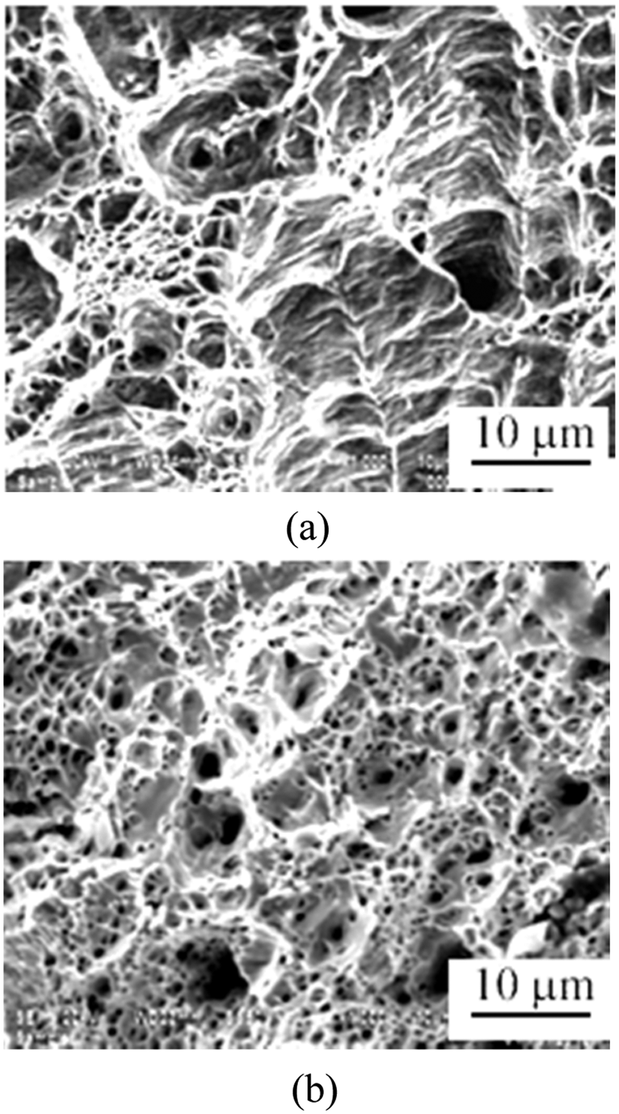
70/30 Cu-Ni SEM, 10 µm fractured surface: (a) BM and (b) welding speed (1.5 m/min).
Conclusion
The following conclusions are drawn:
70/30 Cu-Ni alloy welds were successfully welded by 3.5 kW CO2 LBW.
The formation of uniformly distributed, equiaxed fine grains and very fine strengthening precipitates in the weld region resulted in superior mechanical properties (hardness and tensile strength) of laser welds at 1.5 m/min compared to laser welds at other welding speeds.
Of the four welding speeds (1.0, 1.5, 2.0, and 2.5 m/min), laser welds fabricated with welding speed 1.5 m/min exhibited higher yield strength (120.2 MPa), tensile strength (370 MPa), hardness (115.0 Hv), elongation (16.2%), and joint efficiency (89.7%).
Tensile fracture through SEM fractography of laser welds with 1.5 m/min revealed voids with various sizes and deep dimples which exhibited less ductile nature of fracture and thus resulted in inferior mechanical properties than BM.
Footnotes
Declaration of conflicting interests
The authors declare that there is no conflict of interest.
Funding
This research received no specific grant from any funding agency in the public, commercial, or not-for-profit sectors.