
Abstract
This article proposes a method to find the optimized manufacturing procedure of ejector using differential evolution algorithm. To obtain the optimized machining conditions, the performance of ejector was analyzed based on the computer simulation, and machining condition during manufacturing was used to design the evaluation function. Based on the computer simulation and experiments results, the evaluation function for optimization and the manufacturing constraints were induced in this article. The functionality of the proposed method was verified through experiments.
Introduction
To maintain the stability and increase the efficiency of the propulsion of vessel, a ballast tank is installed in cargo ship. Ballast system is to ensure the safe navigation and to reduce the changes of ship’s center of gravity according to loading and unloading a cargo. The ballast will remain below the water level, to counteract the effects of weight above the water level. While loading cargo, the ballast discharges tons of seawater with microbe, pathogens, mollusks, fish, and so on to empty ballast tank. This is the main cause of sea pollution. In order to prevent sea pollution, some devices have been developed and installed to the ballast system. The representative devices to sterilize microbe are to use ultraviolet (UV) ray and ozone. The device using ozone needs the ejector to inject the ozone to main pipe connected with ballast tank.
Ejector is designed with considering the entrainment performance, and there is lots of design parameters related with the performance of the ejector. Some of these parameters affect the amount of suction of the ejector, but some of the parameters are trivial factor in the ejector performance. However, these trivial factor parameters sometimes affect productivity of ejector. Therefore, in this article, we proposed the decision method to determine the design parameters in terms of performance and productivity of ejector based on the experimental data.
The experimental studies of the effect of primary nozzle throat size and ejector geometry on system performance were conducted. 1 Theoretical study of ejector can be classified into two categories: constant-area mixing methods and constant-pressure mixing methods, both of which were first proposed by Keenan et al. 2 The latter are believed to give superior performance and are therefore more widely used. Mikhail 3 assumed different velocity profiles at each stage of the mixing process in a constant-area tube to solve the linearized integral momentum equation.
Hedges and Hill 4 developed a finite-difference scheme to model the flow process, which was the first venture into what is recognized today as computational fluid dynamics (CFD). The mixing tube length has been paid close attention due to its significant effect on the mixing of the primary and secondary flows. In the experimental study of Dirix and Van der Wiele, 5 the mixing tube length seems to have obvious effect. The effects of ejector geometries were investigated numerically. The results of CFD were validated with experimental data provided by others. 6 Especially, the CFD studies of Kandakure et al. 7 and Balamurugan et al. 8 indicate that the entrainment rate is the highest when the ejector ratio is equal to 0.
As many earlier researches, they have studied about the performance factor of ejector, but the feasibility of production of parts for the ejector is not considered. Therefore, in this article, we have analyzed the productivity for the mass production of ejector and investigated the relationship between productivity and performance of ejector. First of all, the performance of the ejector produced at “N” corporation in Korea is analyzed through experiments and CFD method, and we induced the function to represent the performance in terms of some parameters. To investigate the productivity, we received the help of the empirical skill of machining engineer who produces the ejector and designed the function for manufacturing time and the machining constraint function for manufacturing of ejector. Based on the induced function, the optimization algorithm is proposed in this article, and the performance of optimized value is evaluated through experiments.
This article is divided into five sections. Section “Structure and design parameters of ejector” explains structure and design parameters of ejector. Section “Analysis of production” presents the procedure of production. Optimizing method is proposed in section “Optimized result and evaluation,” and the experiments and analysis of the proposed method are represented in section “Optimized result and evaluation.” Finally, section “Conclusion” presents the conclusions.
Structure and design parameters of ejector
The external appearance of ejector is different according to the manufactures and purpose, but the operating principle is the same. A fluid at high pressure is accelerated by a nozzle and then the high-speed jet entrains and compresses an inlet fluid at low pressure. The simple drawing and design parameters of ejector produced in “N” corporation in Korea are presented in Figure 1.
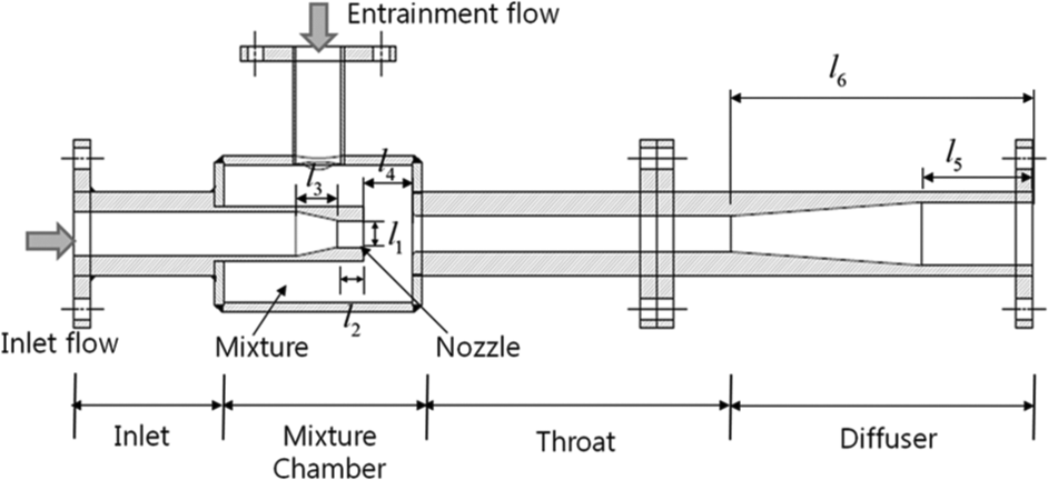
Simple drawing for ejector.
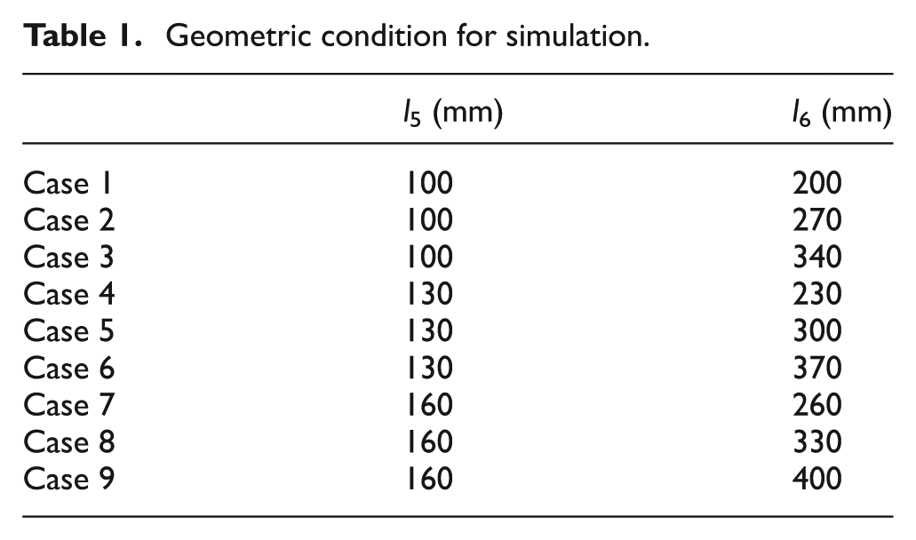
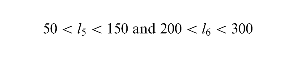
In this structure, there exits lots of design parameters and they are related with the entrainment of ejector. The representative design parameters, l1–l6, are represented in Figure 1. Most important parameters directly connected with the amount of suction belong to the mixture chamber, and others are trivial parameter in terms of the amount of suction. In Balamurugan et al. 8 and Sriveerakul et al., 9 distribution of pressure is represented for whole ejector, while entrainment is obtained experimentally. Through the experiment in Balamurugan et al. 8 and Sriveerakul et al., 9 we can infer that the parameters, l5 and l6, are not too much related with the amount of suction. In order to verify the performance of suction according to change of parameters, l5 and l6, several different cases of finite element method (FEM) simulations are carried out and compared. For the computer simulations, the commercial FEM package, ANSYS, is used as the grid generator and the CFD solver. The geometric conditions for l5 and l6 used in simulations are summarized in Table 1. Three-dimensional (3D) model for simulation is presented in Figure 2. Approximately 540,000 modes of tetra and pyramid mesh as shown in Figure 3 are used, and the realizable k−ε turbulence model is selected. Ports of inlet and outlet are defined in Figure 4. Boundary conditions are the pressures of inlet and outlet. The flow rate through inlet 2 is defined as 90 m3/h and the pressures of main pipe (inlet 1) and inlet port 3 are also defined as 3.5 and 0 bar. The used fluid was water for the inlet 2 and the main pipe, and the air for the inlet 3.
Geometric condition for simulation.
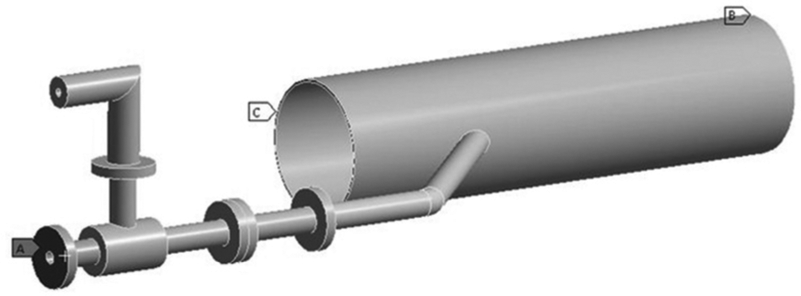
3D model for simulation.
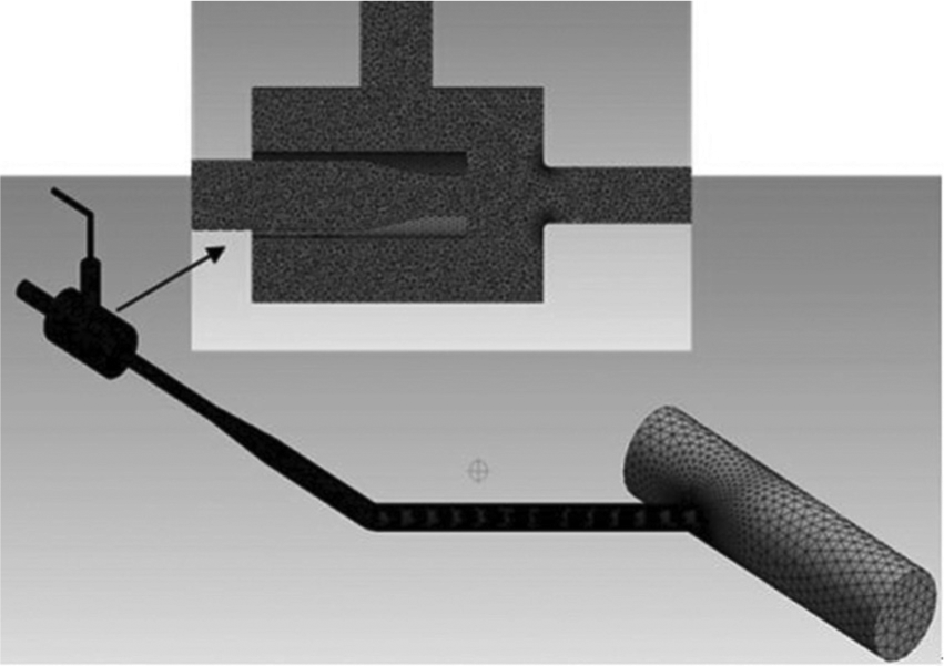
Meshes for simulation.
Simulation model and port definition.
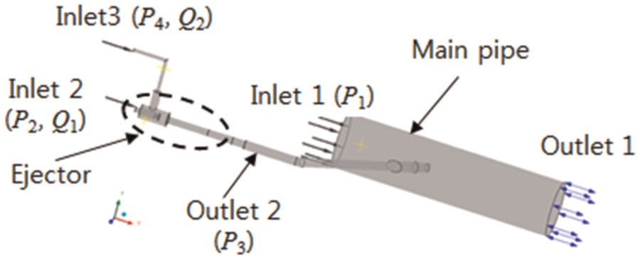
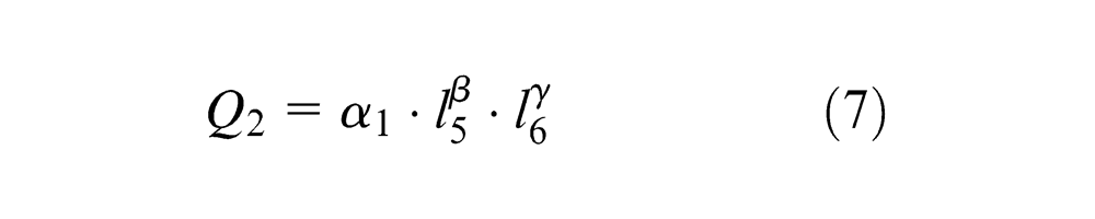
The simulation results are presented in Table 2 and Figure 5. As shown in simulation results, every case can entrain the air over 10 mm3/h according to change of the parameters l5 and l6. They satisfied the design requirement. Based on the simulation results, we induced the specific model to represent the relationship between the amount of suction and variation of parameters of l5 and l6 using the nonlinear least squares curve fitting method. The induced function is presented in equation (1)
Simulation results.
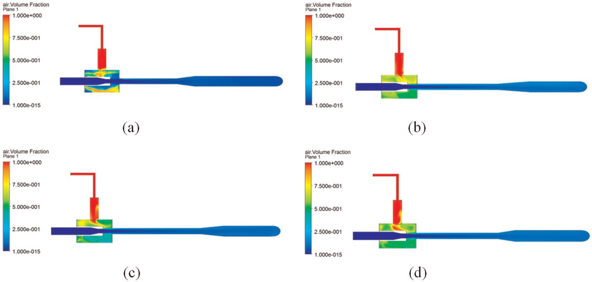
Simulation results for entrainment of the air volume: (a) case 1, (b) case 3, (c) case 6, and (d) case 8.
Analysis of production
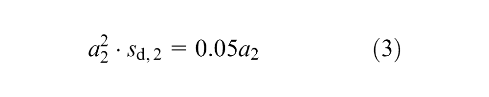
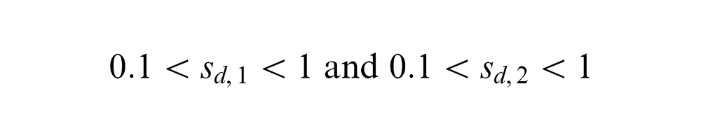
The two main procedures to produce the diffuser part of ejector are a tube expanding and tapering, as shown in Figure 2. These procedures need long cutting tool, and it takes a longer time to manufacture the diffuser part. The simple schematic diagram to produce the diffuser part is presented in Figure 6. As presented in previous section, the lengths of l5 and l6 in diffuser part are not significant parameters to affect the performance, but they should be manufactured within the specific tolerance. Actual manufacturing method is sketched in Figure 7. As shown in Figure 7, because of a long cutting tool, the rotary processing makes the vibration according to the conditions of the depth of cut (a) and infeed rate (sd). Especially, a large vibration makes taper cutting not performed anymore because the tool is bended without cutting of material. In this reason, we arranged the several machining conditions and checked the feasibility of machining. At this time, the machining expert checked the condition of cutting tool. To find the feasible cutting condition for tube expanding, the depth of cut (a1) is set up, that is, from 0.1 to 4 mm with infeed rate (sd,1), which is gradually increased for each condition of depth of cut (a1). In the same manner, the depth of cut (a2) for tapering is set up from 0.1 to 2 mm with gradually increased infeed rate (sd,2).
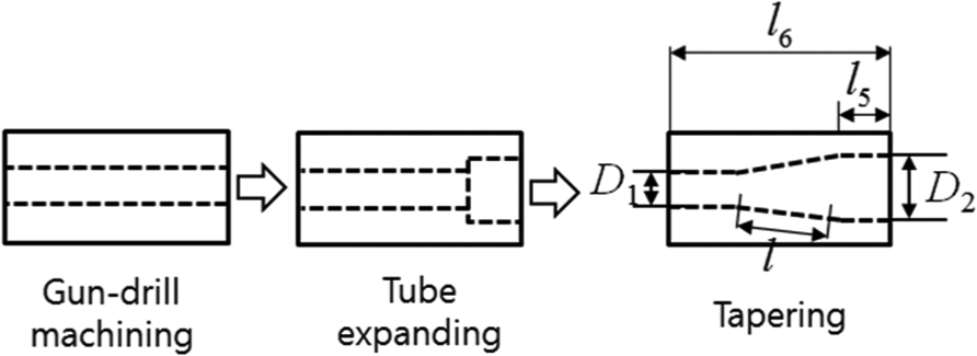
Production sequence for diffuser.
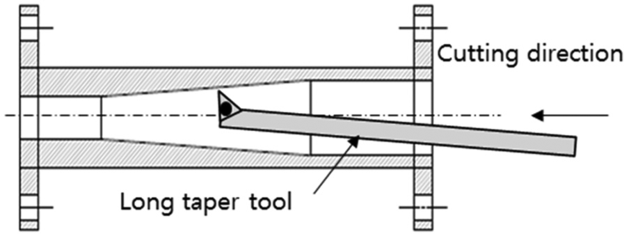
Simple schematic representation for tapering with long cutting tool.
The experiments results are represented in Figures 8 and 9. Based on the experimental result, the boundary equations to be cut are induced as represented by equations (2) and (3)
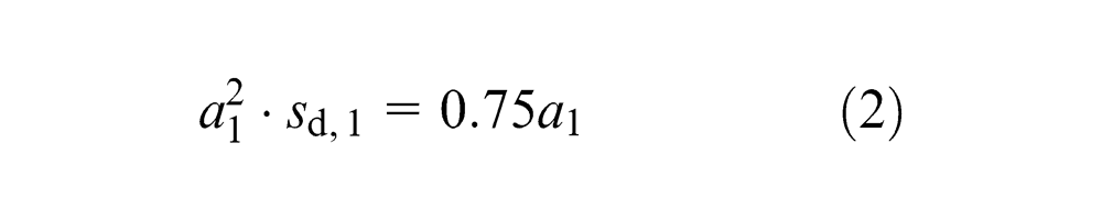
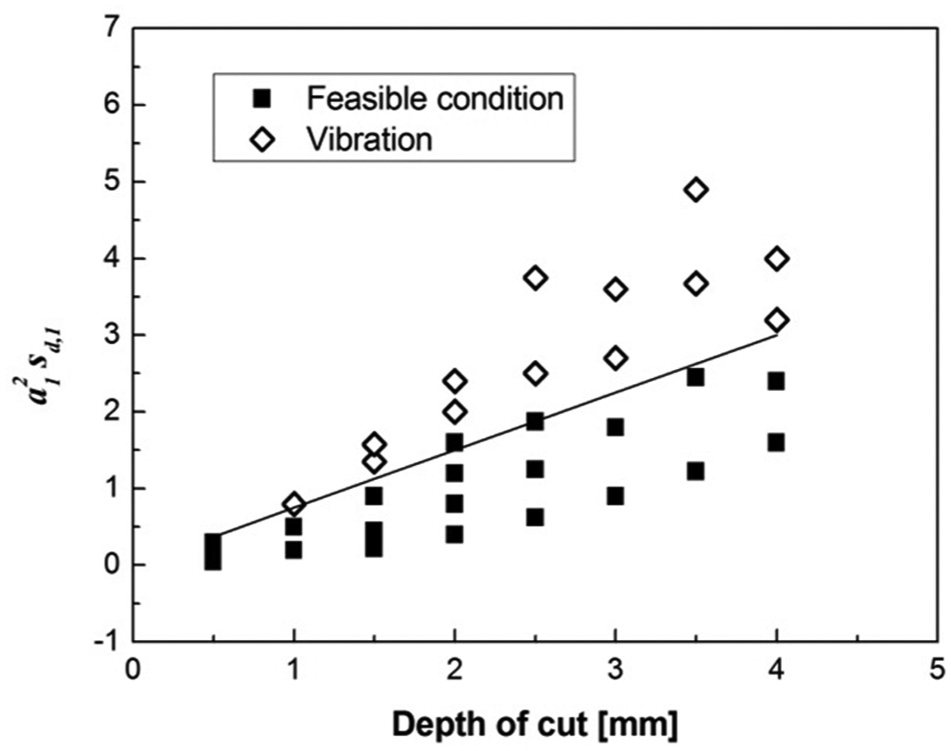
Feasible machining condition for tube expanding.
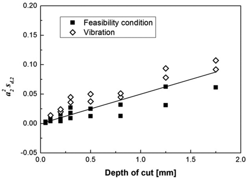
Feasible machining condition for tapering.
Design of the optimization algorithm
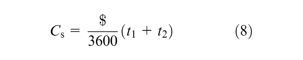
In the previous section, we induced the function for entrainment performance represented in equation (1) and boundary equation for feasible machining condition represented in equations (2) and (3). Based on equations (1)–(3), the optimizing method to find manufacturing conditions of lathe and the length dimension of expanding tube and tapering are proposed. Manufacturing condition is directly connected with production costs, and the length of expanding tube and tapering are related with manufacturing constraints. Therefore, an evaluation function for optimal condition is considered with the production cost and the entrainment performance. In order to define the evaluation function for production cost, the manufacturing time in accordance with machining conditions is calculated. The manufacturing time for tube extending and tapering can be calculated using the truncated area as represented in equation (4). And the total cycle times for each process can be calculated as represented in equation (5)
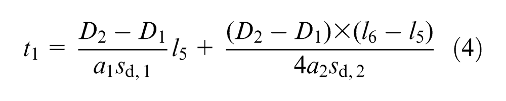
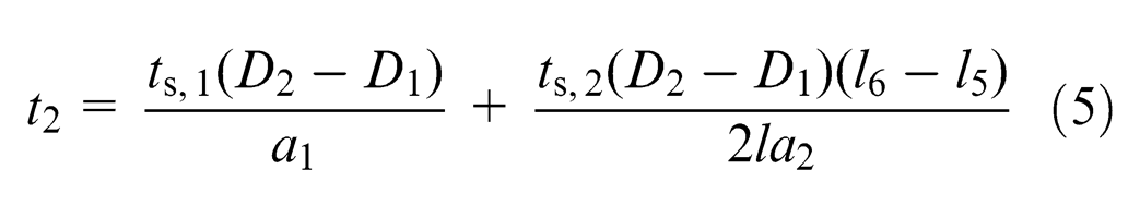
where D1 and D2 are diameters of inner and outer of tube, respectively; a1 and a2 are depths of cut for tube expanding and tapering, respectively; sd,1 and sd,2 are infeed rate for tube expanding and tapering, respectively;
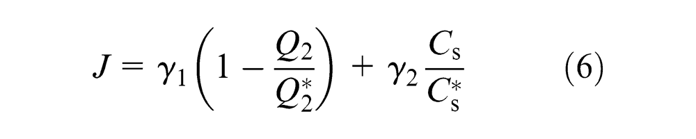
Based on these considerations, the proposed evaluation function is designed as represented in equation (6), and the constraint functions are used in equations (2) and (3)
where
where
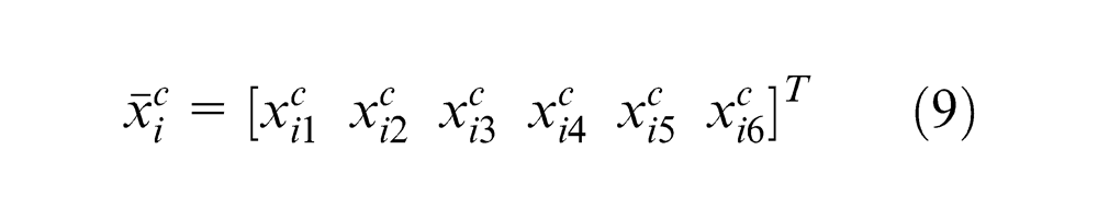
In order to solve the evaluation function, differential evolution (DE) algorithm is used in this article. The state variable for the DE is defined as
where
The offspring is generated through mutation of randomly selected three parents. The mutation operation is as follows
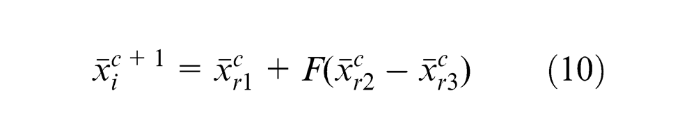
where
After mutation operation, recombination operation is performed to secure the diversity of population. Recombination operation shuffles
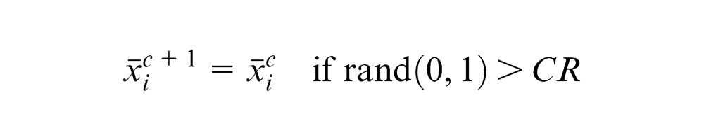
where
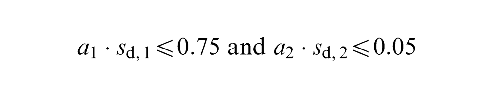
Finally, excellent traits are selected as next generation after evaluating the recombined offspring. During optimization of the evaluation function, we considered the machining constraints as follows:
Length of tube (mm)
Depth of cut (mm)

Feed rate (mm/s)
Feasibility constraint
Optimized result and evaluation
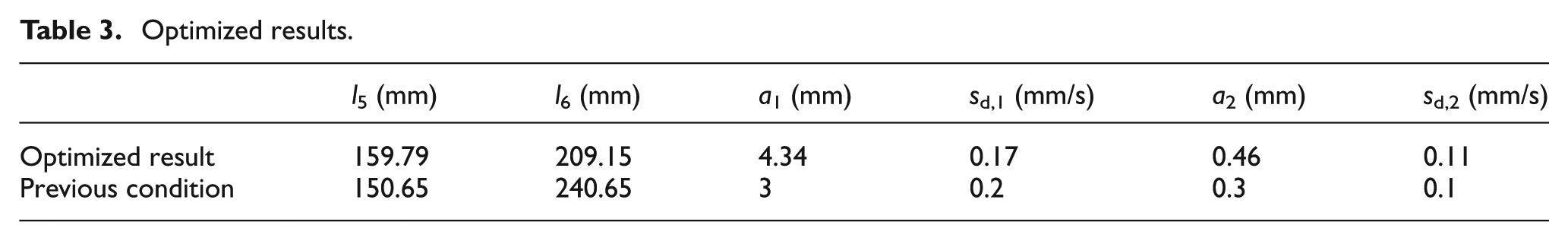
The proposed optimization algorithm is implemented using the LabVIEW software, as shown in Figure 10. The first generation for DE seeded 100 candidate parameters randomly. Each design parameter for DE, that is, F and CR, was selected as 0.1 and 0.25, respectively. The optimized results and previous manufacturing condition, dimension, and manufacturing control parameters are represented in Table 3.
Optimized results.
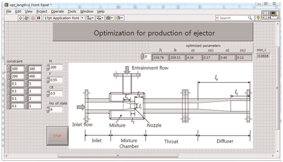
Implemented optimization algorithm.
When the previous machining condition gave the manufacturing time about 9 h, the optimized machining condition provided about 4.4 h. It reduced the lead time about 4.6 h.
In order to verify the optimized results, the performance of entrainment was compared with the original ejector and the changed dimension ejector. The dimensions l5 and l6 of original ejector used in the experiments are 150.65 and 397.65, respectively. The experimental equipment is set up, as shown in Figure 11. To compare the entrainment of air through inlet 3 (Q2), the pressure of inlet 1 (P1) and the flow rate of inlet 2 (Q1) are arranged at 0.4 MPa and 90 m3/h using manually operated butterfly valve. After setting these conditions, the pressures of the front and back of ejector were compared. The measured data of P1, Q1, P2, and P3 are represented from Figures 12–15. At this time, the amount of entrainment flow through inlet 3 was compared, as shown in Figure 16. As shown in figure 6, the average values of two cases are 12.39 and 12.96 m3/h. Also, the negative pressures during entrainment are measure after closing the inlet 3. The measure result is represented in Figure 17. Through the experiments, it is found that the proposed method can guarantee the performance and reduce the manufacturing cost, and equation (1) is valid when all other geometric parameters are constant and the entrained fluid is air.
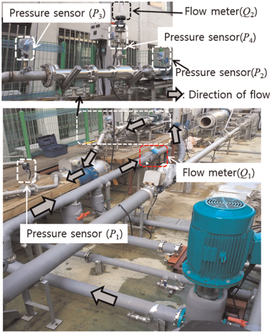
Experimental equipment for ejector.
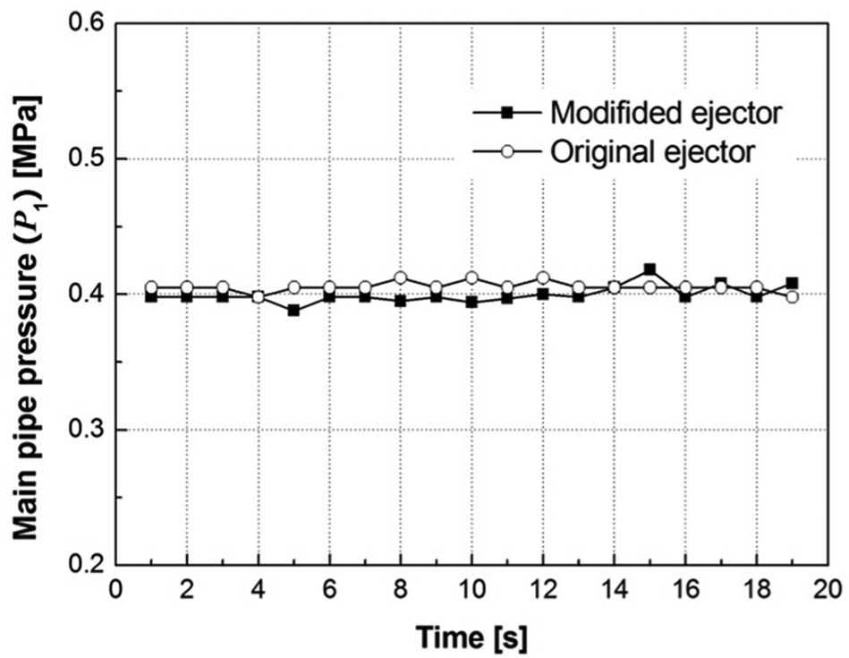
Pressure of inlet 1 of main pipe.
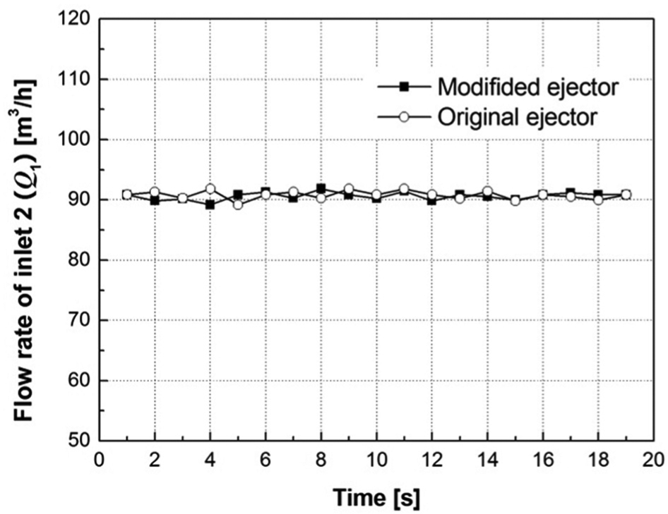
Flow rate of inlet 2 of ejector.
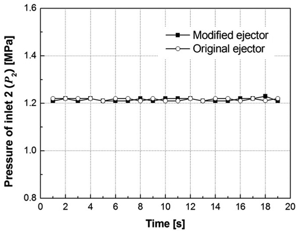
Pressure of inlet 2 of ejector.
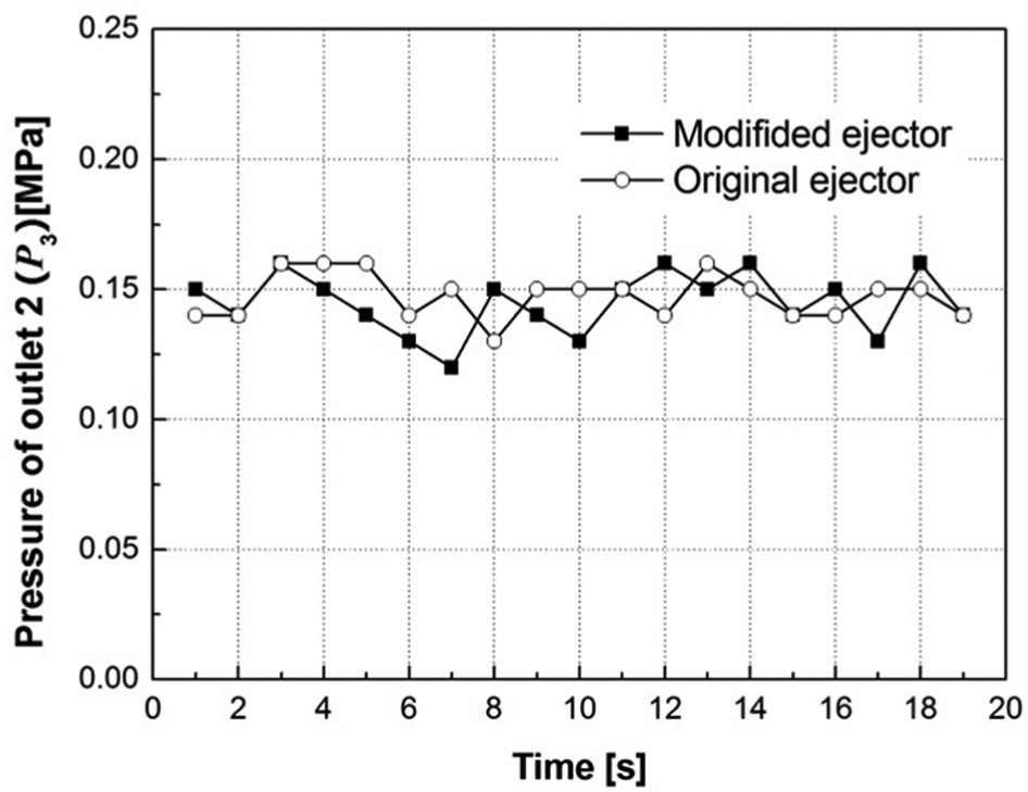
Pressure of outlet 2 of ejector.
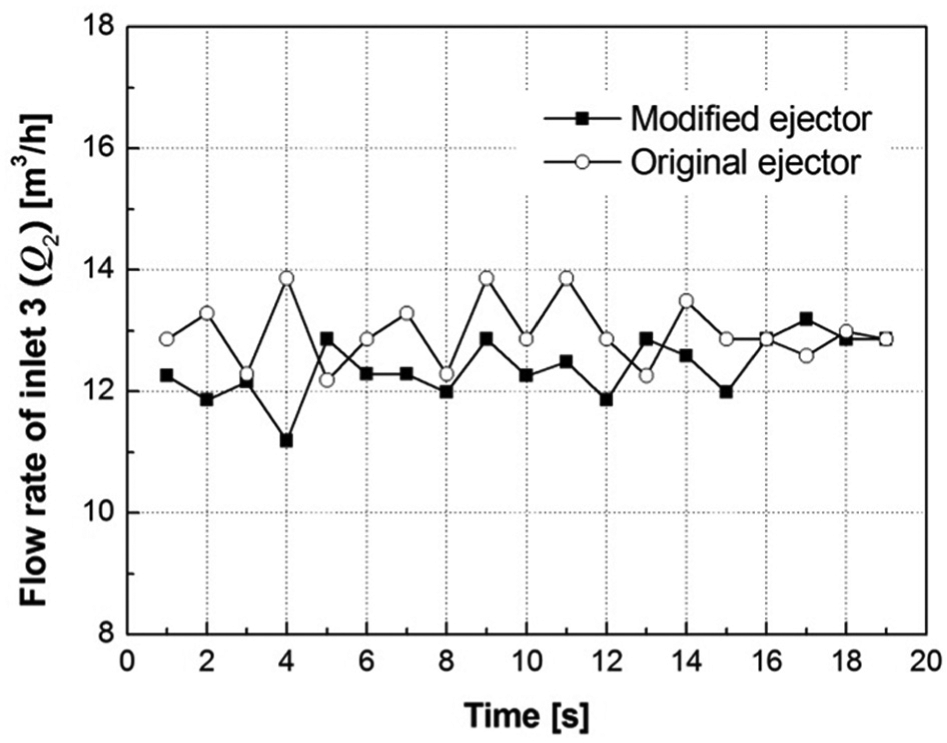
Flow rate of inlet 3 of ejector.
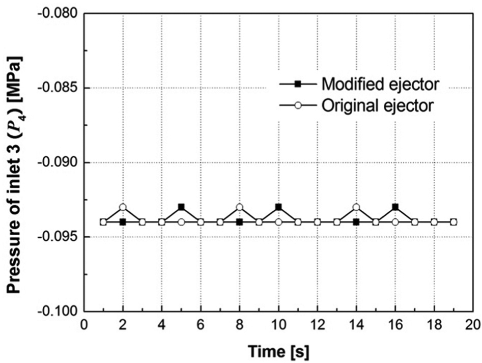
Pressure of inlet 3 of ejector.
Conclusion
The ejector used to the ballast system roles to entrain the ozone, which is to clean the polluted seawater. In order to guarantee the performance of ejector, lots of design parameters and manufacturing dimensional tolerance should be considered. In this article, we proposed the optimal method to reduce the production cost with satisfactory of entrainment performance. The proposed method was to design the evaluation function, which consisted of the two terms to represent the entrainment performance and production cost. The term of entrainment performance is induced based on the computer simulation results, and the term of production cost is induced through experimental data with the help of expert engineer. The optimized result is evaluated through experiments with previous ejector and the manufactured one based on the proposed method. Through the experiments, it is found that the proposed method can guarantee the entrainment performance and could reduce the manufacturing cost.
Footnotes
Appendix 1
Declaration of conflicting interests
The author declares that there is no conflict of interest.
Funding
This study was supported by the Dong-A University research fund.