
Abstract
A piezoelectric polyvinylidene fluoride film stress sensor was developed to measure the contact pressure on the sheet near the cutting edge in the fine-blanking process. Two cases with and without cracks in the fine-blanking surface were studied. The relationship between the contact pressure and crack width was investigated using the Kriging methodology at different punching speeds. The maximum contact pressure appeared at the beginning of sheet punching, but not at the end of V-ring indention. For the case with and without cracks in the fine-blanking surface, one and two fluctuations of contact pressure are observed, respectively. Using the Kriging model, a fine-blanked surface with a reduced crack width can be obtained using the optimal values of contact pressure and punching speed.
Introduction
The fine-blanking process produces accurate near-net shape parts requiring fewer process steps at lower cost than the conventional blanking process, which are widely used in automotive and electrical industry.1,2 For the successful operation of the fine-blanking process, the V-ring indenter and blank-holder force play important roles in establishing high hydrostatic compressive stress in the metal in the shearing zone. The application of the V-ring indenter increased the hydrostatic compressive stress. 3 High hydrostatic compressive stress was important for the prevention of crack formation. 4 The crack width in the fine-blanking surface decreased as a result of using optimal parameters of the V-ring indenter5,6 and the blank-holder force. 7
The blank-holder force is calculated from the hydraulic pressure in the hydraulic cylinder, which is the entire effect of the blank-holder on the sheet. 8 However, the contact pressure is not uniform at the contact surface because of the curvature, wrap and elasticity deformation of the metal sheet. According to the experimental result, 9 the strong contacted area was in the neighbourhood of the blanking contour when using the blank-holder without the V-ring indenter. Outside of this contacted area, the blank-holder weakly contacted the blanked sheet. When using the blank-holder with the V-ring indenter, the contact pressure would increase significantly on the contact surface, and this was caused by pressing the V-ring indenter into the sheet. However, in the case with the V-ring indenter, limited studies have been carried out to reveal the change characteristics of the contact pressure near the cutting edge and its effect on crack width in the fine-blanking surface.
In previous studies,10–12 the contact pressure in metal-forming processes was measured using pin-type sensors. This conventional pressure sensor requires considerable space to be installed, but there is limited space to install the sensor near the blanking clearance in the fine-blanking die. In addition, the hole drilled near the blanking clearance for the installation reduces the strength of the die and increases the risk of cracking in the fine-blanking process. However, film piezoelectric sensors, which can be pasted directly onto the surface, offer minimal disturbance to the testing environment due to their mechanical flexibility, high piezoelectric coefficients, dimensional stability, low weight and chemical inertness.13,14
This study develops a tailor-made polyvinylidene fluoride (PVDF) film stress sensor for the measurement of the pressure on the contact surface of the sheet near the blanking clearance in the fine-blanking process. The characteristics of the contact pressure variation were compared between the two fine-blanking processes that form the fine-blanking surface with and without cracks. The main objective is to reveal the crack formation process that is reflected in the contact pressure variation. Also, the effect of the contact pressure on the crack width was also addressed by constructing the Kriging model.
Experimental methods
PVDF material
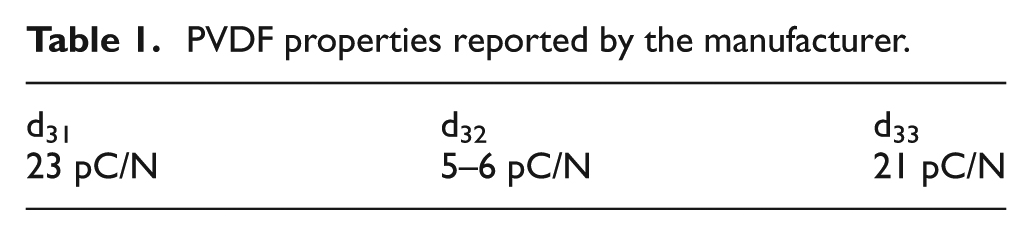
PVDF is a semi-crystalline piezoelectric polymer with approximately 50%−65% crystallinity. 15 The chemical structure is given by (CH2–CF2)n. 16 During the manufacturing process, the PVDF resin pellet is made into a sheet form with a melt extrusion, and the sheet is stretched. PVDF is an anisotropic material, and its electrical and mechanical properties thus differ depending on the direction of the external force in the material. The piezoelectric coefficients, dij and gij , which are the charge and voltage coefficients, respectively, possess two subscripts. The coefficients are related to the electric field produced by the mechanical stress. The first subscript refers to the electrical axis, and the second refers to the mechanical axis. The axes may be 1, 2 or 3, corresponding to the length, width and thickness; Axis 1 refers to the stretching direction, Axis 2 refers to the perpendicular planar direction and Axis 3 refers to the poling axis, which is perpendicular to the material surface. However, since the electrodes are on the top and bottom of the film, the electrical axis is always 3. The mechanical axis may be 1, 2 or 3 since the stress can be applied to any of these axes. The piezoelectric coefficients are shown in Table 1. The actual shear coefficients d 15 and d 24 are not considered in this study because their value is negligible.
PVDF properties reported by the manufacturer.
Design of film stress sensor
The sensor was implemented using commercial PVDF material. The thickness of the film was chosen to be 50 µm with silver ink metallization. The developed PVDF sensor consists of two main components: the piezoelectric PVDF film and the insulation films coated with the circuit made of silver ink metallization. To implement a sensor element, a 5 mm × 5 mm piece of material was cut from a commercial piezoelectric PVDF film. The flexible printed circuit (FPC) films were prepared. The circuits were drawn on the polyethylene terephthalate (PET) films using the screen printing technique with conductive silver ink. As shown in Figure 1, the piezoelectric PVDF film used as the sensing element was placed between the two FPC films. 17 Double-sided tape was used to attach the sensor elements together. The double-sided tape provides a uniform layer between the sensor elements. The thickness of the sensor was 0.29 mm. The disturbance to the testing environment caused by the sensor installation is negligible.
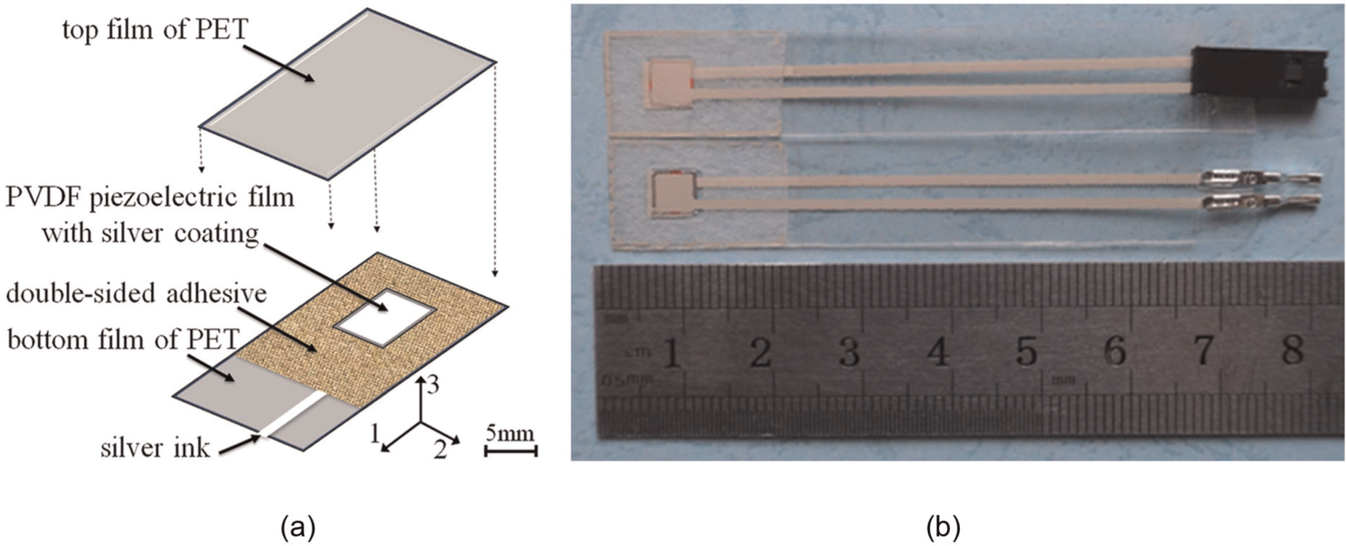
PVDF film stress sensor: (a) structure of film stress sensor and (b) film stress sensor.
The piezoelectric PVDF film can measure the pressure in the fine-blanking process because the charge generated on the electrodes by straining the foil discharges slowly. The stress changes that have a minimal frequency of about 0.01 Hz can be measured. The frequency of the fine-blanking process is about 1 Hz, and the PVDF stress sensor can therefore be used to detect the pressure change. When a pressure change is applied to the sensor, the PVDF film is strained, and due to its piezoelectric properties, an electric charge and voltage are generated on the electrodes. This electric signal is measured with a simple electric circuit. The voltage as the output signal was recorded by a resistor–capacitor (RC) integrator circuit, which was shown on the screen of the oscilloscope (Tektronix TDS 2014B). The compressive pressure that is vertical to the sheet surface was dominant after the V-ring was pressed into the sheet. The strain of the PVDF film was mainly in the three directions (Figure 1). Because there was no heating during assembly of the sensor, the adverse effects on the accuracy caused by the thermoelectric effect can be ignored. 18 The film stress sensor is suitable for monitoring the contact pressure on the sheet surface in the fine-blanking process.
Calibration of film stress sensor
There is a linear relationship between the normal applied load and the output voltage under the condition that the friction coefficient is constant. 19 The split Hopkinson pressure bar (SHPB) technique was used for the calibration of the film stress sensor. The strain gauge was used as the calibration standard to determine the value of the contact pressure on the sensing element of the film sensor. The calibration model is written as follows
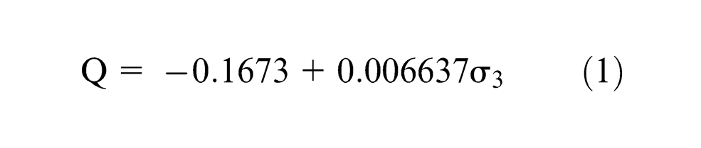
where σ3 is the contact pressure (MPa) applied on the sensing element of the film stress sensor and Q is the generated charge per square millimetre (µC/mm2) of the film stress sensor. Figure 2 shows the calibration results. The analysis of variance (ANOVA) shows that the contact pressure has a significant linear relationship with the electric charge (i.e. F0 > F1, 7, 0.99). The value of R 2 for the calibration model is 98.5%, which indicates that 98.5% of the variation of the output can be explained by the calibration model. Therefore, the calibration model is considered to be the best fit.
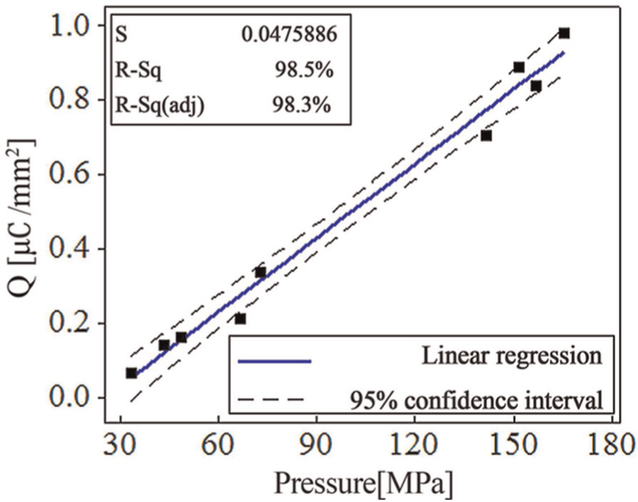
Calibration of the PVDF film stress sensor.
The output signal of the film stress sensor was measured by an RC integrator circuit consisting of a capacitor (47 nF) and a resistance (30 Ω). The electric charge generated on the film surfaces can be calculated by the following equation

where Q is the generated electric charge (C), C is the capacitance (F) of the electric circuit and U is the output voltage (V) of the film stress sensor. The capacitor voltage, which is the output voltage of the film stress sensor, is measured by the oscilloscope (Tektronix TDS 2014B). Then, the value of Q can be determined. Therefore, the contact pressure can be calculated by equation (1), according to the value of Q obtained.
Installation of film stress sensor in fine-blanking die
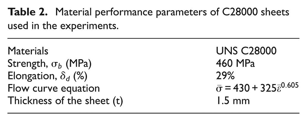
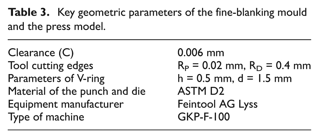
The film stress sensor was placed at the contact surface of the sheet near the clearance to measure the contact pressure in the fine-blanking process. Table 2 shows the mechanical property of the C28000 sheet used in the experiments. Table 3 shows geometrical parameters of the fine-blanking die and the model of the press. The V-ring was first pressed into the sheet, and the sheet was then punched. Figure 3(a) shows the locations of the film stress sensors (I–III) on the fine-blanking die. As shown in Figure 3(a) and (b), the film stress sensor I on the upper surface of the sheet was used to determine the time at which the punch contacted the upper surface in the punching process. The film stress sensor II was placed over the blanking clearance to determine the time at which the punch reached the lower surface of the sheet. The time length of the sheet punching process can be determined according to the two time points. The punching speed was calculated by dividing the sheet thickness by the time length under the assumption that the punch moved at the same speed. In order to install the film stress sensor II, the sheet did not cover the cutting contour of the die completely. The area of the cutting contour uncovered by the sheet was so small that its influence on the punching speed is considered to be negligible. Figure 3(a) and (c) shows the installation of film sensor III for the measurement of the contact pressure at the contact surface of the blank-holder and sheet in the fine-blanking process. In Figure 3(a), f represents the plastic film that was laid adjacent to the film sensor to offset its protrusion caused by the sensor installation. Each experiment was replicated three times, and the average value was recorded.
Material performance parameters of C28000 sheets used in the experiments.
Key geometric parameters of the fine-blanking mould and the press model.
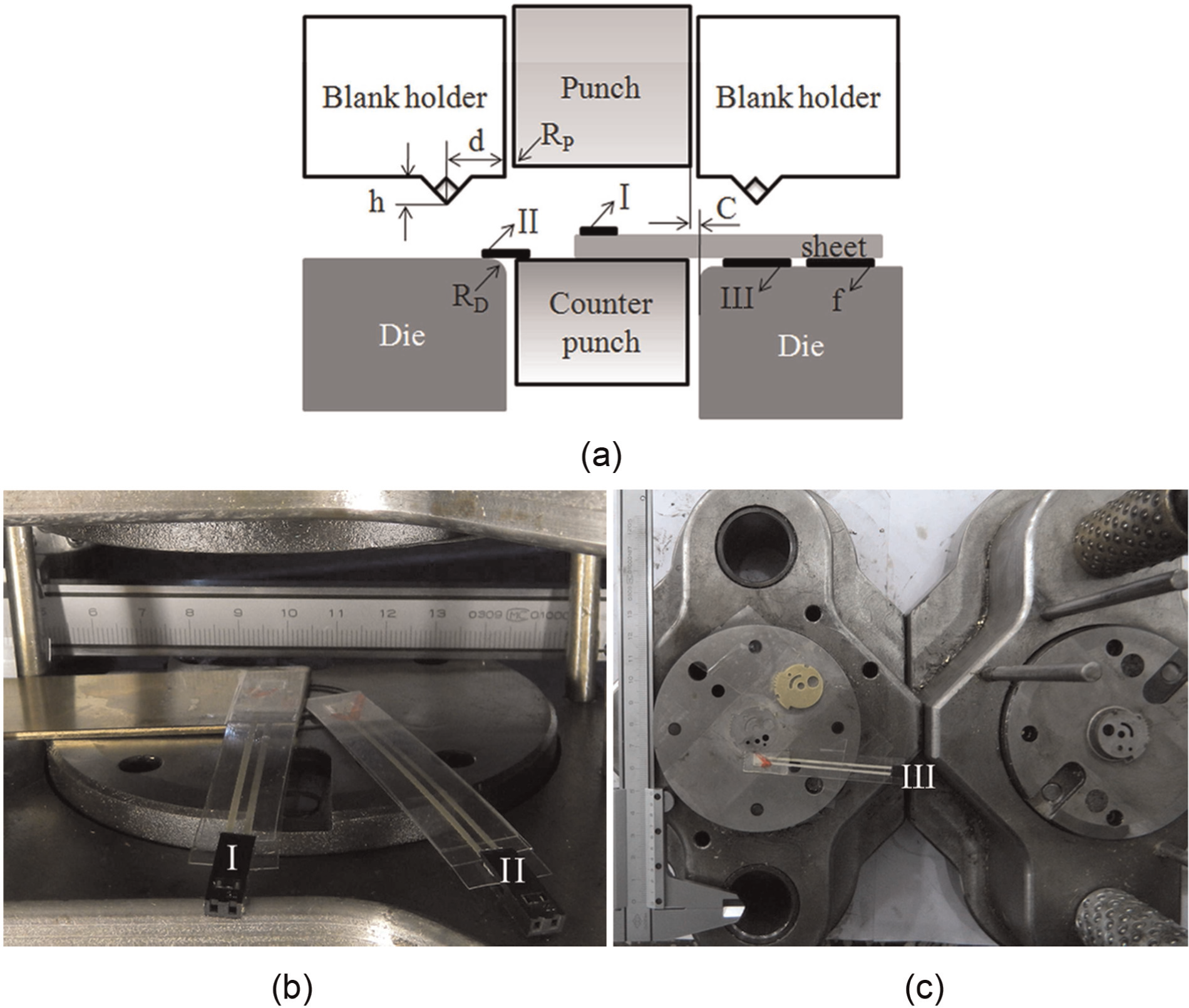
Measurement of contact stress and time length of sheet punching: (a) locations of the measurement using the film stress sensors (I–III), (b) installation of film stress sensors (I and II) to determine the time points of contacting upper and lower surfaces and (c) installation of film stress sensor (III) for measuring contact stress.
The advantage of this method is that the input of the film stress sensor is related to the contact pressure distribution on the contact surface. It overcomes the disadvantage that exists when the input is the force, which is the required conclusion based on the specific size of the contact area of the blank-holder and sheet. The contact pressure can be used as an indicator of the blank-holder force and V-ring indenter parameters to evaluate their effect on the crack in the fine-blanking surface. Therefore, a general and detailed understanding can be obtained.
Meta model–based on Kriging method
The conventional trial-and-error method and empirical approaches are time-consuming when designing fine-blanking dies. These methods are associated with higher costs, lower efficiency and design inaccuracies. Because of these deficiencies, there is a need for a more reliable and better design approach. Application of a meta-model is proposed to reduce the cognitive load on the designer. The proposed methodology helps to select the set of optimal parameters to be used. There are several methods, including the response surface methodology (RSM), Taguchi method, neural networks (NNs), inductive learning and Kriging, which can be used to construct a meta-model for the relationships between the inputs and outputs over the range of interest.
The polynomial based RSM is the most widely used meta-model. 20 RSM, which is based on experimental programming, normally requires the assumption of the order of the approximated base function. This will sometimes be difficult because it requires an understanding of the qualitative tendency of the entire design space. Instabilities may arise when higher order response surfaces are used to model a non-linear design space. In addition, the amount of data used to estimate all of the coefficients determines the order of the polynomial. 21 However, it may not be possible to obtain enough samples to estimate all of the polynomial coefficients in practice, particularly in high dimensions. The Taguchi method is easy to perform to obtain the optimal condition. However, the optimal condition is the best combination of given levels of the factors and is not the optimal solution in the design space. 22 The model based on NNs requires many sample points for the training, which is a practical difficulty. 23 The other problem when using NNs is the need for the operator to be skilled or experienced. 24
The Kriging method 25 is a method of spatial prediction that is based on minimizing the mean error of the weighting sum of the sampling values. There is no need for an assumption related to the order of the base function for approximation during the process of model building, which is superior to that of RSMs. The Kriging method involves only parameter optimization for three variables to determine a model and results in lower computational costs for the model generation. It is also superior to NN approximation, which requires a high computational cost for learning.
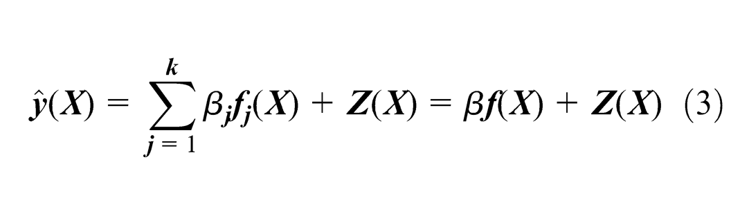
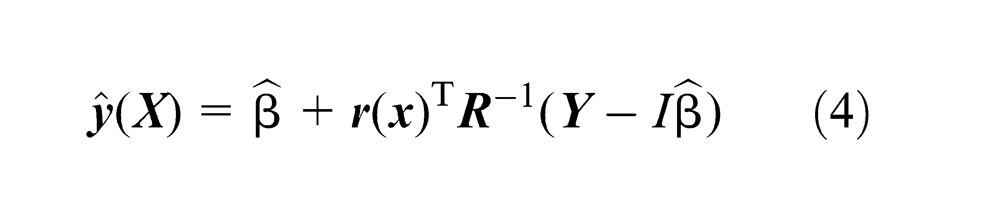
The Kriging method was originally developed in geostatistics as a statistical interpolation method to estimate mineral concentrations over an area of interest. 26 The mathematics was further developed as an interpolative approximation based on an exponentially weighted sum of the sample data. 27 Kriging models are very flexible because of the wide range of correlation functions that can be chosen to build the model. The Kriging model was applied early to model the mechanical behaviour and phenomena of the shape memory alloys.28,29 It is a semi-parametric interpolation technique, which estimates the unknown information at one point according to the known information. 30 A flow chart of the design process is shown in Figure 4. Sample points were selected using the uniform design (UD) as the experimental design. The average value of the three repeated experiments was used in constructing the Kriging model. The approximation of the original model can be expressed as the following formula under the conditions of multiple inputs and a single output30,31
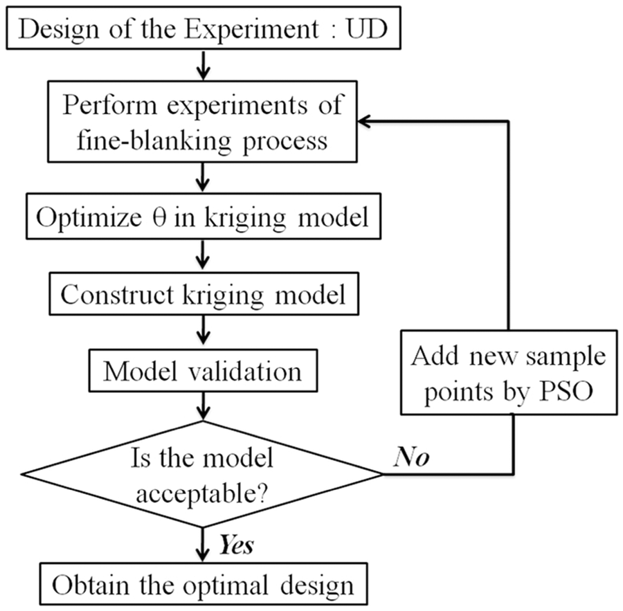
Steps to construct approximate model.
where
Let k = 1 and
where
The mean squared error (MSE) of this predictor is minimized with unbiased estimation. The quality of the Kriging model can be assessed according to the accuracy of the prediction of the original model at unobserved locations.
New sampling points were required if the obtained Kriging model is not acceptable. The particle swarm optimization (PSO) is a population-based heuristic global optimization technology. 35 The idea of the PSO algorithm is based on the simulation of simplified animal social behaviours. The PSO algorithm became popular 36 due to its effectiveness in difficult optimization problems, as well as because of its ease of implementation and its ability to quickly converge to the good solution.
Experimental results and discussion
Characteristics of the curves of contact pressure
Figure 5 shows the contact pressure measured at the contact surface of the blank-holder and sheet near the blanking clearance in the fine-blanking process. The moment at which the punch contacted the upper and lower surfaces of the sheet can also be determined. Figure 6 shows the curve of the contact pressure versus the time in the fine-blanking process and the corresponding clean-cut surface. The punching speed is about 4 mm/s. The first fluctuation of the contact pressure was caused by pressing the V-ring indenter into the sheet. The second fluctuation occurred during the punching process. The maximum contact pressure occurs at the beginning of punching. Then, the value of the contact pressure shows a decreasing trend with an increase in time. The maximum contact pressure in the punching process was about five times higher than that caused by pressing the V-ring indenter into the sheet. This indicates that the direct contribution of the blank-holder force is limited when increasing the contact pressure during the punching process. The increase in the contact pressure is mainly and directly from squeezing the metal by punching in the shearing zone. However, applying a high blank-holder force can minimize the increase in the sheet thickness near the clearance during the punch penetration. These two factors lead to an increased hydrostatic compressive stress in the metal between the cutting edges of the die and the punch, which prevents crack formation during the punching process.
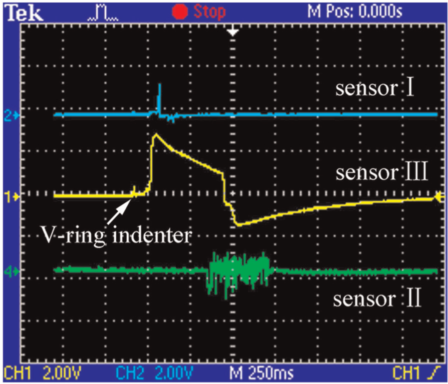
Output of the film stress sensors in fine-blanking process.
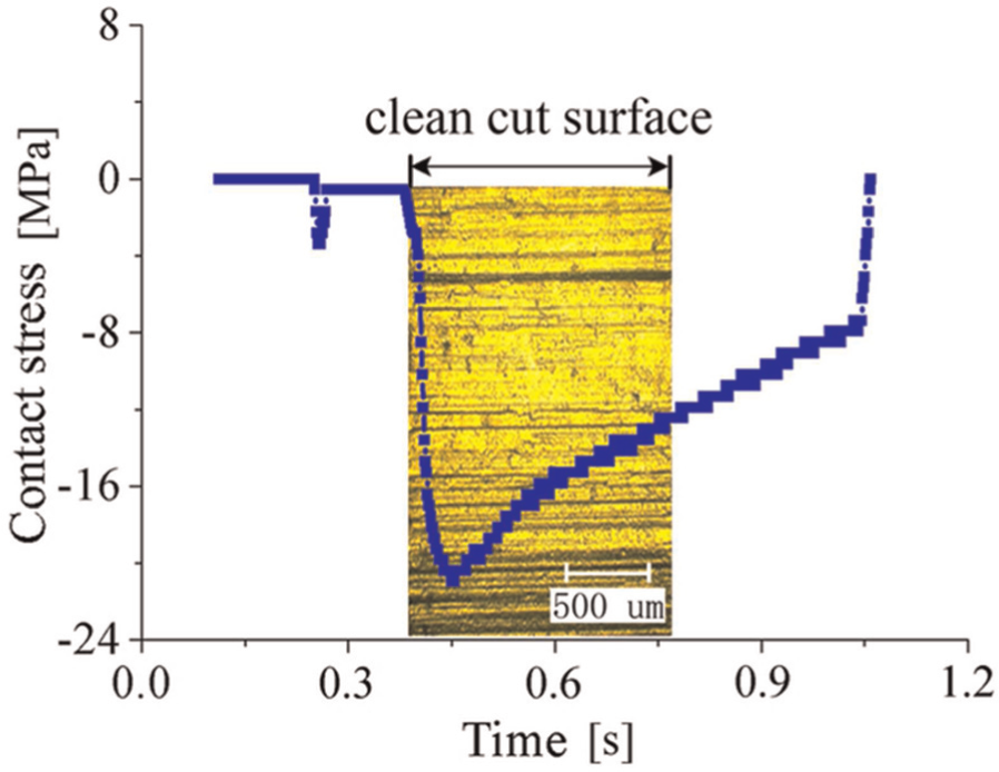
Clean-cut surface and the corresponding contact stress.
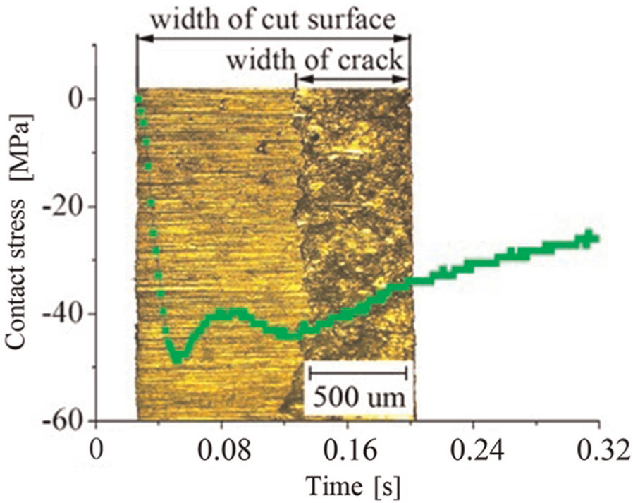
Figure 7 shows the fine-blanking surface with cracks and the corresponding curve of contact pressure versus the time. The burnish zone is on the left side, while the crack zone is on the right. The process of generating a new fine-blanking surface is in the positive time direction. This fine-blanking surface with cracks was obtained using a lower blank-holder force and faster punching speed than in the case, which generated the clean-cut surface. The punching speed is approximately 11 mm/s. The maximum contact pressure in the punching process (Figure 7) is smaller than that in the fine-blanking process, which obtained the clean-cut surface (Figure 6). In the process that formed the clean-cut surface (Figure 6), the contact pressure decreased smoothly and monotonically until the punch reached the lower surface of the sheet. However, two troughs are observed in the process, which formed the fine-blanking surface with cracks (Figure 7). The punching speed is assumed to be constant during the punching process. The sheet thickness corresponds to the time lengths of the sheet punching. The crack ratio is the ratio of the crack width to the width of the cut surface. The time at which the crack occurred was the crack ratio multiplied by the time duration of sheet punching. It was found that the second trough occurs almost simultaneously with the crack generation (Figure 7). Before the appearance of the crack, the contact pressure first decreased and then increased. After the occurrence of the crack, the contact pressure increased until the end. The second trough can be attributed to the crack generation in the cut surface. The variation of the contact pressure reflects the change in the stress condition in the metal near the clearance in the punching process. The change in the contact pressure is caused by the combined effect of extruding the metal by punching, strain hardening and crack formation. The crack initiation and propagation also has a similar effect on the punch force during the punching process.8,9,37 As shown in Figures 6 and 7, a similar characteristic was found in the curve of the contact pressure. The maximum contact pressure occurs at the beginning of the punching sheet. The value of the contact pressure shows an overall decreasing trend as time increased until the punch reaches the lower surface of the sheet.
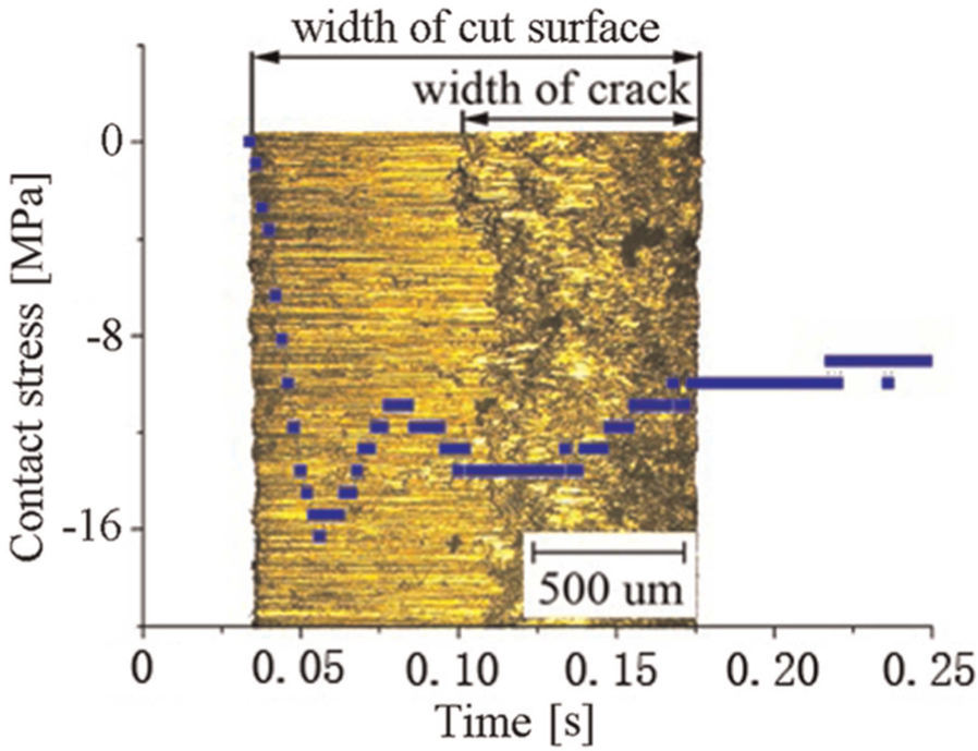
Relationship between crack generation and the contact stress variation.
The advantage in measuring the contact pressure can be found when compared with the measurement of the blank-holder force. In the experiments mentioned above, the hydraulic pressure in the blank-holder cylinder was also measured by an oil pressure gauge as the method used in the previous studies.8,9 The blank-holder force was calculated according to the hydraulic pressure using the active piston area of the corresponding cylinder. The measurement result of the blank-holder force in the fine-blanking process was shown in Figure 8. Curves of Forces 1 and 2 represent the blank-holder force in the fine-blanking processes, which made the cut surface without and with cracks, as shown in Figures 6 and 7, respectively. The value of the blank-holder force was not significantly changed and was nearly constant in the fine-blanking process. The crack generation in the punching process was not reflected in the curve of the blank-holder force. The details of the changes in blank-holder force cannot be obtained by measuring the hydraulic pressure in the cylinder. The loss of the signal may have been caused by the redundant transmission links in the blank-holder force measurement (Figure 9).
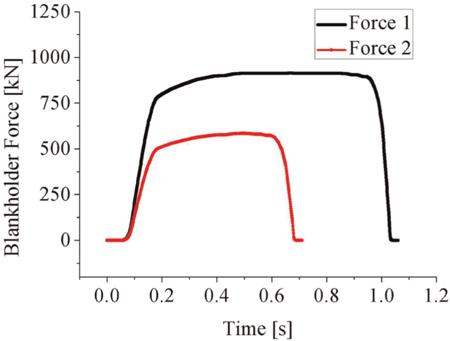
Blank-holder force in the fine-blanking processes.
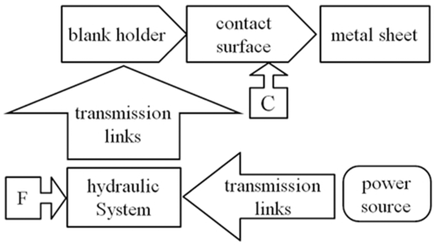
Difference between the measurement of blank-holder force (F) and contact pressure (C).
The findings enable us to understand the fine-blanking process. The relationship between crack formation and contact pressure provides the basis for the sensing method when monitoring the fine-blanking process, leading to the idea that the formation of cracks is related to the variation of the contact pressure at the contact surface of the sheet near the clearance. The information pertaining to the contact pressure can be utilized for process diagnosis and process optimization.
Optimization of crack ratio based on the Kriging model
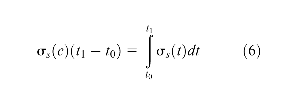
In this article, the Kriging model was built for the prediction of the crack ratio (the ratio of the crack width to the width of the fine-blanking surface) and to facilitate the design optimization of the contact pressure under different punching speeds. The contact pressure changes over time during the fine-blanking process (Figures 6 and 7). The contact pressure as a function of time is continuous for the closed interval [t 0, t 1]. The average value of σs (t) from t = t 0 to t = t 1 is the integral
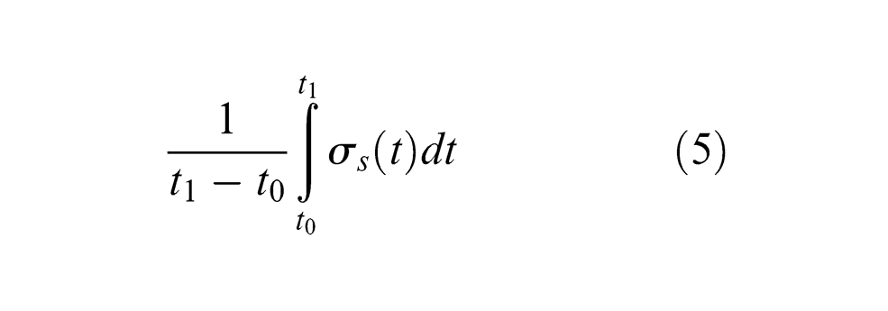
where σs
(t) is the contact pressure (MPa) on the contact surface of the blank-holder and sheet during the punching process, and
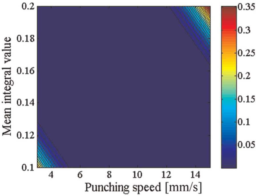
In the Kriging model, both the average value (i.e. σs (c)) and punching speed (mm/s) are taken as the input variables to predict the crack ratio. The contact pressure is adjusted by varying the blank-holder force. The range of the average value (i.e. σs (c)) is from 0.1 to 0.2, while the range of the punching speed is from 3 to 15 mm/s.
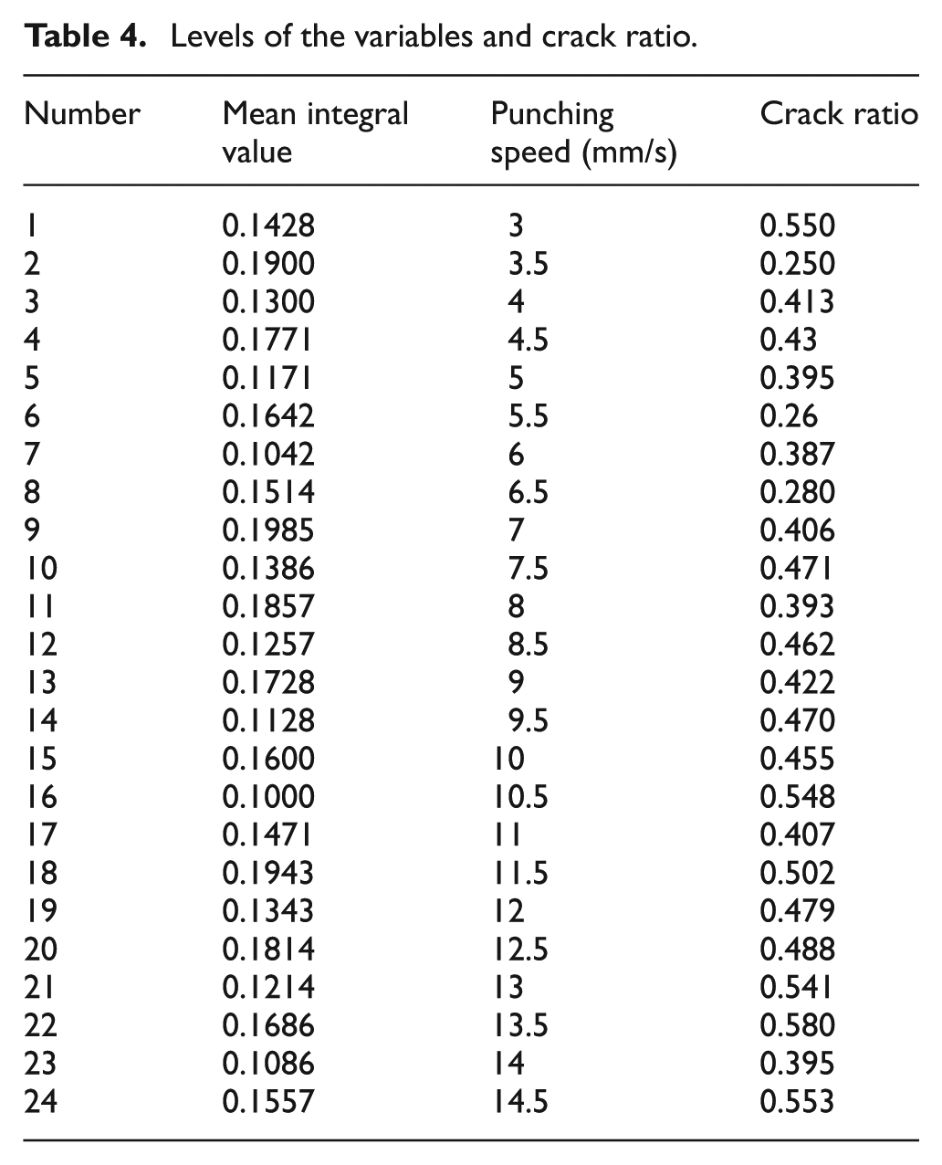
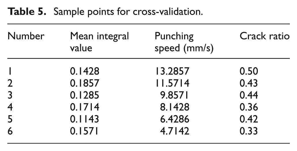
In this study, Uniform Design (UN) is used as the sampling method to obtain the training group to construct the Kriging model. Table 4 shows the levels of the factors and the crack ratio. Other experiments with six sample points in the design space were performed as a holdout group for the fivefold cross-validation, as shown in Table 5. In this study, both leave-one-out cross-validation and fivefold cross-validation were applied to select the best Kriging model. Figure 10 shows the contour of the established Kriging model. In the design space, the sample points marked by ‘•’ belonged to the training group. The sample points marked by ‘+’ were the holdout group for the fivefold cross-validation. In the Kriging mode, the optimized θ is 0.9742 and 0.4515 for the punching speed and average value of the integral of the contact pressure, respectively. Figure 11 is the MSE of the Kriging model. The value of MSE is small in the design space. The Kriging model can be used to predict the crack ratio on the fine-blanking surface. When the average value of the integral is 0.15 and the punching speed is 8.72 mm/s, the crack ratio is 42.7%. This predicted value was validated by carrying out the experiment under the same condition. The crack ratio obtained in the experiment was 42.5%, as shown in Figure 12. In the previous studies,38–40 it was found that the elongation at failure was less at a high strain rate than that at a low strain rate. In the fine-blanking process, the strain rate increased with the increase of the punching speed. Figure 10 shows that in most cases, the crack ratio is usually greater at higher punching speeds than at lower punching speeds. A small crack ratio can be obtained using an appropriate value of the punching speed and the average value of the integral. The minimum crack ratio appeared in the condition with the largest average value of the integral and the smallest punching speed. The result indicated that the average value of the integral of the contact pressure can be considered to be a factor when predicting the crack ratio for the fine-blanking process.
Levels of the variables and crack ratio.
Sample points for cross-validation.
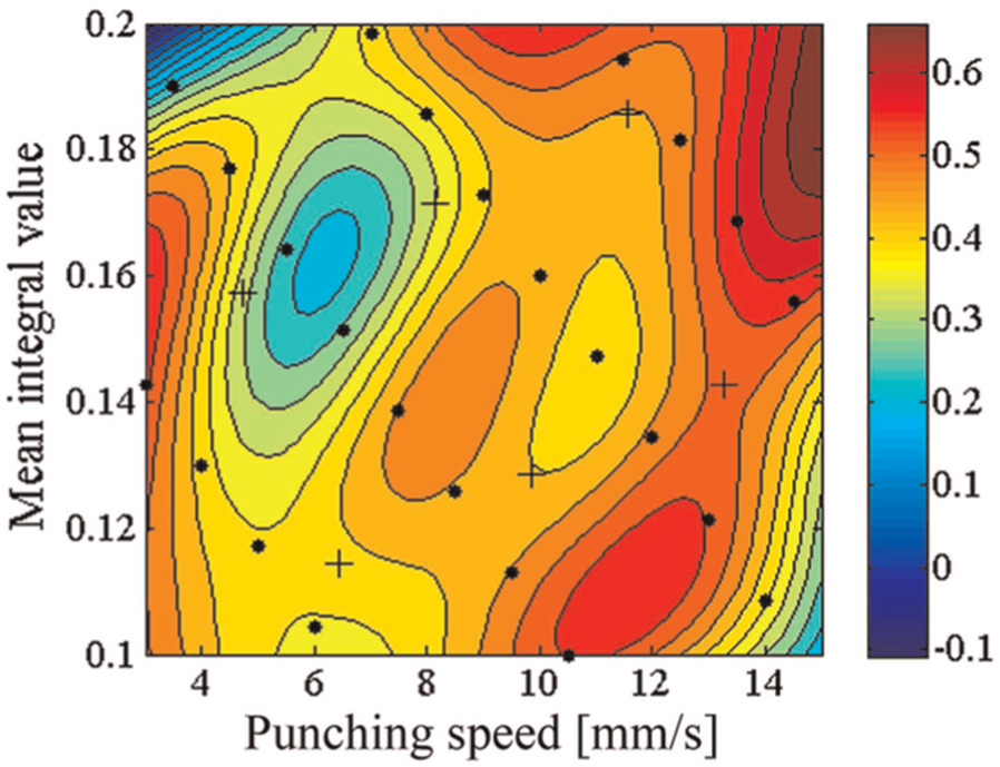
Contour of the Kriging model.
Distribution of the MSE of the Kriging model.
Fine-blanking surface with crack and the corresponding contact pressure curve.
Conclusion
In this article, a PVDF film stress sensor was developed to measure the contact pressure on the contact surface of the sheet with a blank-holder near the blanking clearance. The characteristics of contact pressure when forming the fine-blanking surface with and without cracks were determined. Based on the results, the following conclusions can be drawn:
The maximum value of the contact pressure occurred at the beginning of the punching sheet, which was about five times higher than that caused by pressing the V-ring indenter into the sheet. It indicated that the punch squeezing the metal in the shear zone is the direct and main reason for increasing the contact pressure in the fine-blanking process. In addition, the application of a high blank-holder force prevented the increase in the sheet thickness during the punch penetration. The following two factors increased the hydrostatic compressive stress in the metal near the blanking clearance:
The contact pressure decreased smoothly and monotonically during the sheet punching process, which forms the clean fine-blanking surface. In the punching process, which forms the fine-blanking surface with cracks, two troughs were found in the fluctuation curve of contact pressure. The second trough appeared at the same time that the cracks occurred in the fine-blanking surface. The non-linear relationship between the process parameters (i.e. contact pressure and the punching speed) and crack ratio was approximated using the Kriging method. It has been found that a high punching velocity usually leads to a large crack ratio. A fine-blanking surface with a small crack ratio can be obtained using the optimal value of the contact pressure and punching speed.
Footnotes
Declaration of conflicting interests
The authors claim that none of the material in this article has been published or is under consideration for publication elsewhere.
Funding
This research received no specific grant from any funding agency in the public, commercial or not-for-profit sectors.