
Abstract
This article describes automated identification, classification, division and determination of release direction of complex undercut features of die-cast parts. The proposed system uses the concepts of visibility and accessibility to identify undercut features from a B-rep model of a die-casting part. The undercut features are then classified using a rule-based algorithm. Thereafter, the identified complex undercut features are separated into simple ones. Finally, the release direction for each simple undercut feature is determined and those having common release direction are grouped. The proposed system is implemented on case study die-cast parts, and the results are verified. This article would help bridge the design-manufacturing integration gaps in the die-casting process.
Introduction
Die casting is a manufacturing process in which the molten metal is injected under pressure into a permanent metal mould, which is also called a die. A die generally consists of two halves: the core and the cavity. The core half is movable and disengages from the stationary cavity half after solidification of the metal in the die. Thereafter, solid die-casting part is removed from the die. The product obtained by the die-casting process requires little or sometimes no secondary operation and is ready for use. 1 Some of the important die-casting terms are briefly explained in the following paragraphs and illustrated in Figure 1.
Parting direction is the direction of disengagement of the core and cavity halves of the die. The direction of movement of core is known as positive parting direction, which is assumed to be (+k), and the opposing direction (−k) is referred to as negative parting direction (Figure 1(a)). 2
Parting line is the seam or the line on the die-casting product corresponding to the joint of the core and the cavity halves of the die (Figure 1(a)). 2
Feature is a distinctive attribute or aspect of something. In the context of this article, a feature is an identifiable region of a part. A feature is domain specific, such as design feature, inspection feature, machining feature or die-casting feature.
Undercut feature is the geometric region of a die-casting part that is accessible neither from the positive parting direction nor from the negative parting direction (Figure 1(a)). 3
Side-core is a special tooling, which is used for moulding an undercut feature (Figure 1(a)). 2
Side-core release direction is the direction of movement of the side-core when it disengages from the die (Figure 1(a)). 2
Local visibility. Normal at a point on a surface gives the direction in which the point is locally visible. The same point is visible locally from its visibility map (or V-map) which is a hemisphere ((Figure 1(b)). 4,5
Core surface is a surface of die-cast part that is moulded with core half of the die (Figure 1(c)). 2
Cavity surface is a surface of die-cast part that is moulded with cavity half of the die (Figure 1(c)). 2
Convex edge. An edge in a solid is convex if the angle formed by its adjoining surfaces is less than 180° when measured from the material side (Figure 1(d)). 2
Non-convex (or concave edge). An edge in a solid is non-convex if the angle formed by adjoining surfaces is more than 180° when measured from the material side (Figure 1(d)). 2
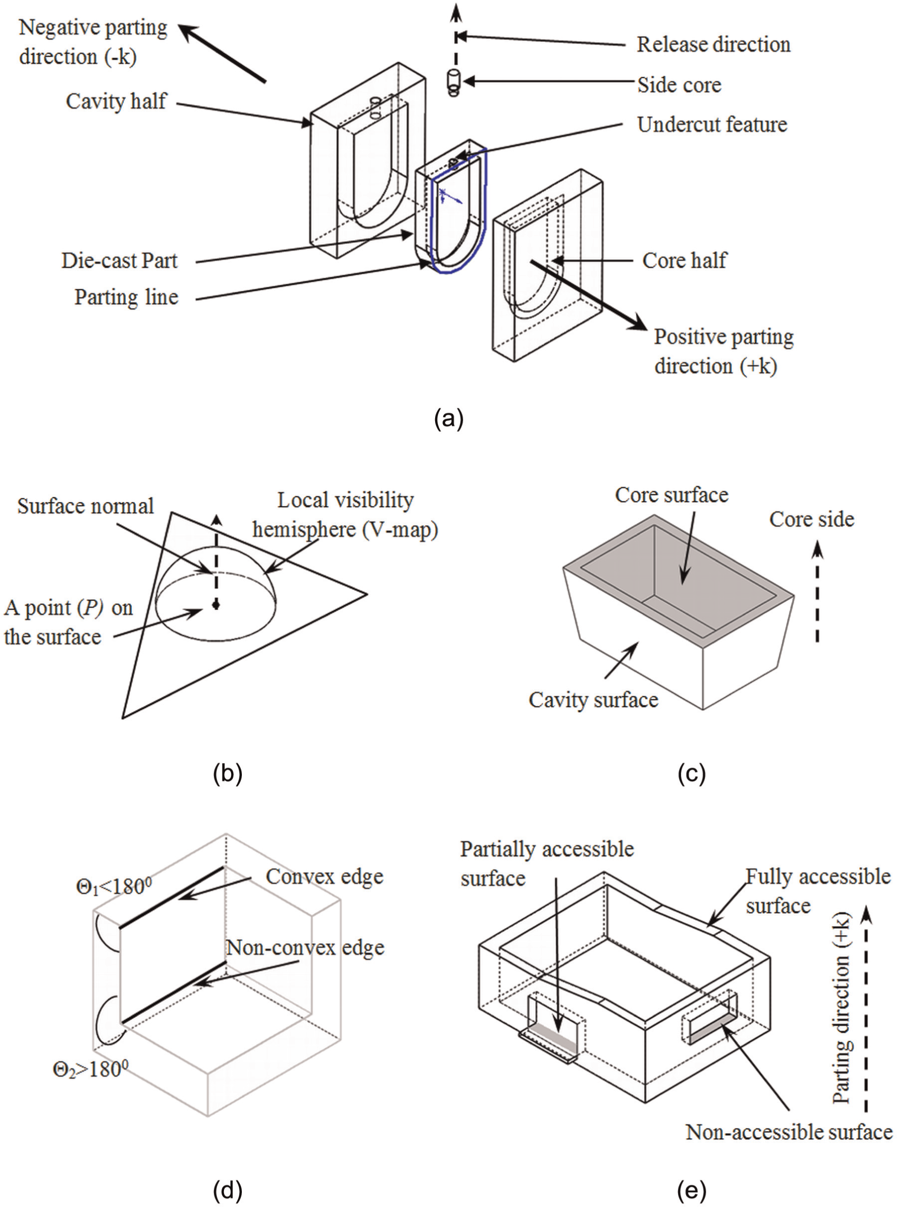
Pictorial representation of the die-casting die terminology: (a) an exploded view of a typical die-casting die, (b) local visibility of a surface, (c) core and cavity surfaces, (d) classification of edges and (e) classification of surfaces.
It has been reported that die design comprises several activities, which require much time affecting lead time and manufacturing cost of a die-casting part. 6 The identification of undercut features, which is one of the critical activities, affects the determination of parting line and core–cavity design. Moreover, the side-core, which is a special tooling for moulding undercut features, is designed after the undercut features are identified. Normally, the identification of undercut features is done manually by the die design expert, and thereafter, the side-core is designed with the help of a computer-aided design (CAD) software. It can therefore be said that undercut feature recognition is a gap in the design-manufacturing integration of the die-casting process. This research work is an effort to bridge this gap, wherein automatic identification of complex undercut features is proposed along with the methodology to divide them into simple undercut features for facilitating side-core design.
Rest of this article is organized as follows. Section ‘Previous research and objectives of this work’ discusses previous research and objectives of this work. Automatic identification of undercut features is discussed in section ‘Automatic identification of undercut features’. Section ‘Classification of undercut features’ deals with classification of undercut features. The division of complex undercut features into simple ones and determination of their release direction is discussed in section ‘Division of complex undercut features into simple undercut features and determination of their release direction’. Section ‘Implementation and results’ deals with the system implementation on example die-casting parts. The conclusions of this work are presented in section ‘Conclusion’. Finally, the limitations and future scope of this research work are presented in section ‘Limitations and future scope’.
Previous research and objectives of this work
Feature identification from the CAD model of a part is domain specific and has attracted researchers from diverse fields of manufacturing. Undercut feature identification is one special domain application of this research area with application in die casting and plastic mould design. Researchers have used different techniques such as visibility maps, spherical maps and graph-based methods for detection of undercut features.
Dhaliwal et al. 7 employed exact accessibility cones of the part surfaces on a faceted CAD model of the part to generate its regions of inaccessibility. The concept of visibility in a given parting direction was used for determination of undercut features in Surti and Reddy 8 and Liu and Ramani, 9 while Chen 10 and Hui and Tan 11 used the concept of block factor for the same. Wong et al., 12 Fu et al. 13 and Lu and Lee 14 used the concepts of grid line and column insertion test, geometric and topological information and three-dimensional (3D) ray detection, respectively, for recognition of undercut features. Yin et al. 15 employed freedom cones and non-directional blocking graphs as reasoning tools for detecting interacting features. Ye et al. 16,17 used graph-based methods to identify both isolated and interacting undercut features. Khardekar et al. 18 employed graphics hardware to detect the undercut features from a die-casting part model. Banerjee and Gupta 19 computed candidate retraction space for facets of an undercut feature in a given parting direction along with determination of a discrete set of feasible retraction spaces. Kumar et al. 20 applied polyhedron face adjacency graph technique to recognize completely and partially visible undercuts based on the angle between the adjacent polyhedron. The concepts of feature recognition and surface de-mouldability and mouldability for identification and classification of undercut features were reported by Madan et al. 21 and Fu, 22 respectively. Madan et al. 23 proposed a methodology for the recognition of intersecting features and further dividing them into separable regions. Huang 24 applied ray-tracing approach to test the visibility of the edges and surfaces. Boolean subtraction operation between the minimal contour solid and the extruded solids formed from visible surfaces is carried out to recognize undercut features. Bidkar and McAdams 25 used 3D binary arrays of 1s and 0s to represent that the solid and the undercut features are the surfaces formed by solid cubes that cannot be accessed in given parting direction. Bassi et al. 26 used part geometry, topology and accessibility to recognize mould features. Finally, the release direction of the mould feature is determined. Kumar et al. 3 and Ran and Fu 27 used the geometric and topological data of the part to generate core, cavity and secondary moulding tools. Sunil and Pande 28 proposed a system to recognize protrusions and depressions for sheet metal components. Tan et al. 29 used a convex hull algorithm for generating parting lines and parting surfaces. The interlocking elements for the given parting direction were also detected.
Research gaps
From the literature review, it is concluded that despite very useful previous work, identification of complex undercut features has not got due attention. The research gaps in the previous research are mentioned below:
Recognition of complex undercut features is not fully attended.
Classification of complex undercut features is not attempted.
Division of the complex undercut feature into simple ones remains unaddressed.
Table 1 presents a summary where the capabilities of the previous work with respect to the issues addressed in this work have been compared.
Summary of comparison of the previous research.
Objectives of this article
This article addresses the research gaps mentioned in the previous section. The objectives of this article are mentioned below:
Identifying complex undercut features of the die-cast part.
Classifying complex undercut features.
Dividing the identified complex undercut features into simple features.
Determining release direction of the simple undercut features.
Problem statement
The undercut feature in a die-cast part is generally a non-convex region (NCR) that cannot be moulded in the selected parting direction. The problem statement has been defined in the following paragraphs.
Problem.
Identify the undercut features of a die-cast part P.
Output requirements.
The complex undercut features to be divided into simple undercut features.
Combine the undercut features with common release direction.
Input requirements.
A B-rep file of the die-cast part.
Positive parting direction of the die-cast part in the direction +k.
Assumptions.
The die-casting part is mouldable.
The parting direction is input to the system by the user.
The complex undercut features have planar surfaces only.
Automatic identification of undercut features
The steps that are involved in automatic identification of undercut features are mentioned in the following sections.
Classification of surfaces of the part
The classification of surfaces of the part model is done on the basis of local visibility of the surfaces. The surfaces of the part model are classified into up, down and neutral surfaces based on the dot product (DP) of parting direction +k and the surface normal ηi (DP = ηi· k). The results of the DP are divided into three groups based on the following relationships:
If DP > 0, the surface is an up surface.
If DP < 0, the surface is a down surface.
If DP = 0, the surface is a neutral surface.
The classification of surfaces is further illustrated in Figure 2.
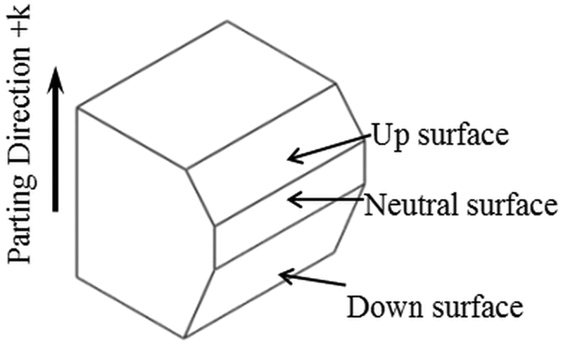
Classification of surfaces of a die-cast part.
Identification of NCRs
NCR is a group of non-convex surfaces (NCSs), which are connected by non-convex edges (NCEs). A NCS contains at least one NCE. Following are the steps to identify NCRs:
Identify all NCEs of the part. An example die-cast part with NCEs is shown in Figure 3(a).
Identify NCSs, which have at least one NCE. NCSs for the example die-cast part are shown in Figure 3(a).
Group the NCSs, which have edge connectivity, to form NCRs. The NCR formed by the NCSs of an example part is shown in Figure 3(b).
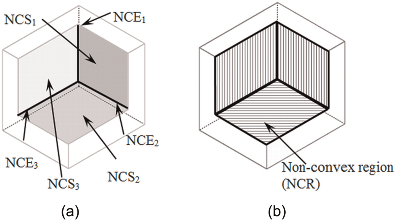
A schematic of a non-convex region: (a) non-convex edges (NCE) and non-convex surfaces (NCS) and (b) non-convex region.
Identification of core, cavity and undercut surfaces
The methodology for identification of core, cavity and undercut surfaces has the following steps.
Determination of accessibility
Accessibility of a NCS is determined by checking the obstruction of a NCS with other surfaces of the same NCR. For this purpose, the algorithm used by Singh and Madan 2 to check the accessibility of the surface in the parting direction has been applied. A NCS is hence divided into three classes: fully accessible, non-accessible and partially accessible. The partially accessible surfaces need to be divided into surface patches to check if they are mouldable with core, cavity or a side-core, which is discussed next.
Classification of partially accessible surfaces
The partially accessible surfaces are first divided into accessible surface patch and non-accessible surface patch as illustrated in Figure 4(a). The classification of partially accessible surface is based on the relative positions of accessible surface patch and non-accessible surface patch of the same partially accessible surface. The partially accessible surface is classified as (1) the surface having accessible surface patch inside the boundary of non-accessible surface patch (Figure 4(a)) and (2) the surface having accessible surface patch outside the boundary of non-accessible surface patch Figure 4(b).
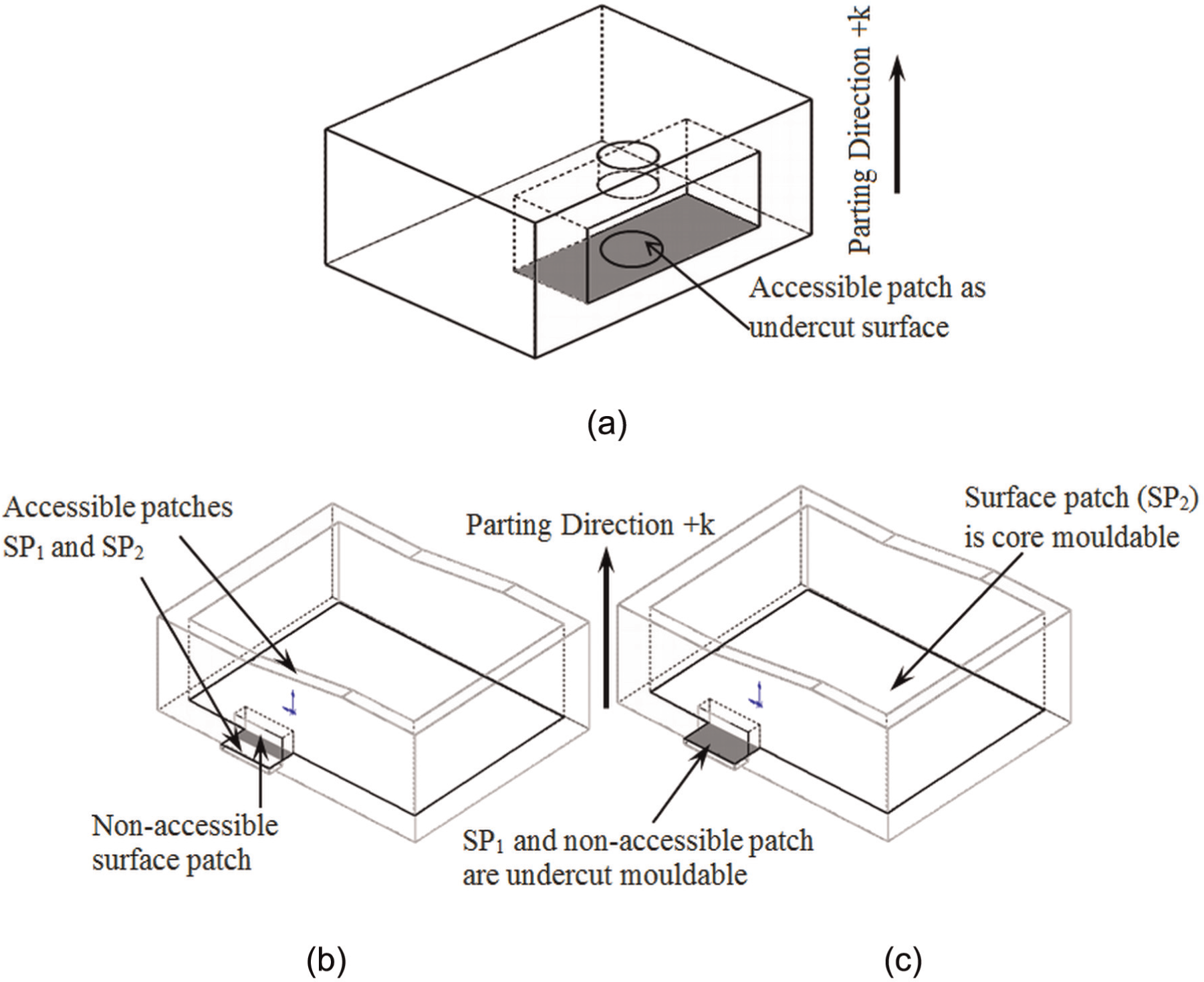
Mouldability of the partially accessible surfaces. (a) Accessible patch inside the boundary of a non-accessible patch, (b) accessible surface patch outside non-accessible surface patch and (c) determining mouldability of the surface patches.
Algorithm for identification of undercut surfaces
In this section, based on the above classification of partially accessible surfaces, the core, cavity and undercut surface patches are identified. The undercut features are then identified using the algorithm presented in Figure 5. The main steps of the algorithm are mentioned below:
Take parting direction of the die-cast part as user input and recognize NCSs of the die-cast part.
Determine the accessibility of the surface in the given parting direction.
If the surface is accessible, it is mouldable by either core or cavity, otherwise the surface is either non-accessible or partially accessible.
If the surface is non-accessible in the parting direction, then it is an undercut surface.
If the surface is partially accessible, then it is divided into accessible and non-accessible surface patches. An example of a partially accessible surface and its division into accessible and non-accessible surface patches is shown in Figure 4(b). The non-accessible patch is an undercut surface.
If the accessible surface patch lies inside the boundary of a non-accessible surface patch, then the patch is an undercut surface (Figure 4(b)).
If the accessible surface patch (like SP1) has convex edges and lies outside the boundary of a non-accessible surface patch, then it is an undercut surface (Figure 4(c)).
If the accessible surface patch (like SP2) has NCEs and lies outside the boundary of the non-accessible surface patch, then it is mouldable by either core or cavity (Figure 4(c)).
The accessibility check for all the NCSs of the part is completed following the procedure mentioned in steps 1–8.
The undercut surfaces having edge connectivity are grouped together to form an undercut feature.
The surfaces accessible in the positive parting direction (+k) are the core mouldable and those accessible in the negative parting direction (−k) are cavity mouldable.
The parting line is generated from the core and cavity surfaces using the algorithm presented by Singh and Madan. 2
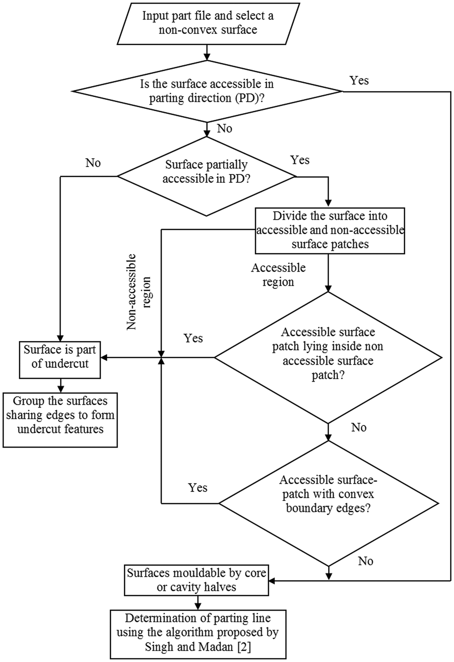
Information flow diagram for identification of undercut features.
Classification of undercut features
Undercut features are broadly classified as simple and complex. Simple undercut features are isolated and have a unique release direction. However, the complex undercut features are formed due to intersection of simple features, each having a different release direction. A complex undercut feature is identified by the presence of either (1) common convex edge(s) between two undercut surfaces or (2) convex edge loop on an undercut surface, the edges of which are shared by other undercut surfaces. In Figure 6, the classification tree for undercut features is presented. The classification of undercut features is explained in the following paragraphs along with the illustrations in Figure 7.
The blind depression (or isolated depression) is simplest of the depression features having convex edge loop at the outer convex surface and a NCE loop at the inner NCS as shown in Figure 7(a). 20
Tapered blind is a blind depression feature having convex edge loop at the outer convex surface and a NCE loop at the inner NCS with varying cross-sectional area over its length as shown in Figure 7(a). This results in bigger area of convex edge loop than that of NCE loop.
Through depression is formed when the depression feature cuts through the material from one side and is seen on the other side as shown in Figure 7(b). Such type of undercut feature is identified by two convex edge loops formed on two outer convex surfaces. 20
Through depression intersecting with mouldable region has one end intersecting with mouldable region. This type of undercut feature is depicted in Figure 7(b), and it is identified by the presence of convex edge loop on a NCS of the mouldable region.
Tapered through is a through depression feature with varying cross-sectional area over its length. One such feature is illustrated in Figure 7(c). Similar to a through depression feature, a tapered through feature is also identified by two convex edge loops, but with different areas.
Through depression intersecting with undercut region is a through depression with inner edge loop intersecting with undercut region. This type of undercut feature is shown in Figure 7(d). In such a type of undercut feature, there is a convex edge loop on a NCS. This NCS has a convex edge at its boundary.
Unbounded undercut feature is the intersection between two blind depression features such that the intersection boundary of the two is not clear as shown in Figure 7(e). This type of undercut feature is identified by the presence of one convex edge, which is common to two NCSs.
Nested blind depression feature is a nested blind depression within a blind depression feature. This type of undercut feature is identified by the presence of a convex edge loop on one of the NCS of the NCR. A nested blind depression may be further classified as mouldable and non-mouldable as is shown in Figure 7(f).
Nested protrusion feature is a protrusion within a depression feature. Such a feature is identified by the presence of a NCE loop on a NCS. The nested protrusion feature may further be classified as mouldable and non-mouldable features as shown in Figure 7(f). 20
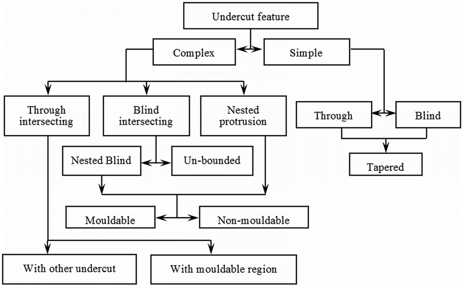
Classification tree of die-casting undercut features.
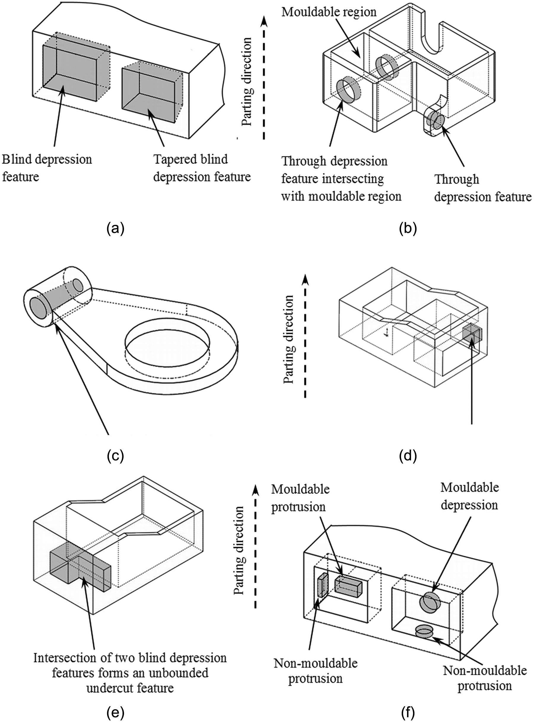
Instances of undercut features: (a) blind undercut features, (b) through undercut features, (c) tapered through depression feature, (d) through depression feature intersecting with the undercut region, (e) unbounded undercut feature and (f) nested depression and protrusion features.
Division of complex undercut features into simple undercut features and determination of their release direction
As defined earlier, a complex undercut feature is formed due to intersection of simple features, each having a different release direction. The complex undercut features therefore need to be divided into simple undercut features, each one of which has its own release direction. In this article, complex undercut features, namely, unbounded, intersecting with other undercut feature and intersecting with mouldable region are considered for division into simple undercut features. The methodology for dividing the complex undercut features, having planar surfaces, into simple features is discussed in the following paragraphs.
Division of unbounded undercut feature
An unbounded undercut feature has only one convex edge common to NCSs of a complex undercut feature. The methodology of division of unbounded undercut is explained in the following steps:
Select the common convex edge between the two undercut surfaces (Figure 8(a)).
Find the shortest NCE sharing the end points of convex edge (Figure 8(a)).
Construct an edge starting from the common point between convex edge and shortest NCE and extend the selected NCE (Figure 8(a)).
Create a surface passing through the convex edge(s) and extensions of NCEs (Figure 8(a)).
Find the intersection of the surface with the surfaces of the undercut feature, which is named as the intersection edge (IE) (Figure 8(b)).
Create a surface patch bounded by the common convex edge(s) (found in step 1), the constructed edge (found in step 3) and the IE (found in step 5) (Figure 8(b)).
This surface patch separates the complex undercut feature into simple undercut features (Figure 8(b)).
The simple undercut features obtained by dividing the unbounded undercut feature are shown in Figure 8(c) and (d).
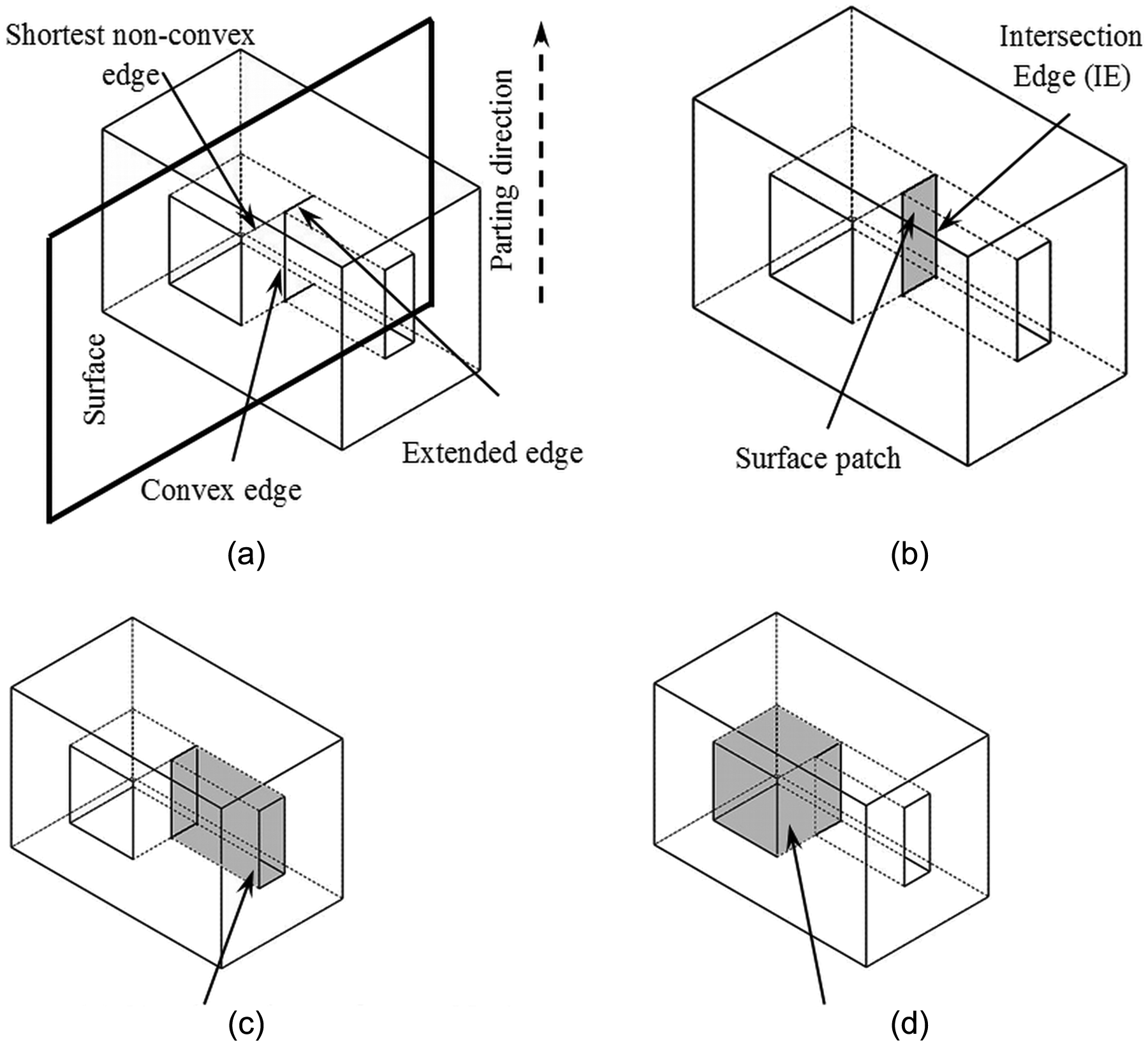
Division of unbounded undercut feature: (a) extension of shortest non-convex edges, (b) creating a surface patch, (c) simple undercut feature No. 1 and (d) simple undercut feature No. 2.
Division of undercut feature intersecting with other undercut feature
The methodology for division of this type of complex undercut features is as follows:
Create a surface patch inside the convex edge loop of a complex undercut feature as shown in Figure 9(a).
Separate the NCSs on both sides of the surface patch created in step 1. This will generate two simple undercut features, as shown in Figure 9(b) and (c).
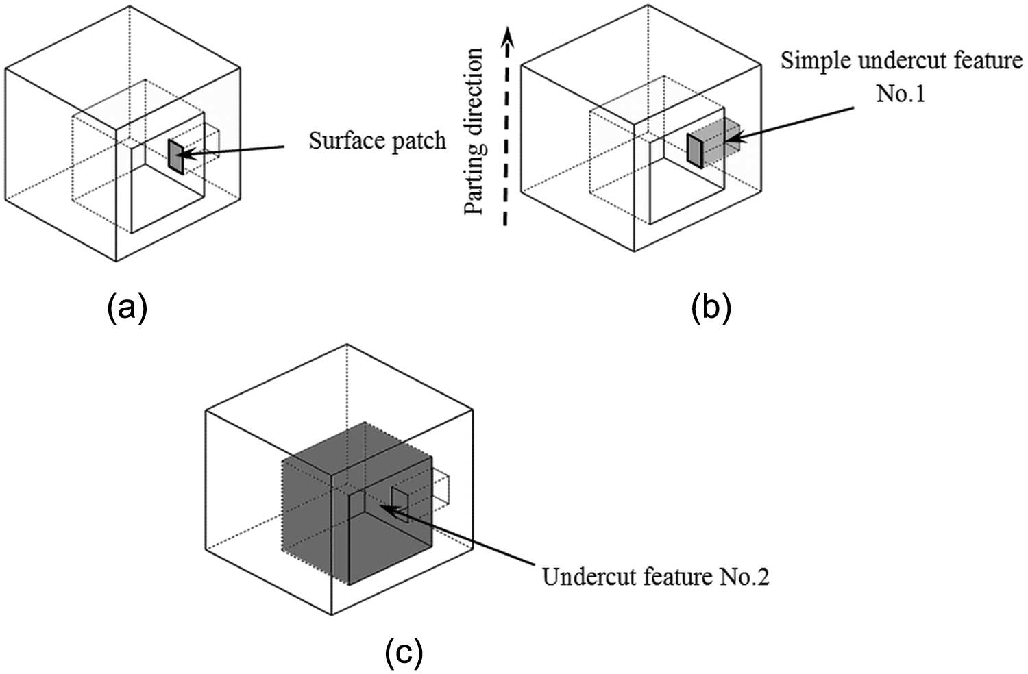
Division of complex intersecting undercut feature: (a) creating a surface patch bounded by the convex edge loop, (b) an instance of division of a complex undercut feature and (c) division of undercut feature intersecting with another undercut feature.
Division of undercut feature intersecting with mouldable region
The implementation of the methodology on an example part is shown in Figure 10 and is explained in the following paragraphs:
Create a surface patch inside the boundary of the convex edge loop of the complex undercut feature (Figure 10(a)).
Separate the NCSs on both sides of the surface patch. This will generate two features, one side-core mouldable and the other one mouldable by core/cavity (Figure 10(b) and (c).
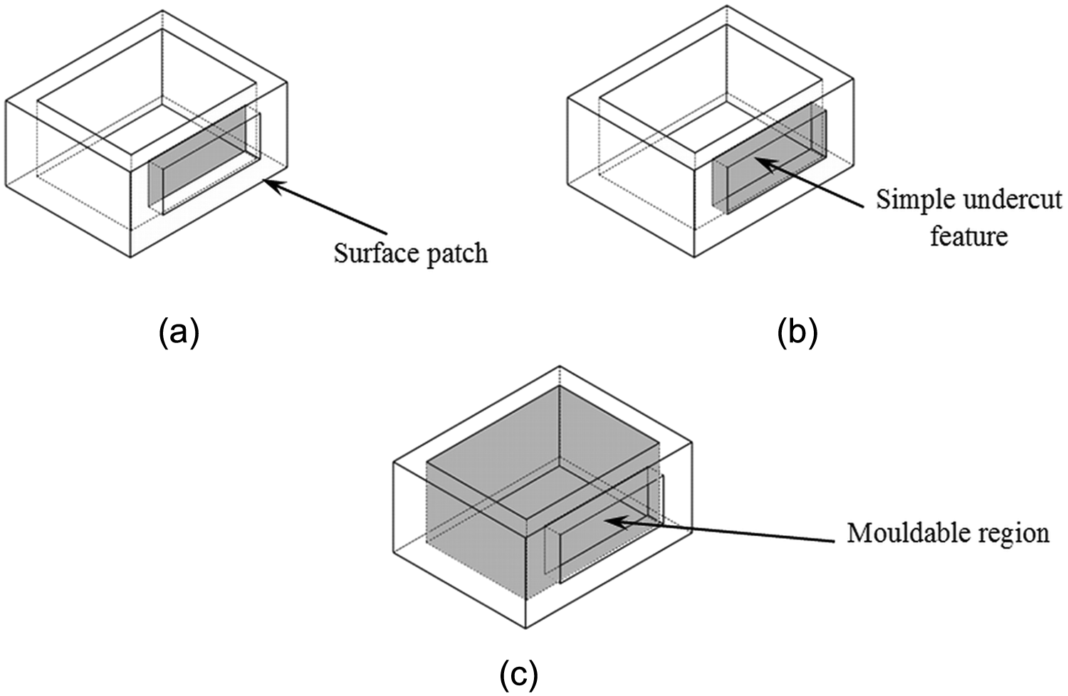
Division of undercut feature and intersecting mouldable region: (a) creating a surface patch bounded by the convex edge loop, (b) identification of simple undercut feature intersecting with mouldable region and (c) identification of mouldable region intersecting with undercut feature.
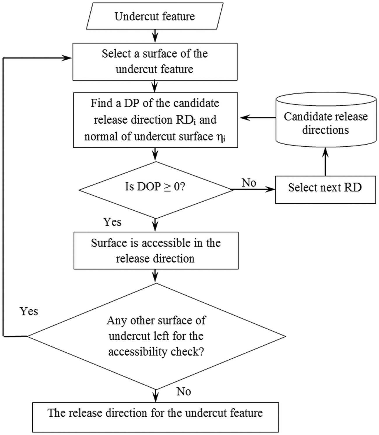
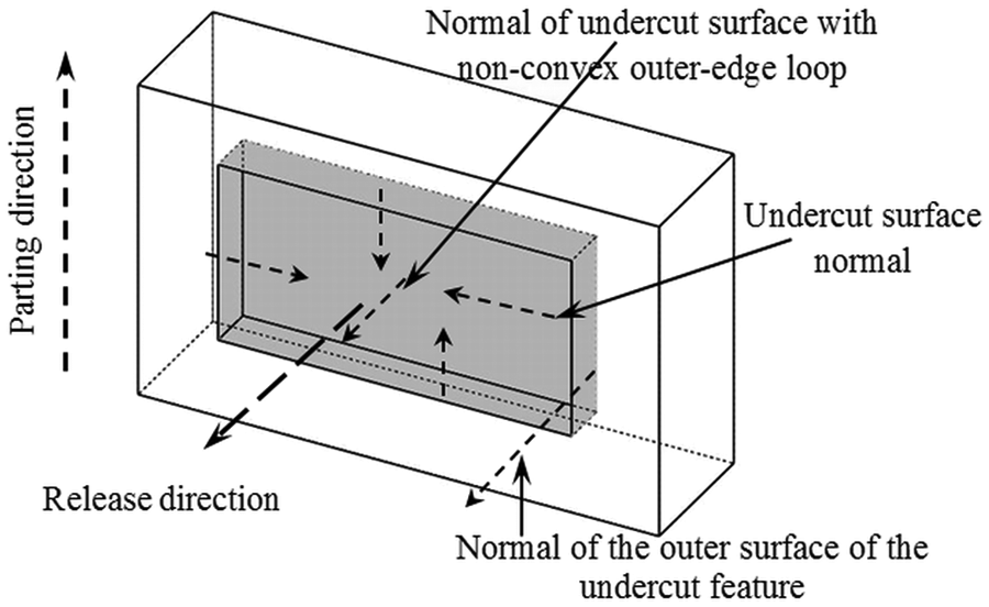
Determination of release direction of side-cores
The release direction of a side-core for a simple undercut is the direction in which all the undercut surfaces and surface patches are accessible, which is found by checking their global visibility in a candidate release direction. A candidate release direction, in which all the surfaces of undercut feature are visible, is selected as the undercut release direction. The following candidate release directions (RDi) are considered:
Normal of the undercut surface bounded by a NCE loop;
Normal of the surface of the part on which undercut feature is formed;
User-defined release directions.
The information flow diagram for determination of release direction is presented in Figure 11 and its description is as follows:
A candidate release direction is selected for a simple undercut feature as mentioned in the previous paragraph.
The accessibility of a surface of the simple undercut feature is checked in the candidate release direction. The accessibility of an undercut surface is determined using the DP of its normal, ηi, with the candidate release direction: RDi (DP = ηi· RDi). If DP ≥ 0, the surface is visible in the candidate release direction.
The undercut release direction is the one in which all the undercut surfaces are accessible. One such instance of an undercut release direction is shown in Figure 12.
After the release directions of the undercut features are determined, the next step is to group those undercut features, which have common release direction. Such a group of undercut features can be used to design a common side-core for the group.
Information flow diagram for determination of release direction of a simple undercut feature.
Determination of release direction.
Implementation and results
The proposed system is implemented on example die-cast parts, the results of which are presented in this section. The results for example part No. 1 are presented in Figure 13. The system identifies and classifies the undercut features, which are shown in Figure 13(a). The undercut features present on the part are of the following types: (1) unbounded undercut feature and (2) undercut feature intersecting with the mouldable region. The complex undercut features are then divided into simple undercut features as shown in Figure 13(b). Finally, the release direction for the undercut features is determined. Figure 13(c) shows the release direction of each of the undercut feature denoted as RD1, RD2, RD3 and RD4.
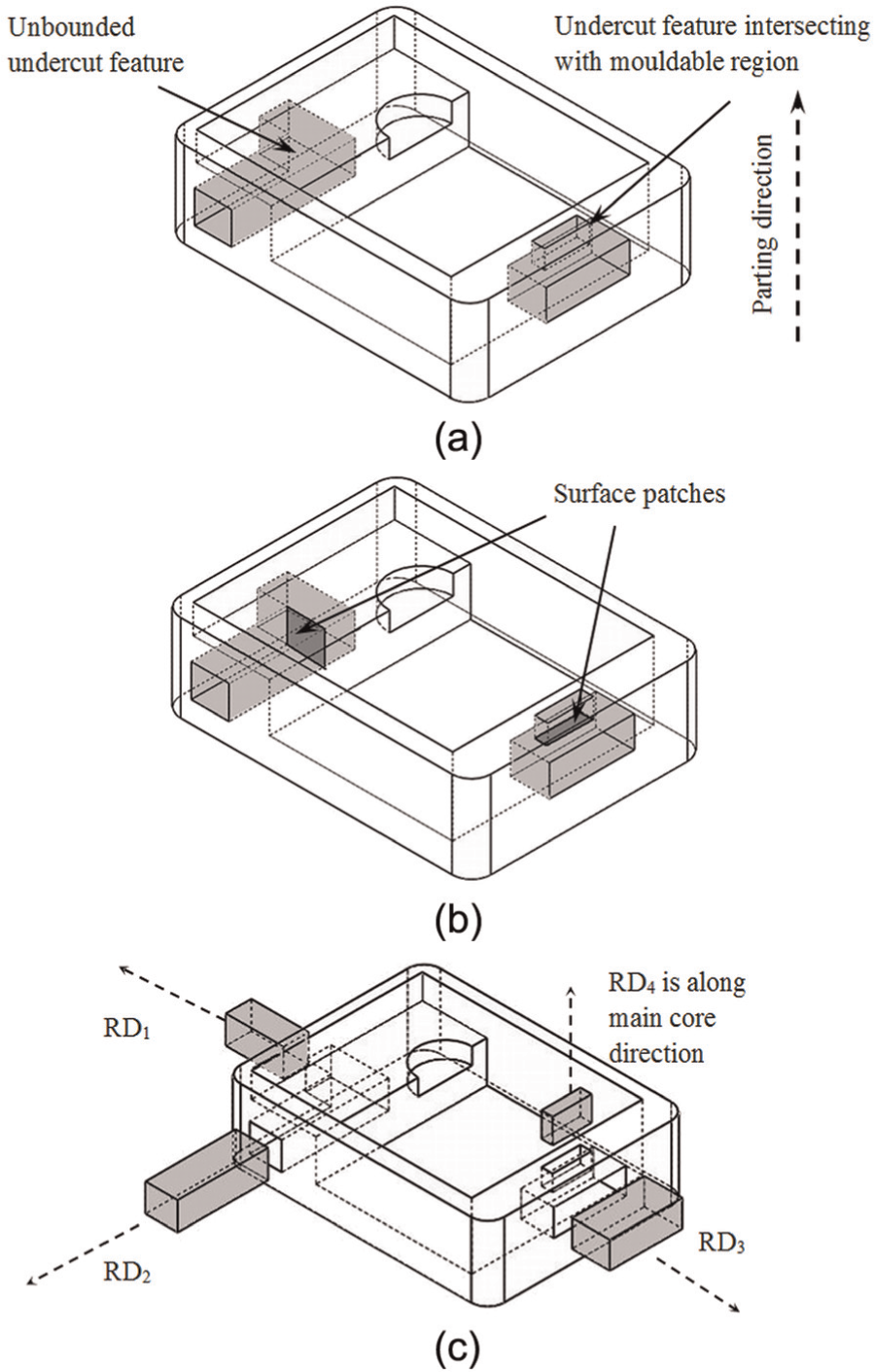
Results for example part No. 1: (a) part model with complex undercut features, (b) division of complex undercut features and (c) side-core with release direction.
Example part No. 2 also has a complex undercut feature, which has two simple undercut features as shown in Figure 14(a). These simple undercut features are intersecting and are divided by creating a surface patch, at the intersection, as depicted in Figure 14(b). Thereafter, the release direction of these simple undercut features is determined. The undercut release directions RD1 and RD2 are shown in Figure 14(c).
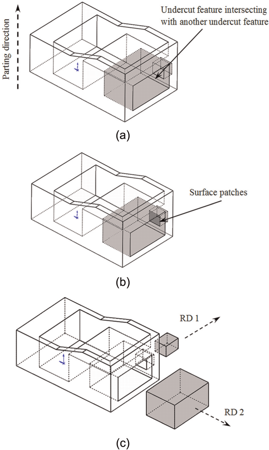
Results for example part No. 2: (a) part model with complex undercut features, (b) division of complex undercut features and (c) side-cores with release direction.
The methodology presented in this work is implemented on complex undercut features that have specific geometric shapes. However, the methodology is general and may be extended to other geometric shapes with slight modifications.
Conclusion
A system for automated recognition of complex undercut features for side-core design of die-cast parts has been developed. The system is used to automatically recognize the complex undercut features of die-cast parts, which do not have a single withdrawal direction. The conclusions drawn from this research are the following:
The recognition of complex undercut features in die-cast parts requires special attention, as they need to be divided into simple undercut features. Each of the simple undercut features has its own withdrawal direction.
The developed system presents a novel method to identify, classify and separate the complex undercut features into simple undercut features and determines their release directions.
Those simple undercut features, which have common withdrawal direction, are grouped. A group of such simple undercut features, identified by the proposed system, can be further used to design their common side-core.
The proposed system is implemented on die-cast parts with complex undercut features having planar surfaces. The results obtained for example die-cast parts are verified with the industry.
This article demonstrates the application of the developed system on selected features. However, the algorithm is generic and can be applied to other features with different shapes. For example, if the number of sides of the undercut intersecting with other undercuts (see Figure 9) is changed, the developed algorithm will still work. For some of the other features, a slight modification in the algorithm will serve the purpose.
A die-casting die design expert spends on an average 30–40 min to identify, classify and separate the complex undercut features into simple ones along with determination of release direction. However, with the help of the developed system, it takes only 1–2 min for the same activities.
The system would facilitate automation of the die design process by (a) reducing the lead time for die design, (b) generating information for the downstream activities such as core and cavity designs and side-core design and (c) realizing design-manufacturing integration for the die-casting die design process.
Limitations and future scope
The present system for identification of complex undercut features for side-core design of die-casting part has some limitations. In the following paragraphs, the limitations and future scope of work are presented.
The proposed system can identify die-cast parts and complex undercut features with planar surfaces only. The future work may involve parts having non-planar surfaces. With the identification of complex undercut feature and their division into simple undercut features, the work presented in this article can be extended to automated design of side-cores.
Footnotes
Acknowledgements
This article is a revised and extended version of the article entitled ‘Automated identification of complex undercut features for side-core design for die-casting parts’, presented at the 4th International and 25th All India Manufacturing Technology, Design and Research (AIMTDR 2012) conference held at Jadavpur University, Kolkata, during 14–16 December 2012. The authors are thankful to the conference organizers and reviewers for their suggestions and invitation for submitting revised and extended version of the article to the journal.
Declaration of conflicting interests
The authors declare that there is no conflict of interest.
Funding
This research received no specific grant from any funding agency in the public, commercial or not-for-profit sectors.