
Abstract
The microstructure and mechanical properties of the deformed materials obtained by equal channel angular pressing are strongly dependent on the amount of induced strain and strain homogeneity developed during history of the process. In this work, a new route for equal channel angular pressing process was proposed and investigated by finite element method. This new route consists of a combination of Routes BC and C by alternating rotations through 90° and 180° after every pass. In other words, the billet is rotated 180° after the first and the third passes around its longitudinal axis like Route C and after the second pass is rotated 90° around its longitudinal axis like Route BC. In comparison with other routes, it was shown that the strain homogeneity achieved by this proposed route is better than other conventional routes. The finite element method results for Route BC were validated by available experimental data, which can support finite element method results for the new proposed route.
Introduction
Developments in materials can be achieved by either introducing new materials, which is often problematic and/or expensive, or improving existing materials. Recently, the latter method has been extensively used to improve mechanical and processing properties of metals by reducing their grain size.1,2 In the last few years, equal channel angular extrusion (ECAE) or equal channel angular pressing (ECAP), developed and patented in Russia by Segal in 1977,1,2 has become a very popular tool for studying the evolution of microstructure and properties under severe plastic deformation (SPD). The process is the extrusion of a well-lubricated billet through a die. The die used for ECAP, as shown in Figure 1, consists of two channels of equal cross-sectional area intersecting at an angle of ‘
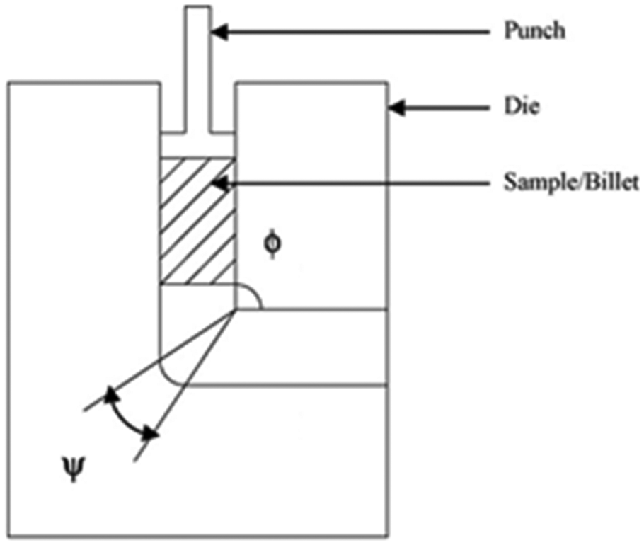
Schematic of ECAP.
A sample (or) billet is inserted into the entry channel and is extruded into the exit channel by a punch. During the deformation, the equivalent plastic strain (effective strain) ‘
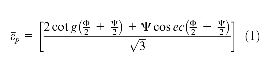
In addition to the induced strain, the material is also influenced by strain hardening of the material and friction between the die and the sample. The strain induced during the deformation influences the microstructure and mechanical properties of the deformed materials.
The billet is then released from the die, rotated by a certain angle about its axis and the operation is repeated. After several such cycles, one can obtain a large deformation and a fine grain structure.
According to Lowe and Valiev, 4 in ECAP process, deformation is localized in the small area around the channels’ meeting line, and as a result, a large uniform simple shear strain is imposed on the billet. It is also believed that the stress characteristics are uniform in the cross section of the billet and that this uniformity of the stress–strain distribution ensures the uniformity of microstructure and mechanical properties in ECAP-processed billet.4,5 However, some experimental data such as the fracture of the extruded billet, which is initiated at the inner surface of the sample, have caused doubts about uniformity of stress–strain distribution. 5 This non-uniformity has been proved recently by finite element simulations.6–8
ECAP method has undergone several constructive changes or modifications since its origin, by focusing on the reduction in contact friction and on the increase in the intensity of deformation during one pass. Design changes were aimed at change in the angle between the channels, the movement of each ECAP die wall and multiple crank of channel within a single ECAP die. Affecting parameters such as shape of the tools and friction can be implemented and investigated using numerical simulations in various software products. 9
During the ECAP, direction and number of passes through the channels are very important for microstructure refinement. In Furukawa et al. 10 and Valiev et al., 11 the following routes of billets were considered: orientation of a billet is not changed at each pass (Route A); after each pass, a billet is rotated around its longitudinal axis by 90° in the same direction (Route BC) or inverse direction (Route BA); and after each pass, a billet is rotated around its longitudinal axis by 180° (Route C). The orientations at the start of the second extrusion for three routes of A, B and C are shown in Figure 2.
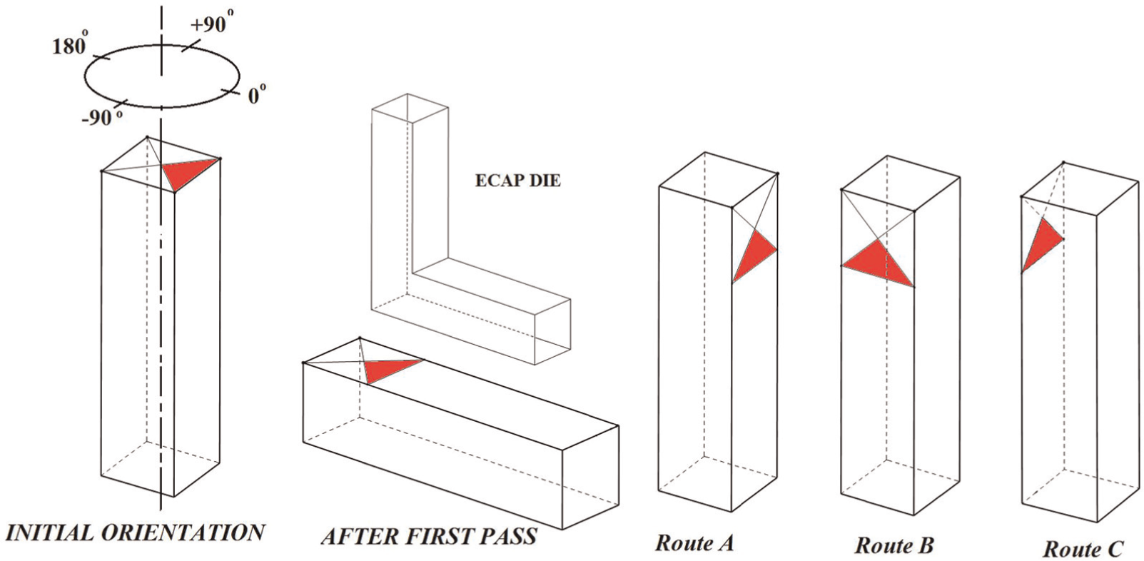
Orientation at the start of second extrusion.
Although the differences of these routes on microstructure of ECAP-processed materials were also analysed by many researchers by both theoretical and experimental methods, the effects of different pressing routes on the deformation homogeneity of the resulted materials were seldom considered. 12 The route that is optimal for achieving ultra-fine grained (UFG) material with more homogeneous microstructure is still under investigation.
In this article, a three-dimensional (3D) finite element method (FEM) was performed to study the deformation distribution of billets after multi-passes by using common pressing routes and a new proposed route. It was shown that the strain homogeneity achieved by the proposed route is better than the other conventional methods mentioned in the literature.
Introduction of a new route for ECAP process
The new proposed route consists of a combination of Routes BC and C by alternating rotations of 90° and 180° after every pass. In other words, the new route includes extruding a billet of material along the first axis in a first orientation through an ECAP die. Then, similar to conventional Route C, the billet is rotated 180° around its longitudinal axis and is extruded. Subsequently, similar to conventional Route B, the billet is rotated 90° around its longitudinal axis and then is extruded. Finally, the billet is rotated 180° like pass 2 and extruded. Figures 3–6 illustrate billet orientations during multiple passes of the proposed route.
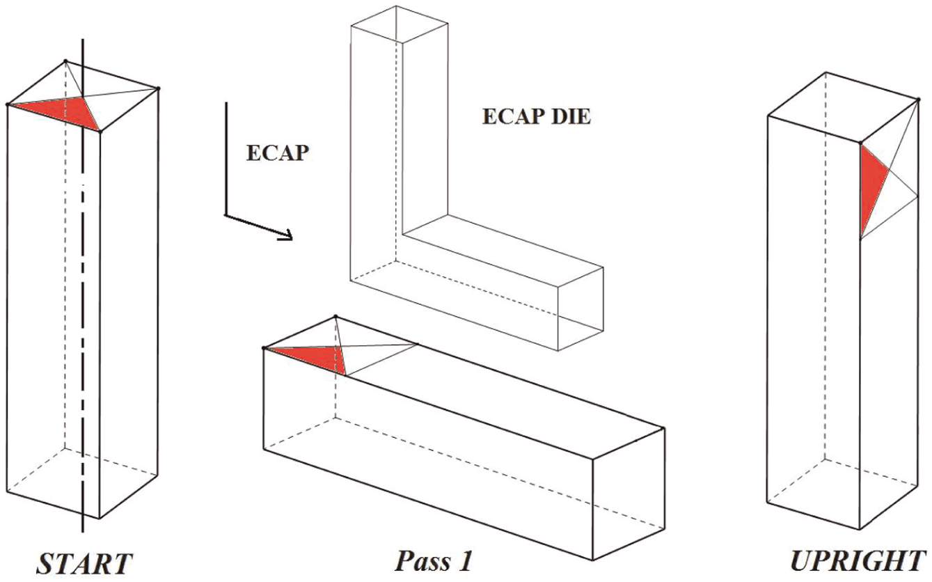
The first pass of the ECAP process.
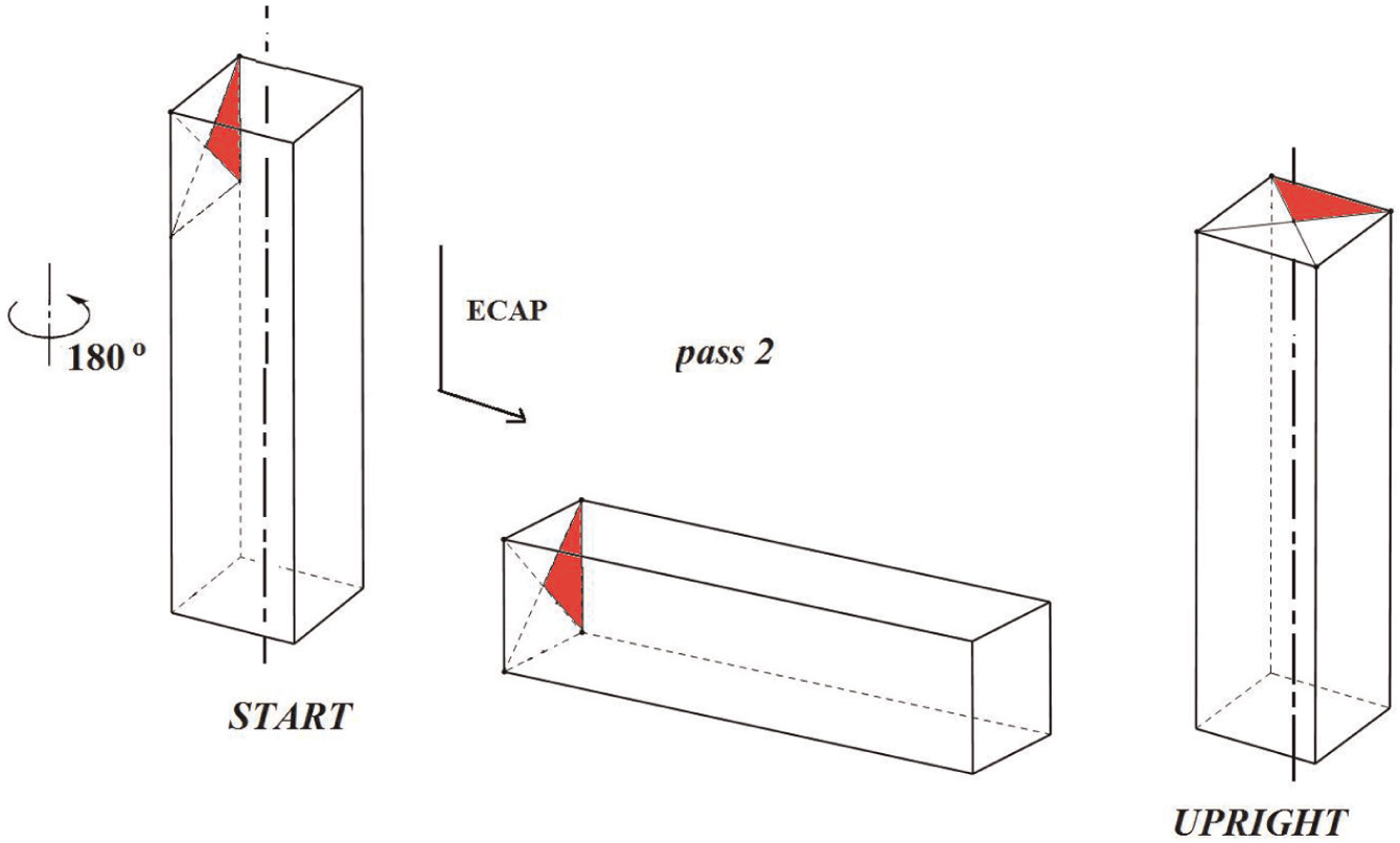
The orientation of the billet after the first pass (180° rotation).
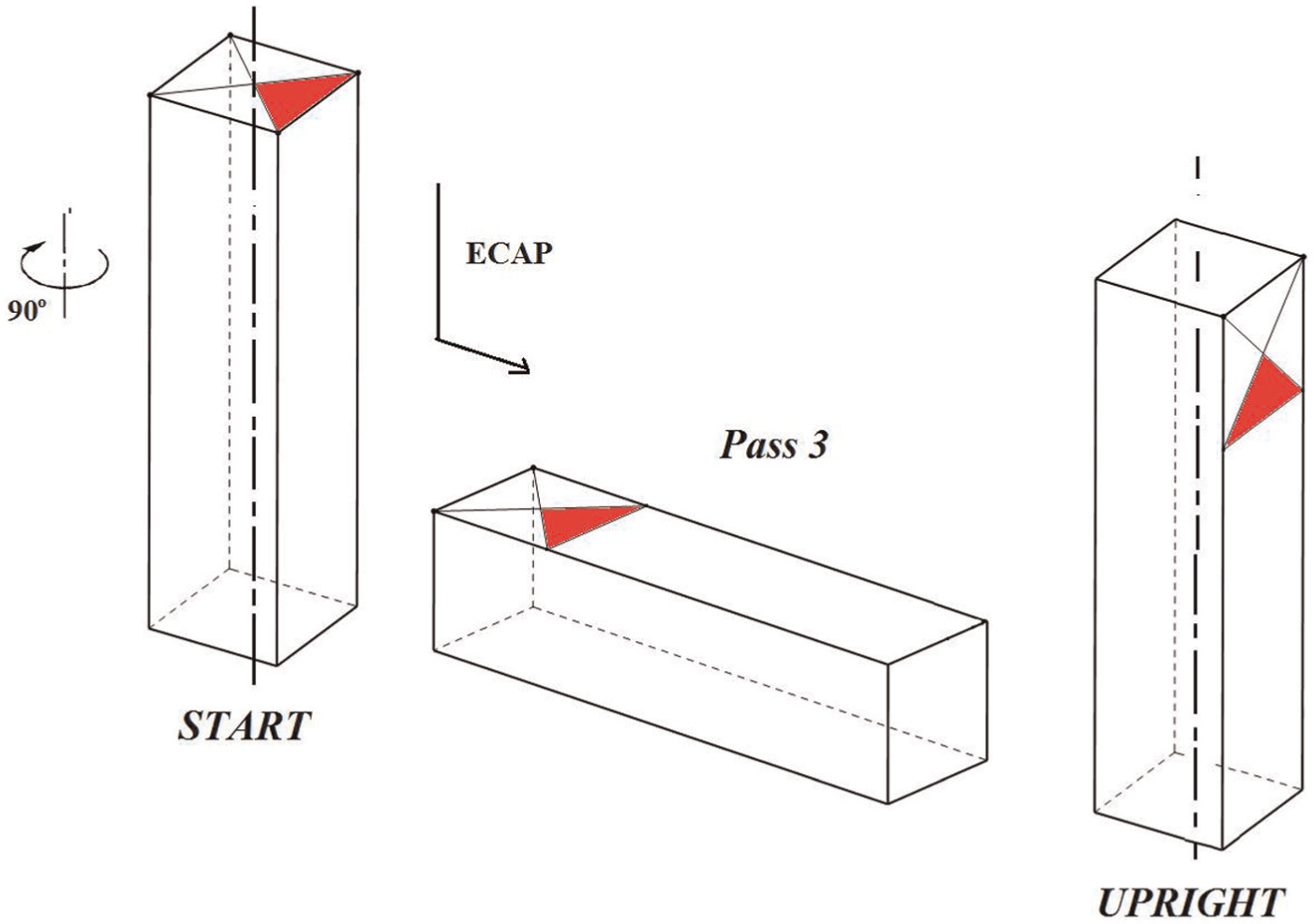
The orientation of the billet after the second pass (90° rotation).
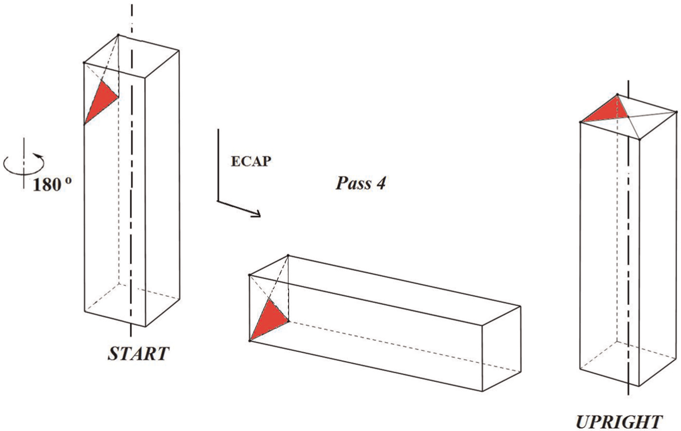
The orientation of the billet after the third pass (180° rotation).
Finite element modelling of multi-pass pressing of conventional ECAP routes
FEM modelling
The commercial FEM program ABAQUS/Explicit was used to simulate the elastic/plastic flow of the material in three routes B, C and the proposed route. Route A was omitted from our investigation since the previous studies have shown that it is not very efficient. 13
According to some previous studies,14,15 for achieving UFG material, the raw material must be pressed at least four to eight times. Due to the complexity of deformation procedure during multi-pass pressing of ECAP, it is impractical to truly analyse the distribution of plastic deformation of the billet by two-dimensional (2D) FEM. So in this article, 3D finite element simulations were employed to study the deformation distribution of billets after multi-passes and using different routes.
Generally, coefficient of friction for metals operating under the good lubrication conditions is between 0.05 and 0.1. 16 A range of 0.03–0.08 was used by Altan et al. 17 for cold extrusion of aluminium under lubricated condition. Besides, it was found that if the friction between the billet and ECAP channel is too high, a few elements in local region are severely distorted, which would lead to the simulation interruptions. Therefore, Coulomb’s law with a friction coefficient of 0.05 was assumed.
For simplicity, the dies were considered to be rigid. A square section billet with initial dimensions of 15 mm × 15 mm × 70 mm is considered. The rigid ECAP die has a corner angle of Φ = 90° and an outer corner angle of ψ = 22°, and both the inlet and outlet channels have the same size as the billet.
The workpiece dimensions and the ECAP die geometry are shown in Figure 7.
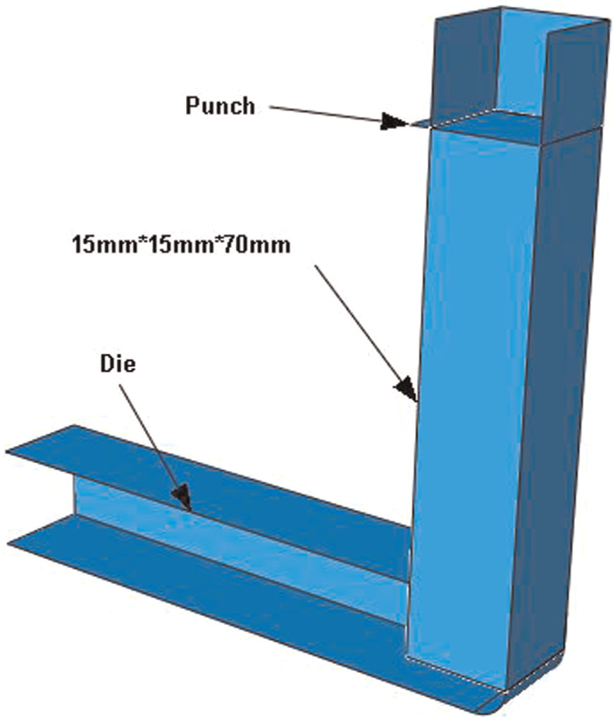
Workpiece dimensions and the ECAP die geometry.
The workpiece was modelled with 48,884 nodes and 44,100 elements using eight-node linear brick elements with reduced integration points and hourglass control (C3D8R). The billet was assumed to be commercial purity copper with Young’s modulus of 69 GPa, Poisson’s ratio of 0.34 and yield stress of 98 MPa. The plastic deformation behaviour of the material is assumed to follow the relationship
For simulation of deformation in various ECAP routes, the required channels for each route were successively considered in each model in correspondence with the appropriate rotations of each route. The FEM models of two conventional Routes BC and C are shown in Figure 8.
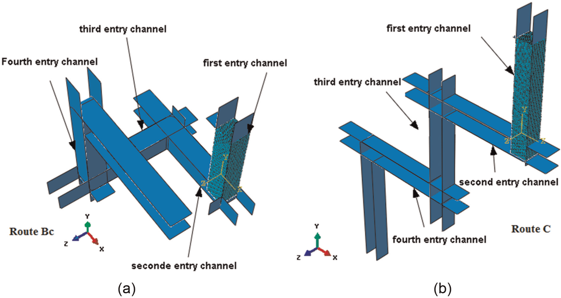
FEM model of (a) Route BC and (b) Route C.
The contact between the surface of the rigid die and the specimen is modelled by surface-to-surface contacts with finite sliding between the surfaces. The dies are fixed and the process is performed in four steps such that in each step only one punch moves.
FEM results
Figure 9 illustrates the final distributions of the equivalent plastic strains of deformed billets by Routes BC and C.
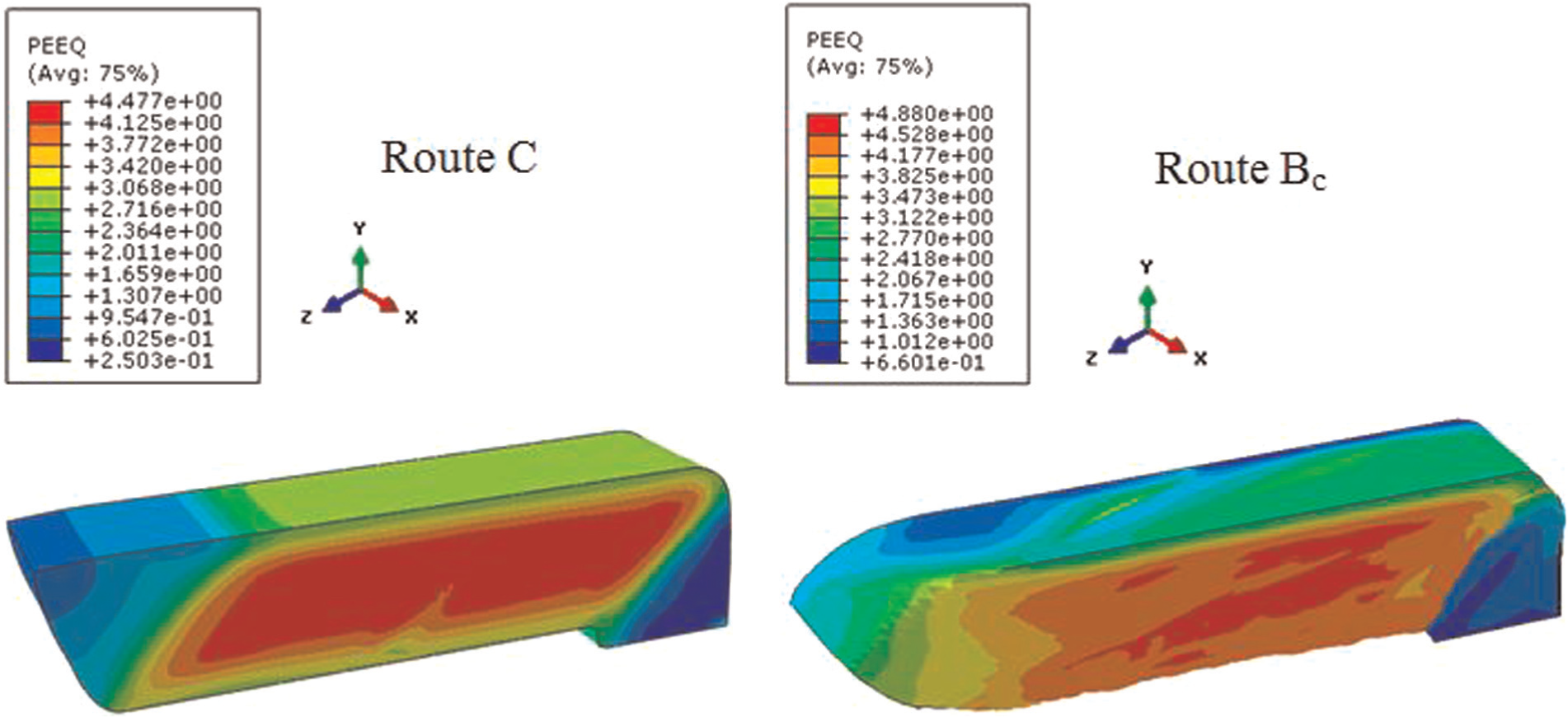
Equivalent plastic strain contours of deformed billets obtained by Routes C and BC.
The contours of the equivalent strains in the middle cross sections of the billets for both Routes BC and C are shown in Figure 10.
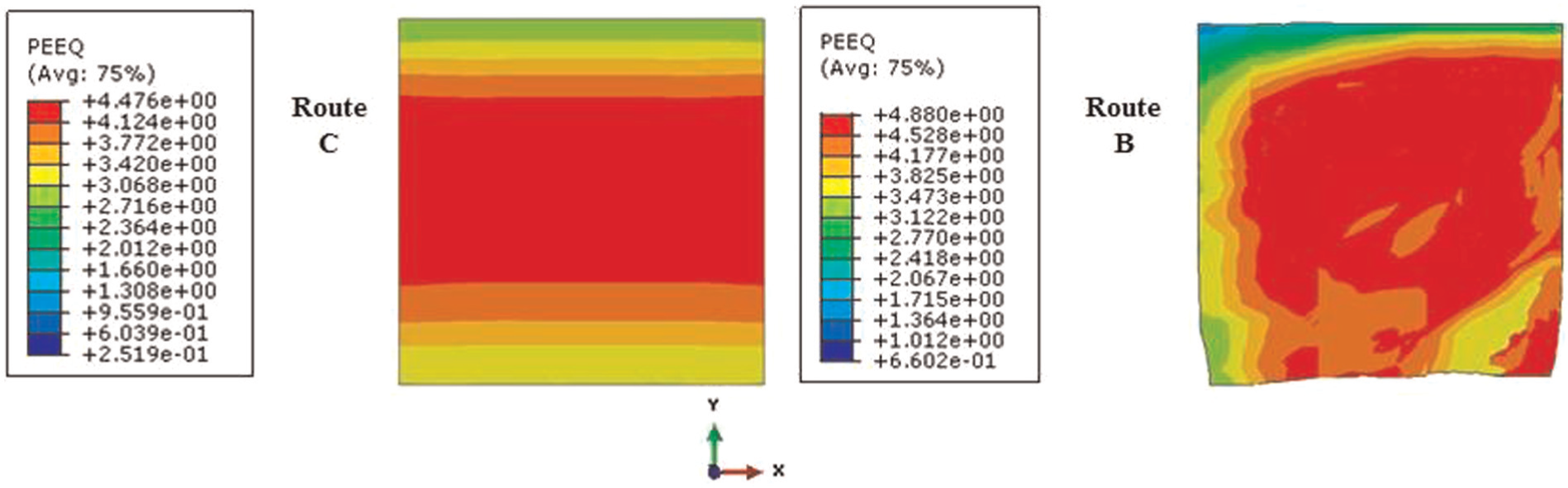
The contours of the equivalent strains in the middle cross sections of the billets (BC and C).
Comparison of FEM results with experimental observations
Comparisons were made for two aspects between the FEM and experimental results. First aspect is the strain homogeneity, while the second aspect is the effect of the
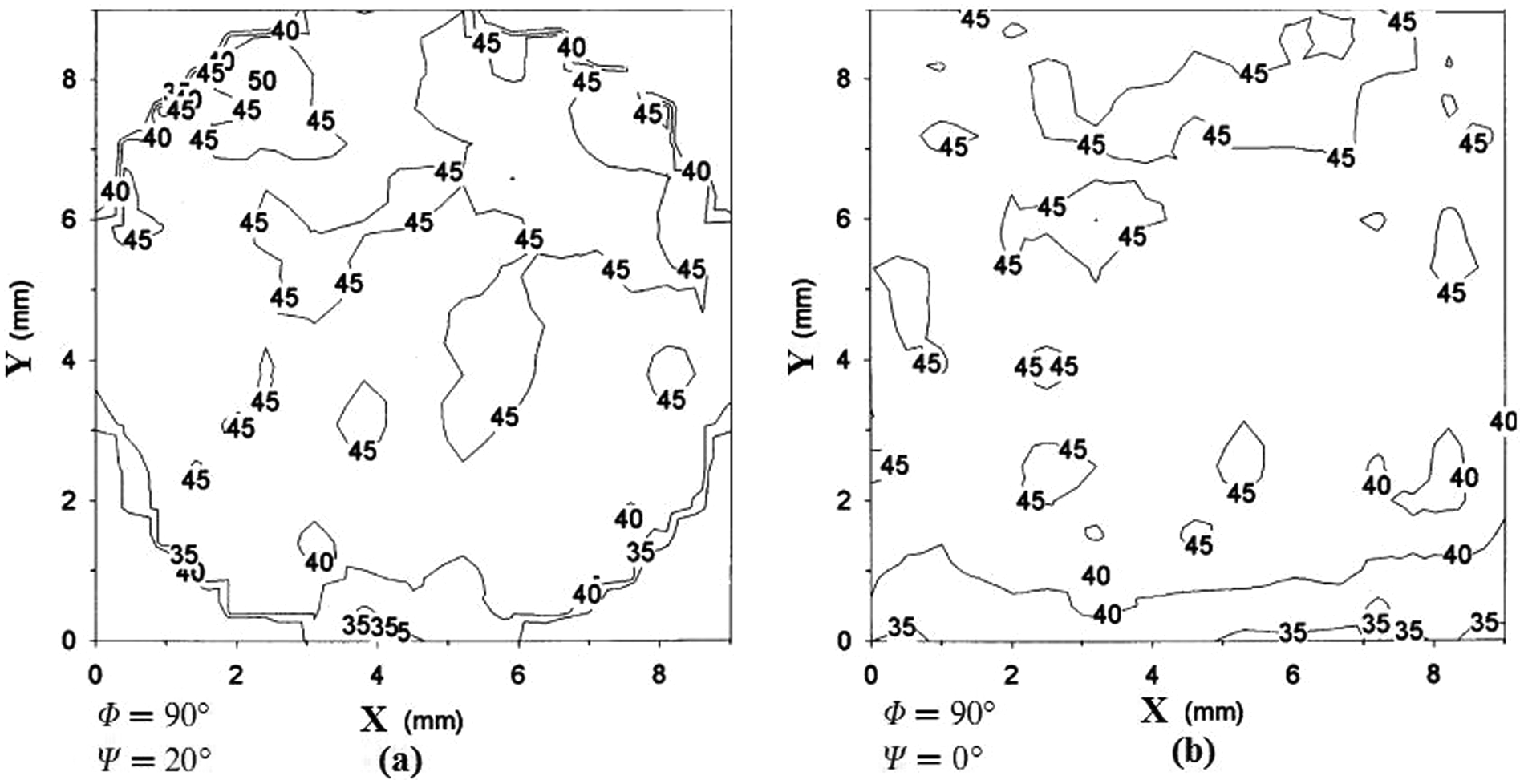
Contour maps showing the values of the micro-hardness recorded on the z-plane of samples of pure Al pressed through four passes using Route BC of an ECAP die with
Careful inspection of Figure 11 shows that both samples exhibit regions of inhomogeneity, which are different from each other, that is, the angle of
Since the geometrical parameters of the mentioned experimental test and frictional regime are the same as our FEM modelling, the experimental results can be compared with the FEM results obtained in section ‘FEM modelling’ for Route BC. By comparing Figures 10 and 11(a) for Route BC, it can be seen that there is a good agreement between the presented FEM results and experimental results. This agreement validates our FEM model and supports other models for various routes, especially the new proposed route, which is investigated in the next section.
Finite element modelling of the proposed ECAP route
For simulation of deformation in the new proposed route, the required channels for successive passes were considered in one model in correspondence with the appropriate rotations of the billet. The FEM model of the proposed route is shown in Figure 12.
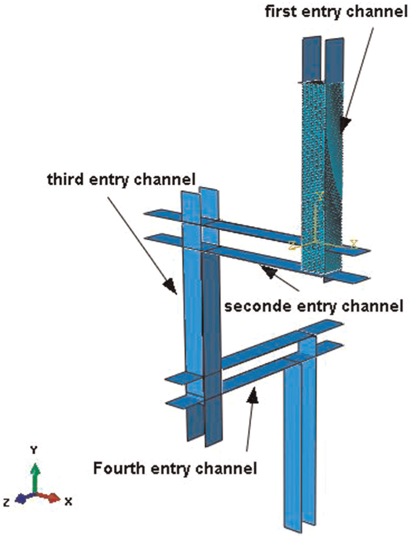
FEM model of the proposed route.
All other settings are the same as the conventional routes of the section ‘Finite element modelling of multi-pass pressing of conventional ECAP routes’. As it can be seen, the billet is rotated 180° after the first and the third passes and 90° after the second pass.
Distributions of the equivalent plastic strain of the deformed billet by the proposed route and the contour of the equivalent strain in the middle cross section of the billet are shown in Figure 13.
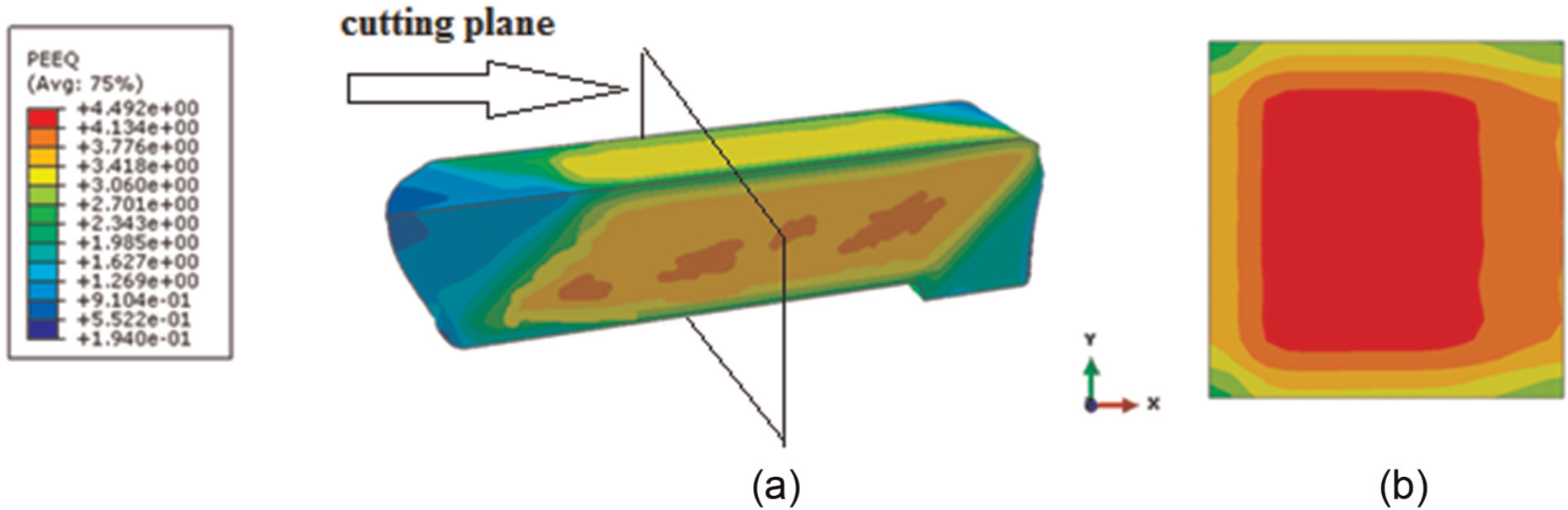
(a) Equivalent plastic strain contours of deformed billet obtained by the proposed route and (b) the contours of the equivalent strains in the middle cross sections of the billet.
Results and discussion
Finite element analyses were carried out to obtain deformation distributions of a billet during four passes. As it can be seen in Figures 9 and 13, the final equivalent plastic strains are different for various routes. However, what is important is the homogeneity of plastic strains inside the part.
According to the literature,12,20,21 inhomogeneity is expressed by an index (C), which is defined as follows
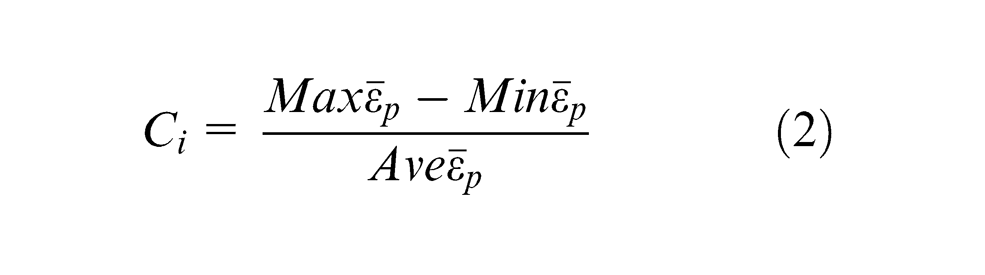
where
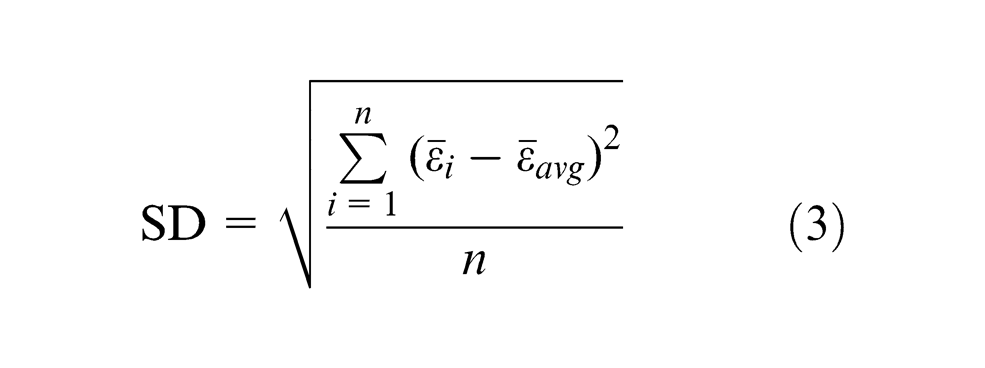
where
Inhomogeneities of various investigated routes in this study are compared by the two above-mentioned criteria, that is, Ci and SD. The strain distributions along the central vertical line of the above-mentioned cross sections (in Figures 10 and 13) are shown in Figure 14.
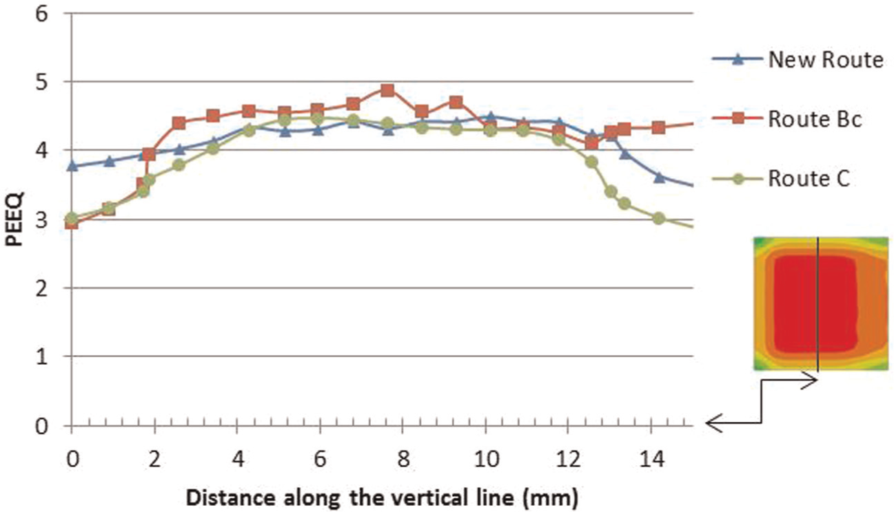
The strain distribution across central vertical line of the cross section of the billet for three routes.
Figure 15 shows the SD and Ci values for three routes of BC, C and the proposed route across the middle cross section of the billet. Number of points in the middle cross section of the billet (n) is 484.
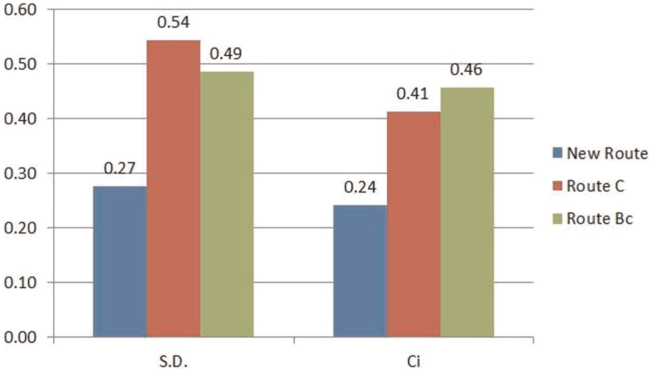
The SD and Ci values for different routes.
As indicated in Figure 15, the SD value of the proposed route is the least among other routes. It means that the proposed route produces the most uniform strain distribution in the cross section of the billet or in other words yields more homogeneous grain sizes. Route BC is ranked the second and Route C is the third in producing homogeneous grain sizes.
Another point observed from Figure 15 is that the Ci value for the Route BC is more than Route C. The authors believe that Ci index is not as good as SD index to show strain inhomogeneity because it does not take into account distribution of strains and it only considers the difference between two extremum values of strains.
Our simulation was validated by the experimental work done by Xu et al. 19 on Route BC. Hence, this validation can be extended to other routes such as the proposed route.
It should be pointed out that although the 3D FEM results show the proposed route is more favourable for producing UFG materials than other conventional routes, and our simulation was supported by the experimental work on Route BC, it should be verified by further experimental results, which is under further investigations and will be addressed in our future works.
Conclusion
Finite element analyses (3D) were carried out for three routes of C, BC and a new proposed route in ECAE with 90° channel angle by ABAQUS/Explicit. Samples were subjected to four passes of ECAP processing at room temperature. Influence of various routes on deformation behaviour and strain homogeneity during ECAP was studied.
Study of the effective strain distribution in the middle cross sections of the billets in x–y plane was conducted. Results show that the strain distribution calculated in the cross section of the billets after four ECAP passes is inhomogeneous for all routes. After four passes, strain homogeneity of the billet processed by using the proposed route is better than other conventional routes. This indicates that the proposed route is more favourable for achieving UFG material with homogeneous microstructure after N passes (N is times of 4). Our simulation was validated by available experimental results of Route BC in the literature. Nevertheless, further experiments are needed to check our deductions. Besides, it is found that the inhomogeneity index (Ci) is not a suitable parameter to quantify the strain dispersal homogeneity. It was shown that SD is a better factor for quantifying the strain distribution uniformity of ECAPed materials.
Footnotes
Appendix 1
Declaration of conflicting interests
The authors declare that there is no conflict of interest.
Funding
This research received no specific grant from any funding agency in the public, commercial or not-for-profit sectors.