
Abstract
Damping of machining vibrations in thin-wall structures is an important area of research due to the ever-increasing use of lightweight structures such as jet engine casings. Published literature has focussed on passive/active damping solutions for open geometry structure (e.g. cantilever thin wall), whereas more challenging situations such as closed geometry structures (e.g. thin wall ring-type casings) were not taken into consideration. In this study, a passive damping solution in the form of tuned viscoelastic dampers is studied to minimise the vibration of thin wall casings while focussing on the change in coupled interaction between tool and workpiece due to added tuned dampers. Finite element simulation was carried out to evaluate the effectiveness of tuned dampers in single impact excitation, and this was further validated experimentally through modal impact testing. A reduction in root mean square value, with tuned dampers, of about 2.5 and 4 times is noted at higher and lower depths of cut, respectively, indicating a moderate dependency on depth of cut. A change in coupled interaction of workpiece with tool’s torsional mode (in undamped state) to that of tool’s bending mode (with tuned dampers) was also noted. Variation in machined wall thickness of the order of 6 µm is noted due to the change in coupled interaction from torsional mode to bending mode of tool.
Keywords
Introduction
The low inherent stiffness of thin wall structures can present significant machining challenges. Common problems that can occur during machining of such structures are static deflections of the workpiece and chatter. While static deflection of the workpiece may contribute towards out-of-tolerance geometries, chatter can produce geometrical inaccuracies, reduced surface finish, excessive tool wear and damage to spindle bearings. Researchers have addressed this problem from two different perspectives – choosing stable (chatter-free) machining parameters and proposing fixturing solutions. A machining system consists of machine tool–workpiece–fixture chain. Calculation of stable machining parameters, usually done by considering regenerative chatter, must take into account one or more of the weak links of this system. The stability lobe algorithms, available through commercially available software such as CUTPRO® and METALMAX®, are currently being used mostly for machines, tools and fixtures and in general are utilised for simple workpiece geometries. Workpiece vibration when machining complex components could be more practically addressed through fixturing solutions. This is mainly due to the complexity involved in obtaining workpiece frequency responses and also due to the fact that it changes with removal of material during machining. Hence, the way to suppress vibration in complex thin wall casings is through appropriate fixture designs. Moreover, the research in suppressing vibration through fixturing solutions was not only driven by the need to overcome the complexity of the component’s geometry, but also, indirectly, by the use of difficult-to-machine workpiece materials so commonly employed in high value-added products such as gas turbine engines. In these situations, due to process damping effects, the stability lobe algorithms are not particularly useful at the low cutting speeds at which these materials are machined.
Typical fixturing solutions researched for improving thin wall machining stability are either standard mechanical fixtures or damping solutions. Research has been carried out in both passive and active damping treatments with a view to suppress vibrations during machining. However, these solutions have sought to dampen vibrations arising from components in machine tool system. Tarng et al. 1 mounted a piezoelectric inertia actuator on the insert holder in turning operation to suppress chatter, and they reported six times improvement in chatter stability. Moradi et al. 2 designed a tuneable vibration absorber for boring bar where they showed that improvement in stability is more when absorber was tuned for higher modes. Yang et al. 3 studied optimisation of multiple tuned mass dampers (TMDs), mounted on tool post, to suppress chatter in turning operation. They reported that multiple TMDs need more accurate tuning to stiffness and frequency, and the damping and stiffness values of TMDs are optimised through numerical method. In addition to these passive and active damping systems, Weinert and Kersting 4 proposed an adaptive passive (adaptronic) damping of chatter vibrations using magnetorheological fluid. The acceleration sensors detect the onset of chatter and alter the strength of the magnetic field passing through the fluid, thereby varying the viscosity of fluid and hence providing the damping to the vibrations.
In a thin wall structure machining, however, damping of workpiece is of major importance; more so in milling of thin walls where the damper cannot be mounted on rotating tool. Only a few researchers have investigated solutions to dampen vibrations arising from the workpiece. Sims et al. 5 reported mitigation of workpiece chatter during milling using granular particle dampers to provide energy dissipation through friction. Using this technique, the depth of cut was able to exceed the previous limit by an order of magnitude. Zhang and Sims 6 reported on workpiece chatter avoidance in milling using piezoelectric active damping mounted directly on the workpiece. Although this is more difficult to implement in real industrial environments, using this approach, a sevenfold improvement in the limiting depth of cut has been obtained. However, this has been done on simple geometry parts such as a cantilever plate. Rashid and Nicolescu 7 proposed an active control of workpiece vibrations in milling through piezo-actuators embedded in workholding systems. However, the part on which the demonstration was done was of simple geometry (rectangular blocks) and was dynamically stiff. Nevertheless, this was directed to improve the dynamics of a production workholding system (i.e. a pallet) by generating a secondary controlled signal (i.e. vibration) that cancels the primary disturbing signal generated by the cutting process (i.e. milling); improvements in surface finish and tool life were reported.
In addition to damping through piezo-actuators, passive dampers such as TMDs were also employed to mitigate workpiece vibration. Rashid and Nicolescu 8 proposed the use of TMDs mounted on a stiff workpiece, a rigid steel block. They presented an experimental validation of tuned viscoelastic dampers for damping a targeted mode of a solid workpiece during a milling operation, in which a reduction in vibration acceleration by 20 dB for the targeted mode was reported. The vibration absorbers for structural dynamic applications are usually tuned based on Den Hartog’s method, 9 which gives two peaks of equal magnitude in the damped frequency response function (FRF). However, considering the special nature of machining chatter problems, where the limiting depth of cut in machining is inversely proportional to the negative real part of the transfer function, Sims 10 proposed a novel tuning methodology for vibration absorbers in machining application. This consisted of a tuning methodology with equal troughs of the real part of FRF instead of the conventional equal peaks of amplitude method.
Damping of machining vibrations of thin wall cylindrical structures has not been reported. Chang et al. 11 studied the chatter behaviour of a thin wall cylindrical workpiece while turning, in which they showed that the chatter phenomenon is determined by the ratio of the internal diameter of the casing to the wall thickness. With an increase in this ratio, the compliance of shell mode increases and hence is easily excited when compared to beam mode. Lai and Chang 12 studied the stability characteristics while turning a thin wall cylindrical workpiece clamped by a three-jaw chuck. They reported that the vibration properties such as stiffness coefficient and vibration direction angle of beam and shell modes change with the relative position of the cutting tool to the chucking jaw. Mehdi et al. 13 also studied the dynamic behaviour of three-jaw clamped thin wall cylindrical workpieces during turning and a proposed response to a Dirac excitation in the form of Nyquist curves to characterise the stability of the turning process – a negative real abscissa value less than −1 indicating an unstable process. They also reported a reduction in vibrations when a supplementary damper, an arbitrarily selected rubber tube, was attached to the workpiece system. However, there was no mention of the scientific basis of damper selection, and also no attempt was made to validate the experimental results using numerical simulations. Also the variation in the dynamic behaviour of the workpiece with added supplementary damping was not presented.
The aforementioned research on workpiece damping considers the effect of mounted damping treatment on the chatter stability in terms of improving the depth of cut. However, quite often in thin wall cylindrical structures, which are inherently stiff due to their closed geometry, chatter may not occur but the surface finish or dimensional accuracy can be compromised due to the forced vibration from tool. Designing a damping treatment for such a situation needs an understanding of coupled dynamic interaction between tool and workpiece. Kolluru and Axinte 14 reported on the coupled dynamic interaction between tool and workpiece in milling of undamped straight thin wall (open geometry) and thin wall cylindrical (closed geometry) structures. When applied to damped thin wall workpieces such a study has its significance in understanding the effectiveness of mounted damping treatment and achievable dimensional accuracy while milling thin wall workpiece. In that article, the authors showed that while tool bending mode dominates the machining vibration for open geometry structures, tool’s torsional mode dominates for closed geometry structures. Moreover, they found that coupled interaction varies with the depth of cut: the fundamental workpiece mode was dominant at low depths of cut (finishing), and that the forced tool torsional mode is dominant at higher depths of cut (roughing). Apart from this study, to the authors’ knowledge, no prior study was reported on simulating passive or active damping treatments as fixturing solutions for thin wall components in milling operation or in investigating the effect of the damper through coupled dynamic response studies.
Damping of machining vibrations during finishing operation has more significance as any unwanted vibration can lead to poor surface finish on the final part. Hence, this study is focussed on developing viscoelastic dampers that are tuned for workpiece fundamental mode, which was significant in finishing operations. 14 This is supported by finite element (FE) simulation to study and validate the response of workpiece casing with TMDs so that such solutions can be rapidly applied to other configurations. Thus, considering that no prior study was reported on both coupled interaction response study in the presence of dampers and FE modelling, this article aims to further the knowledge in this area of interest for both academics and industrial researchers. In this article, first, the FE model of a closed geometry structure (a ring-type casing) with and without tuned dampers was presented along with its experimental validation through impact hammer testing. Then, the quantitative improvement in reduction of vibration due to mounting of dampers is evaluated, and finally, the coupled interaction of tool and workpiece during milling in the presence of tuned dampers will be discussed.
FE modelling and validation
As explained in the previous section, the casing in its undamped condition and with the tuned dampers is modelled using FEs to study the dynamic response with and without dampers. Also, these predicted responses were validated using impact hammer testing, thereby proving the utility of such model for further simulations involving tool–workpiece coupled interactions.
FE analysis and validation for undamped casing
The experiment was carried out on a thin wall casing, as shown in Figure 1(a), which has a close resemblance to an industrial component, with a thin wall of thickness of 2.5 mm and height of 95 mm height and outer diameter of 365 mm. The casing is made of a Nickel-based superalloy. As shown in Figure 1, the casing is clamped (with M6 bolts) on a base plate (the fixture) that sits on the top of a dynamometer for force measurement during machining. Hence, all the acquisition of dynamic response was carried out in the as-machined set-up.
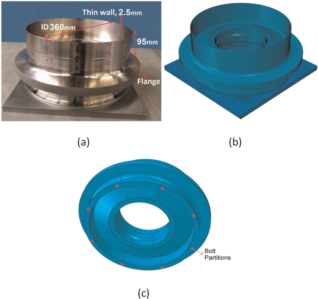
Casing used for studying tuned mass dampers: (a) casing geometry, (b) finite element model and (c) bottom view of casing showing partitions used as bolt surfaces, which are tied to the fixture plate.
FE analysis was carried out using standard commercial software ABAQUS®. The casing is meshed using a combination of hexahedral with reduced integration and tetrahedral elements to avoid phenomena such as shear and volumetric locking.
A frequency extraction step was carried out to determine the first 10 modes using the Lanczos solver. Harmonic analysis was carried out to study the workpiece response at all the extracted natural frequencies in which the thin wall casing participates. The harmonic response was computed using direct integration. Although this step is computationally expensive, it was chosen as it gives accurate results in the presence of material properties that depend on frequency – a characteristic of viscoelastic materials, which is also modelled as part of tuned damper. A structural damping factor of 0.1% was included in the analysis after preliminary experimental modal testing of the casing. The harmonic response of the undamped casing (Figure 2) shows the first few fundamental modes to be dominant. Experimental frequency responses were acquired on the casing in the machining set-up.
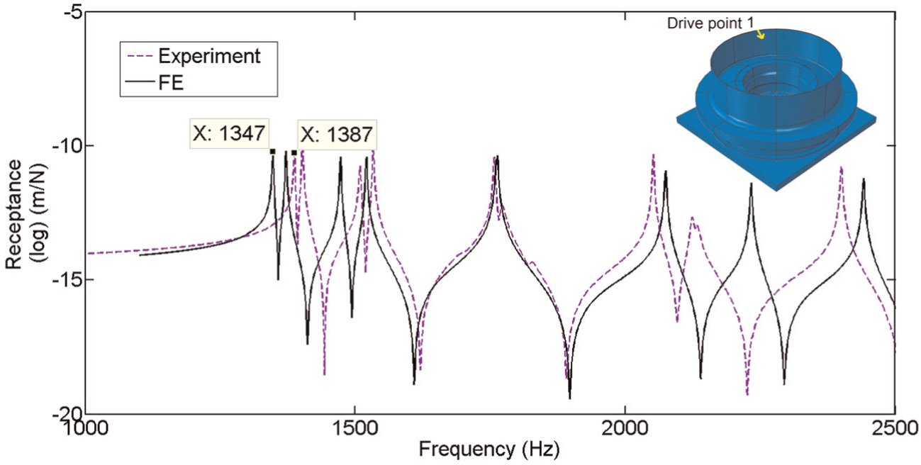
FE modelled and experimental driving point harmonic response of undamped casing (inset: response location on casing).
A comparison of experimental and FE frequency responses shows a good matching with a maximum error of 3% on first fundamental mode, which could be due to minor variation in material properties and can be corrected through model updating. However, in the present study, this accuracy was found acceptable and same FE model was used for tuned damper analysis. Having validated for undamped case, this FE model is then used for modelling and validating the tuned dampers.
FE analysis and validation for casing with tuned dampers
As reported in Kolluru and Axinte, 14 while milling a thin wall casing, the casing’s first fundamental mode is dominant at low and medium depths of cut, which are characteristic of finish machining operations. This is shown up as significant amplification of the tooth cutting frequency harmonic closer to the first fundamental mode. Damping of machining vibrations is more relevant in finishing as it can directly offer a significant improvement in product surface quality. Hence, in this study, tuned dampers were designed for workpiece fundamental mode and see its effect in damping the targeted mode as well as neighbouring modes. Vasques et al. 15 gave a detailed review of modelling and FE implementation of viscoelastic damping including mathematical descriptions of models and FE modelling approaches. In this research, 3M® ISD112 viscoelastic tape is used as it has a high loss factor and a moderate modulus value, and with a little variation of these values within the expected operational temperature range. Potvin 16 provided the frequency domain viscoelastic data for 3M ISD112 extracted from manufacturer’s data sheet and these are used in this simulation and reproduced in Table 1 of Appendix 1. Oyadiji 17 summarised the guidelines for static and dynamic analyses of viscoelastic materials using FEs.
Considering that the first fundamental mode of the casing is 1387 Hz, the experimentally designed viscoelastic dampers are tuned for this frequency. However, for FE analysis, 1347 Hz frequency was chosen for tuning the damper as it is the corresponding first mode of the casing. For a given target frequency, the design parameters are the mass of the damper block and thickness of viscoelastic tape. It is usual to take the damper block mass as 1%–5% of the vibrating mass 3 and calculate corresponding thickness of viscoelastic tape. The lower the mass of tuned damper, the tuning has to be more accurate and the system is less robust to variations in dynamic parameters of the system, an important factor in thin wall machining. For a casing with a locally vibrating structure such as a thin wall, such a local feature has to be considered as vibrating mass (in this case 4.47 kg). For a mild steel damper block with a mass equal to 5% of vibrating mass and dimensions of 40 × 40 × 20 mm, the thickness of viscoelastic tape was found out to be 1 mm. The mode shape of the 1347 Hz frequency to be damped, Figure 3, has six circumferential waves.
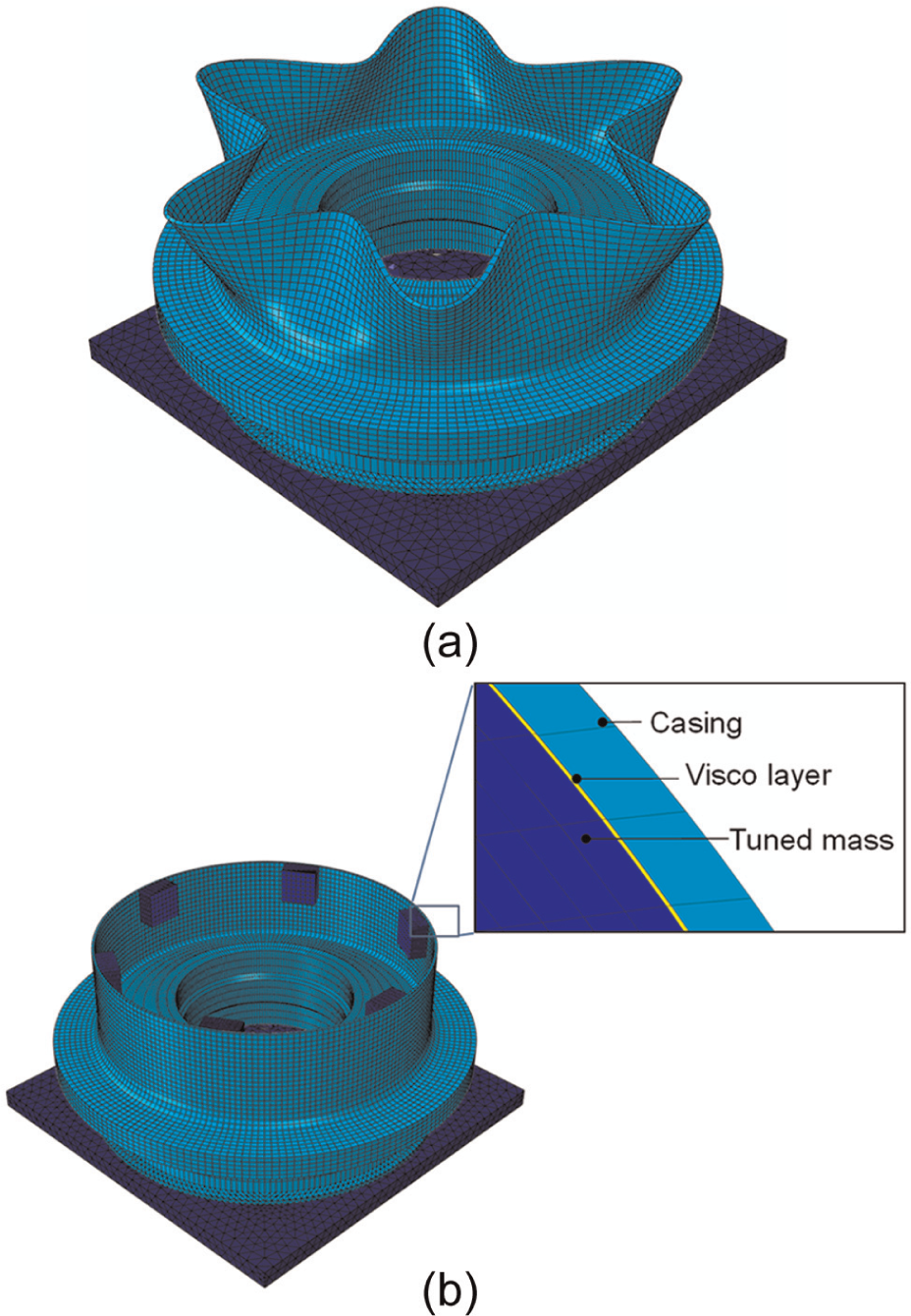
(a) First mode shape (1347 Hz) of casing and (b) corresponding arrangement of tuned dampers.
Preliminary analysis of mounting only one tuned damper revealed that while the targeted frequency was reasonably damped, other workpiece modes are excited during machining. Hence, a total of six tuned dampers corresponding to six anti-nodes of the first fundamental mode, as shown in Figure 3, are used with an intention to provide a higher mass ratio of dampers. The reason for choosing such a high mass ratio is to damp frequencies of casing over wider bandwidth as thin wall casings have significantly higher number of modes with similar magnitude across wide frequency range. For example, about 250 modes corresponding to thin shell of the casing exist up to 15 kHz. Moreover, in machining of thin wall casings, unlike rigid machine or tool structure where tuned masses were applied earlier, the forced vibration due to tool is significant. In such a situation, it is highly desirable to improve the mass of the vibrating structure so that the increased inertia forces tend to minimise the vibration amplitude.
A FE model, as shown in Figure 3(b), was created with these parameters for tuned masses and viscoelastic layer. The damper block was meshed using continuum elements, and the viscoelastic layer was meshed using hybrid continuum elements, which will give accurate results while simulating incompressible rubber-like materials, 17 such as the 3M ISD112 viscoelastic material used in this study. Figure 4 shows the harmonic response of the casing with six TMDs along with the experimentally obtained FRF. It can be seen that the amplitude of the response has decreased significantly, and the reasonably close matching of the FE and experimental FRFs indicate the accuracy in modelling the damping. This FE model can be further enhanced to include coupled interaction of tool’s frequency, thereby enabling the simulation of roughing operations where the tool’s frequency is dominant throughout the spectrum and also much accurate prediction of dynamic response in finishing with tool’s frequency, although less significant. In the next section, the quantified improvement in vibration reduction due to mounting of tuned dampers is presented along with the analysis of coupled interaction of tool and workpiece.
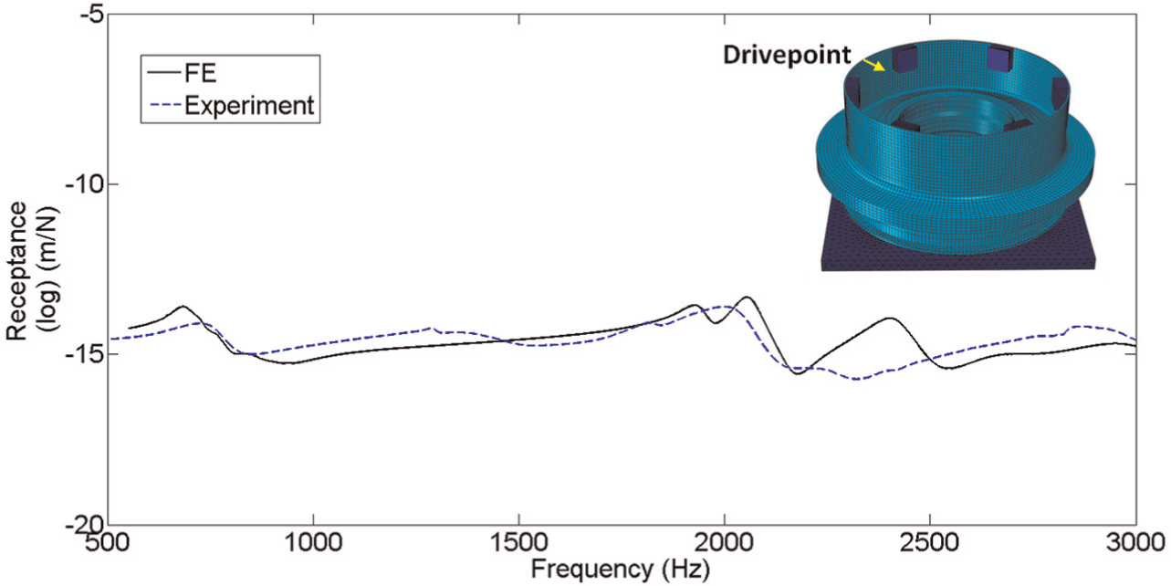
Harmonic response of casing with six tuned mass dampers.
Dynamic response analysis in milling of casing with tuned dampers
Improvements in vibration reduction
The casing with six tuned dampers is machined in similar set-up to that of undamped casing. As shown in Figure 5, one quadrant of casing was machined in four sectors to obtain data at various sections of casing with and without damper. Also the data being acquired at a higher sampling rate of 1 million samples per second, machining in four sectors makes data handling easier. The tool used is ∅16 mm with 2-flute and overhang was maintained constant at 46 mm for all the experiments, and the bending and torsion modes of tool for this overhang are 4800 and 17,000 Hz, respectively, as predicted from FE. The spindle revolutions per minute (rpm) is maintained at 800 r/min, which gives a cutting tooth frequency of 26 Hz. When the vibration signal is analysed for many revolutions of tool, this cutting tooth frequency and its harmonics can be seen. But as reported in Kolluru and Axinte 14 and Davies and Balachandran, 18 these harmonics will be strongly modulated by tool and workpiece modes. Analysing the signal for one revolution of tool offers insight into the coupled interaction of tool and workpiece frequencies. Considering that the casing is prone to higher vibration in between two damper blocks, the accelerometer is mounted between them, as shown in Figure 5, and correspondingly, the data acquired in sector II will be presented and discussed in this article. With the dampers mounted in place, the casing exhibited overall improvement in rigidity, which can be observed by the absence of high-frequency sounds (such as whistling) and machining characteristics akin to that of a rigid solid component.
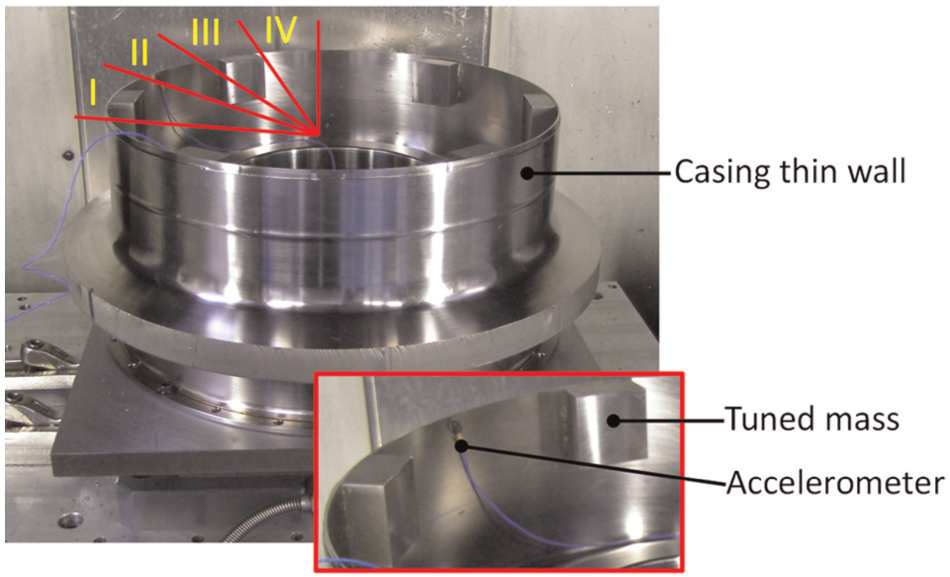
Experimental set-up of casing with six tuned dampers (inset: close-up view of accelerometer between dampers).
The efficacy of damper blocks in reducing machining vibration was evaluated by calculating the root mean square (RMS) value of the acceleration signal acquired during machining. Figure 6 shows the machining vibration signal acquired in sector II for ap = 2 mm and ae = 1 mm. It can be noted that the vibration reduction was significant in terms of RMS value – 2.29 times. This is significant from the fact that the entire signal was acquired in between two damper blocks. The reduction in vibration at the damper is still higher (about five times), but evaluation in between dampers represents worst case scenario. Machining tests were conducted at other depths of cut as well to evaluate the efficiency of dampers. Figure 7 shows vibration reduction for ap = 0.5 mm and ae = 0.5 mm, where it can be seen that the improvement is little more significant – about four times. This phenomenon could be due to lower excitation of tool’s forced vibration and also the excitation of workpiece (casing) modes at lower depth of cut, which are now adequately damped through the mounted masses. However, this will be determined through studying frequency content presented in the following sections. Apart from proving the effectiveness of the proposed solution, these results show that damping in thin wall machining is also dependent on the depth of cut (i.e. contact pressure between cutting edge and workpiece).
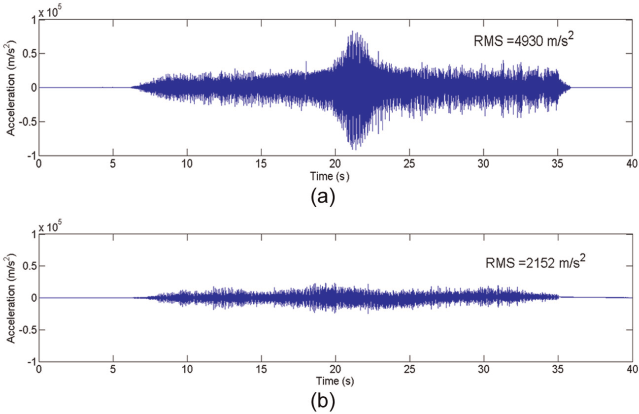
Example of vibration reduction when milling of thin wall casing at ap = 2 mm and ae = 1 mm: (a) undamped and (b) with tuned dampers.
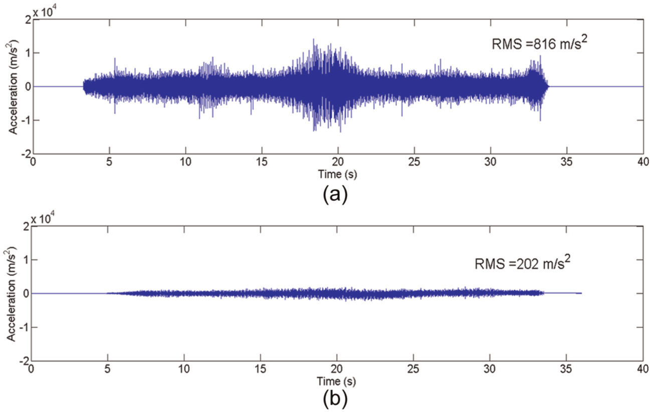
Example of vibration reduction when milling of thin wall casing at ap = 0.5 mm and ae = 0.5 mm: (a) undamped and (b) with tuned dampers.
Analysis of coupled interaction between tool and workpiece with tuned dampers
To study the frequency content and thereby understand the coupled interaction between tool and workpiece in the presence of tuned dampers, time–frequency analysis was carried out on the acquired acceleration signals. For all the analyses, the signal closest to the accelerometer is considered as it would give the direct vibration near to the tool tip and hence an indication of effect of damping in the machining zone. Fast Fourier transformation (FFT) was carried out on the acceleration signal for one revolution of tool at various sections of 0.005 s each; the acceleration signals shown in Figures 6 and 7 are used for this purpose. The detailed methodology of this procedure is reported in Kolluru and Axinte. 14 Figure 8 shows the 3D time–frequency plot for acceleration signal of ap = 2 mm and ae = 1 mm.
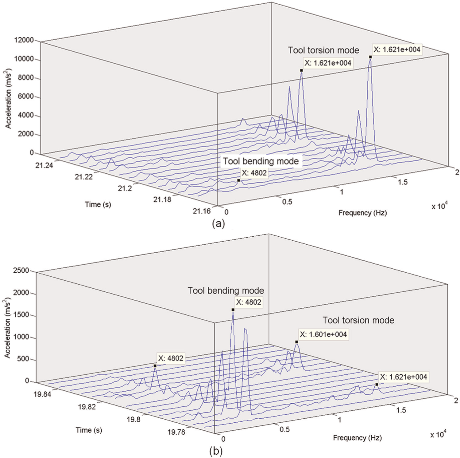
Time–frequency analysis of acceleration signal when milling casing at large depth of cut (ap = 2 mm and ae = 1 mm): (a) undamped and (b) with tuned dampers.
It can be observed that in undamped casing frequency spectra (Figure 8(a)), the harmonics of tooth cutting frequency near the tool torsion mode are significantly dominant. However, for the sake of clarity in explaining the results, these harmonics are henceforth referred in this article as the frequency near which they are excited. For example, the harmonics that are distinctly excited near to tool torsion mode are referred to as tool torsion mode frequency only. These frequencies need not be same as the original resonant frequencies near to which they are excited as they are harmonics of the tooth cutting frequency. From Figure 8(a), it can also be observed that tool bending mode and fundamental workpiece frequency are excited but dwarfed by the excitation of torsional mode. The continuity in excitation of torsional mode even after the disengagement of cutting tooth indicates the strong forced vibration of tool imparted onto the workpiece. This shows a strong coupling of tool’s torsional mode with that of the workpiece.
With the damper blocks in place (Figure 8(b)), the important feature that can be noted is that the tool bending mode, which was not dominant in undamped casing, is distinctly dominant, and that the torsional mode is no longer significantly dominant. Acceleration signal corresponding to other tool revolutions near to the accelerometer showed similar pattern with varying amplitudes of the tool torsional mode, but always comparable or less than that of the bending mode excitation. This is an interesting observation as it shows a change in coupling interaction of the workpiece to the tool’s frequencies. This could be explained as follows: in undamped condition, due to the inherent stiffness of the casing in the tangential direction, the tool’s torsional mode significantly couples with the workpiece. With the mounting of damper blocks intermittently, the section of the casing in between two blocks acts more like a cantilever fixed at both ends and thereby offering dynamic characteristic similar to that of a straight thin wall. This characteristic is then responsible for coupling of tool’s bending mode with the workpiece. This also matches with the observation that while milling straight thin walls, tool’s bending mode couples with workpiece, as reported in Kolluru and Axinte. 14
From Figure 8(b), it can be noted that most of the workpiece modes, including the fundamental modes, are significantly damped indicating a damping effectiveness over wide bandwidth due to higher mass ratio of dampers. However, the continuity of tool’s forced vibration (of bending and torsional modes) even after disengagement of cutting tooth indicates a strong coupling of tool and workpiece due to the forced vibration. Similar analysis was carried out on acceleration signal with ap = 0.5 mm and ae = 0.5 mm, and the results are presented in Figure 9. The lower depth of cut excites tool’s forced vibration to lesser extent and hence the dominant appearance of workpiece modes. In addition to the fundamental mode, the workpiece modes near the tool torsional mode are also excited. Mounting the dampers leads to similar observation (Figure 9(b)), as that of higher depth of cut (ap = 2 mm and ae = 1 mm) – dominant participation of tool’s bending mode as compared to torsional mode. Although few workpiece modes do not seem to be sufficiently damped, it may be noted that the targeted mode of 1387 Hz was totally damped, and that the magnitude scale is so small that other workpiece modes look significant. As can be seen, these modes are excited only during the instance of cutting tooth engagement and quickly get damped after tool disengagement. Thus, both the cases showed that a change in coupled interaction of workpiece and tool’s dynamic response is involved with the mounting of tuned dampers.
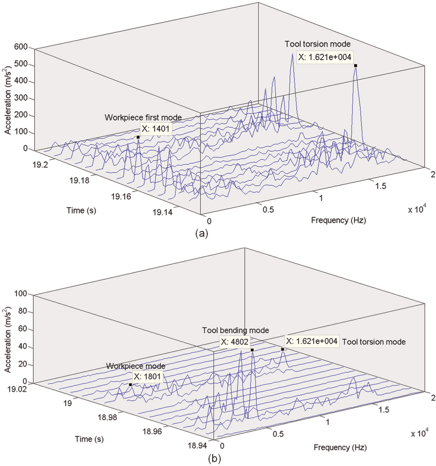
Time–frequency analysis of acceleration signal when milling casing at small depth of cut (ap = 0.5 mm and ae = 0.5 mm): (a) undamped and (b) with tuned dampers.
To study the effect of such a variation in coupling from torsional to bending mode, the thickness of machined thin wall of casing was measured. Machining trials were conducted in third and fourth sectors of the casing, as shown in Figure 5, thereby covering an area with and without tuned mass. Axial and radial depths of cut of 2 and 1 mm were used to achieve a wall thickness of 1.5 mm. The thickness variation measured on the casing thin wall, as shown in Figure 10, clearly shows that in between the damper blocks, the thickness is different by 70 µm as compared to the area where damper block is situated. This can be explained from the observation made by Bravo et al. 19 that in down milling of thin wall, the cutting force tends to push away the thin wall relative to the tool. In the present case of thin wall casing with intermittent damper blocks, the casing is locally acting as a cantilevered thin wall with rigid damper blocks at either end. Hence, the casing thin wall is pushed away from tool resulting in higher thickness as compared to the location where the damper mass is situated.
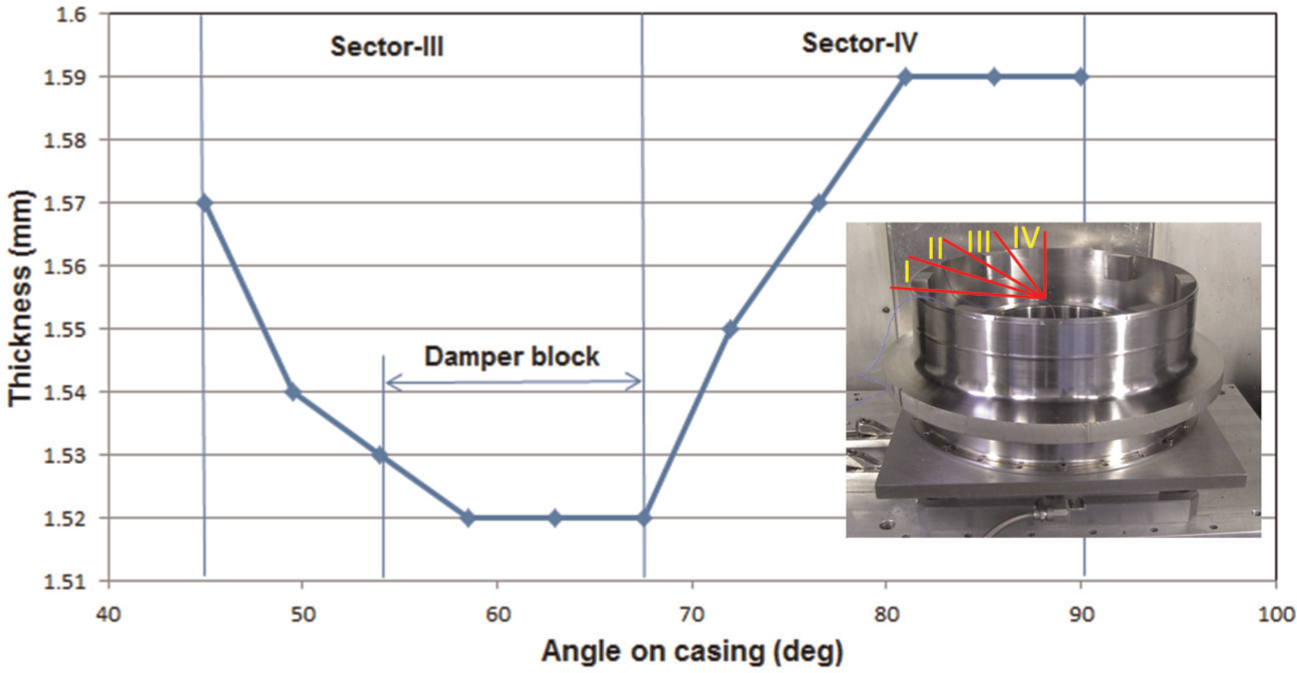
Thickness variation of thin wall of casing in sectors 3 and 4.
Conclusion
The damping of machining vibrations is a crucial factor in achieving improved product surface quality and enabling improvements in productivity via higher material removal rates. Thin wall ring-type structures can be susceptible to workpiece vibrations during machining, and passive damping treatments are potential solutions to address this problem. In this article, the effect of viscoelastic dampers, tuned for the workpiece fundamental mode, on the coupled interaction was studied along with its effect on varying depths of cut. Moreover, a FE model was developed to investigate the effect of damper on ring-type casing in minimising the targeted workpiece mode only. While tuned dampers were not attempted previously to minimise machining vibrations on thin wall structures, study of the coupled interaction between tool and workpiece in the presence of dampers also was not reported. Hence, the findings of this study are interesting from the perspective of understanding impact dynamics in milling thin wall closed geometry structures without and with the presence of tuned dampers. Major findings of this study are highlighted in the following:
With the application of tuned dampers, the targeted workpiece fundamental mode was totally damped and the neighbouring modes were also significantly damped owing to high mass ratio used for the dampers.
After damping the targeted mode, the coupled tool’s resonant frequency persisted though at a much lower amplitude. However, with the mounting of the dampers, unlike in an undamped casing, this coupling has changed from tool’s torsional mode to bending mode. This could be possibly due to creation of an effect of cantilevered thin wall between the two damper blocks. As previously reported, a straight cantilever thin wall couples with tool’s bending mode, and this effect was observed for the machining trials carried out on casing thin wall between two damper blocks. The presence of coupled tool’s bending mode on workpiece even after disengagement of cutting tooth showed the strong coupling between tool and workpiece.
The change in coupling from torsional mode of the tool to bending mode is reflected in the thickness variation of the machined thin wall of casing. The wall thickness of casing between the damper blocks is found to be 70 µm more than that at the damper block. This can be attributed to the relative movement of the thin wall away from tool due to action of cutting force. This result reinforces the observation that casing thin wall acts as a cantilever in between two damper blocks.
On comparing the damper effectiveness at different depths of cut, low depth of cut showed slightly higher reduction in vibration in terms of RMS value owing to the presence of lesser forced vibration of tool’s frequency on the casing.
FE prediction of dynamic response for thin wall casing with and without tuned dampers showed satisfactory agreement with that of experimental impact hammer testing results. The fact that the prediction was matching indicates the feasibility of its usage for workpiece damping solutions such as in finish machining operations. However, for a successful prediction of dynamic response for roughing operations (characterised by higher depths of cut), where tool’s mode is strongly coupled than workpiece modes, FE modelling of tool and its dynamic coupling with workpiece need to be taken up, which will be pursued as future study.
This article thus offers an understanding in the mechanism of dynamic coupling of tool–workpiece responses, while machining thin wall closed geometry structures, which can be applied in modelling the impact dynamics with dampers. Such a modelling is of key importance for simulating passive and active damping solutions for industrial applications such as machining of a wide range of casings for high value-added industries such as aerospace.
Footnotes
Appendix 1
Frequency domain data for viscoelastic material 3M® ISD112. 16
| Frequency (Hz) | Storage modulus (Pa), G′ | Loss factor, η |
|---|---|---|
| 0.1 | 7.00E+04 | 0.4 |
| 0.5 | 1.00E+05 | 0.6 |
| 1 | 1.40E+05 | 0.7 |
| 2 | 1.70E+05 | 0.8 |
| 3 | 2.00E+05 | 0.85 |
| 4 | 2.10E+05 | 0.9 |
| 5 | 2.40E+05 | 0.9 |
| 10 | 3.40E+05 | 1 |
| 20 | 5.00E+05 | 1 |
| 50 | 7.50E+05 | 1 |
| 70 | 9.00E+05 | 1 |
| 100 | 1.00E+06 | 1 |
| 200 | 1.60E+06 | 1 |
| 500 | 2.50E+06 | 0.9 |
| 700 | 3.00E+06 | 0.9 |
| 1000 | 3.50E+06 | 0.85 |
| 5000 | 7.00E+06 | 0.6 |
| 10,000 | 9.00E+06 | 0.5 |
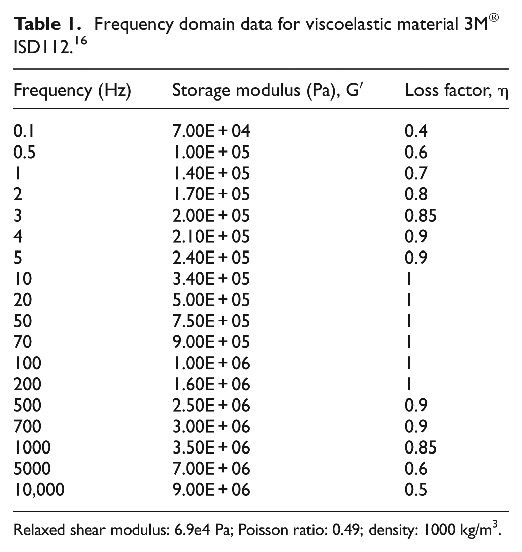
Relaxed shear modulus: 6.9e4 Pa; Poisson ratio: 0.49; density: 1000 kg/m3.
Acknowledgements
The authors would like to thank Mr Peter Winton from Rolls-Royce for his support through discussions and reviews. Special thanks also go to Stuart Branston and Mark Daine of University of Nottingham for supporting all the experimental activities reported in this study.
Declaration of conflicting interests
The authors declare that there is no conflict of interest.
Funding
This study was funded by the EPSRC and Rolls-Royce under Dorothy Hodgkin Postgraduate Award scholarship under grant number EP/P505917/1 to undertake this research.