
Abstract
Integrating ceramic shell and ceramic core for the fabrication of gas turbine blade is a promising method based on stereolithography and gelcasting technologies. But the cracking in the integral Al2O3-based ceramic mold takes place readily during casting process. The effect of hydrostatic pressure and thermal shock resulting from high-temperature liquid metal on the stress in Al2O3-based ceramic mold was respectively investigated, and the thickness of ceramic shell was also studied. The results show that the thermal stress is the main reason for the cracking in Al2O3-based ceramic mold, and the thickness of ceramic shell has a significant effect on thermal shock of liquid metal. The optimal value of Al2O3-based ceramic shell thickness is 9 mm so as to decrease its thermal stress effectively. Compared with micron-sized Y2O3 powders, nano-Y2O3 powders are more beneficial to improve high-temperature fracture strength of Al2O3 ceramic mold. Finally, a gas turbine blade is successfully fabricated.
Introduction
The turbine blade is a key component of gas turbine, and the complexity of its cooling channels and fine film cooling holes makes the manufacture of turbine blades very difficult via traditional investment casting process. 1 Consequently, many new methods are constantly being investigated, 2,3 in which large area maskless photopolymerization (LAMP) is a rapid manufacturing technology that is being developed at Georgia Tech. LAMP technology directly fabricates complex ceramic molds with integral cores for airfoil investment casting from computer-aided design (CAD) files layer-by-layer. 4 The aluminum-filled epoxy (EP) resin and silicon rubber molds were fabricated using stereolithography (SL) master models, and then several wax patterns were made by injection in the molds, which were utilized for ceramic shell fabrication and blade casting. The indirect rapid tooling (RT) techniques indicated that they enabled new cost-effective solutions for small batch production of gas turbine blades. 5 Chen et al. 6 and Wu et al. 7 put forward the integral fabrication technique of ceramic mold (IFTCM) in 2006, which was based on SL and gelcasting technologies. The wax patterns were replaced by SL patterns to overcome the disadvantage of time-consuming and cost-consuming in investment casting. 8 In order to overcome the disadvantage of assembly errors, the gelcasting technique was also involved to integrate ceramic shell and ceramic core. 9
In addition to the fabrication techniques of turbine blade, the material of its ceramic mold has been the research emphasis. Compared with fused silica ceramic, alumina ceramic has better high-temperature chemical stability and creep resistance. 10,11 Consequently, Al2O3-based ceramic composites were increasingly adopted for fabricating ceramic molds of turbine blade. But the porosity of integral ceramic molds fabricated by IFTCM in this article is so high that their high-temperature strength is lower, which easily causes the ceramic shell to crack during the casting process of turbine blade. Unfortunately, nearly no literatures are reported about the investigation into the cracking of Al2O3-based ceramic mold during the casting process of turbine blade.
In order to avoid the cracking of ceramic mold of turbine blade, its high-temperature fracture strength was usually increased. Some additives such as polymers and organic fibers were adopted. 12,13 A vacuum impregnating and resintering process was also developed to improve the high-temperature properties of Al2O3-based ceramic mold with micron-sized Y2O3 additive. After the specimens were twice dipped into aqueous yttria sol in vacuum, the flexural strength at 1550 °C was increased to 3.5 MPa or so, which could not usually meet the requirement of the casting of gas turbine blade with large dimension. 7 ProCAST is a general finite element analysis (FEA) solver for casting process, by which the fluid field, thermal field, and stress field can be calculated simultaneously. Therefore, the cracking of Al2O3-based ceramic mold could be effectively analyzed. Hong et al. 14 used ProCAST software to simulate the thermal stress during directional solidification of simple hollow blades, and the predicative residual stress correlated well with his experimental results. However, thermal stress calculation of molds has been rarely reported.
Thermal behaviors of integral Al2O3-based ceramic molds for turbine blades will be investigated during casting process in this article. Initial stress calculations of the hydrostatic pressure and thermal shock will be made in ProCAST. Then the thickness of ceramic shell will be studied in detail in order to optimize the design of ceramic mold. In addition, nano-Y2O3 will be added to improve the high-temperature fracture strength and meet the high-temperature requirements of casting. Finally, a gas turbine blade will be fabricated by the integral ceramic mold method.
Experiment
Materials
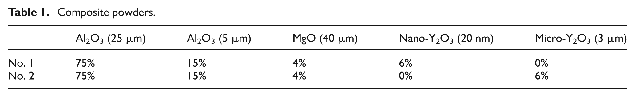
Table 1 shows the mass ratio of composite powders. Irregular fused alumina powders with different particle sizes (D50 = 5 and 25 µm, purity = >99.32%) were adopted, MgO (D50 = 40 µm, purity = 99.99%) and Y2O3 (D50 = 3 µm and 20 nm, purity = 99.99%) powders were added as mineralizers, and water-based yttria sol (mass concentration: 15%; yttria particle size: 3 nm) was used for impregnation. Acrylamide (AM) and methylenebisacrylamide (MBAM) (the mass ratio of 24:1) were used as the organic monomer and the cross-linker, respectively. Additionally, trace of sodium polyacrylate (3.5 wt% of solid powders) was used as dispersing agent, and proper trace of initiator (ammonium persulfate) and catalyst (tetramethylethylenediamine) were adopted, which were 1.5 and 0.3 wt% of the premixed solution, respectively. The premixed solution with the concentration of 25% was prepared by dissolving AM and MBAM in deionized water.
Composite powders.
Sample preparation
Figure 1 shows the main fabrication process of gas turbine blade, which includes CAD modeling (Figure 1(a)), SL (Figure 1(b)), gelcasting (Figure 1(c)), freeze-drying, presintering, impregnating, sintering, and so on (Figure 1(d)). 7 SL prototype was first fabricated by SPS450B (developed by Xi’an Jiaotong University, China). Ceramic slurry containing solid powders in above solution of organic monomers was then prepared for gelcasting according to section “Materials,” and the solid loading of ceramic slurry was about 56 vol.%. Subsequently, the slurry was poured into the SL mold and in situ polymerized to form ceramic green bodies. The freeze-drying process, 7 presintering, impregnating, and high-temperature sintering were conducted to obtain integral ceramic molds and testing samples. In presintering, the ceramic bodies were heated to 300 °C at about 10 °C–20 °C/h, from 300 °C to 600 °C at about 30 °C/h, then holding 30 min, from 600 °C to 1250 °C at about 360 °C/h, then holding 5 h, furnace cooling. In impregnating, the specimens were treated with vacuum of about 600 Pa for 15 min, taking out and freeze-drying them, then resintering to 1000 °C and keeping for 1–2 h (heating rate: 300 °C–360 °C/h). Finally, high-temperature sintering, 7 vacuum casting, and so on were conducted for fabricating gas turbine blade.
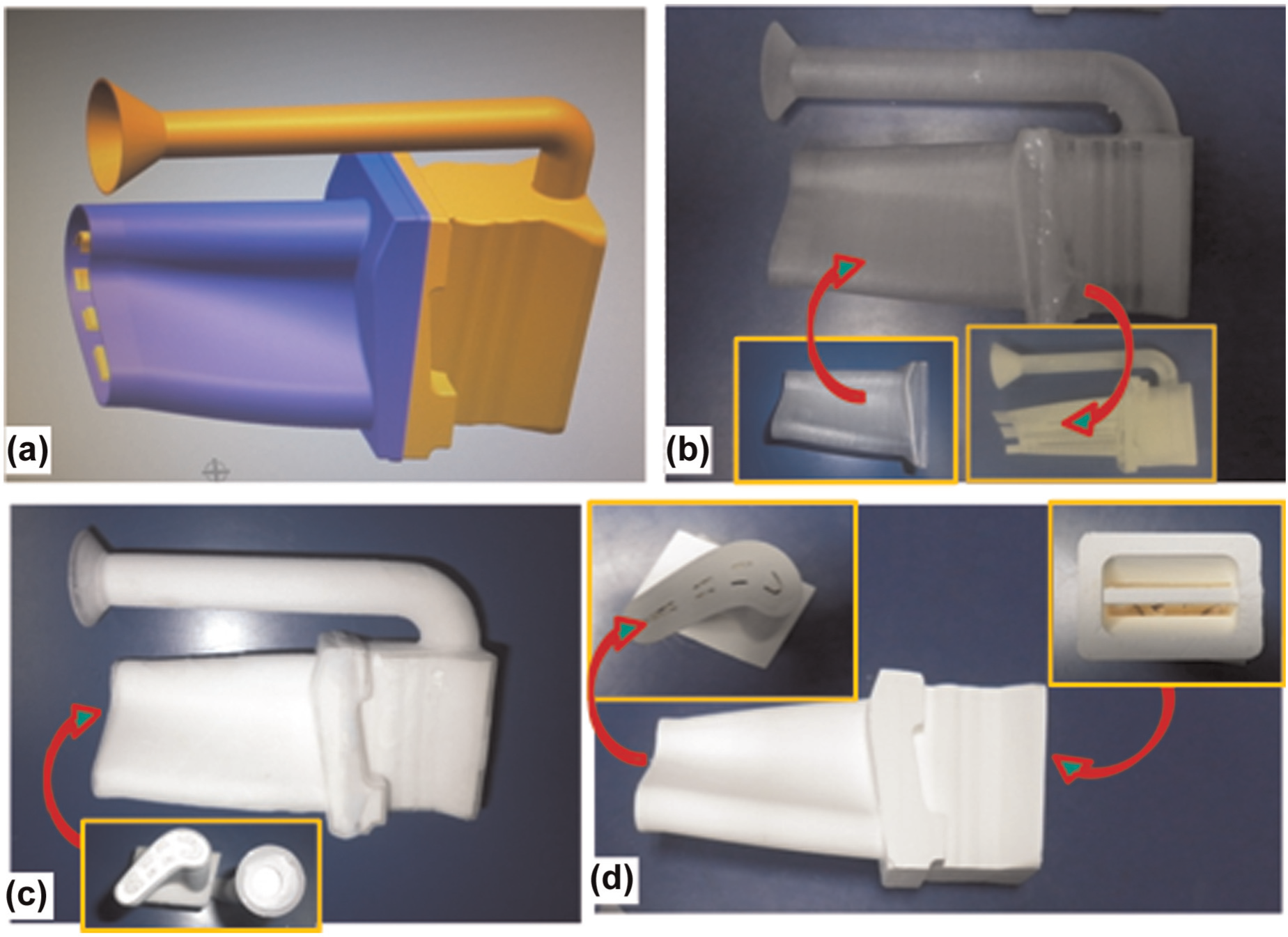
Fabrication procedures for integral ceramic mold: (a) CAD modeling, (b) SL, (c) gelcasting, and (d) freeze-drying, presintering, impregnating, and sintering.
Measurements
Mechanical properties
In order to measure three-point flexural strength, testing samples (4 × 10 × 60 mm) were prepared using the process presented in Figure 1. Every five samples were heated to 700 °C, 800 °C, 900 °C, 1000 °C, 1050 °C, 1200 °C, 1300 °C, and 1400 °C, respectively, and then held 30 min at the test temperature.
In order to calculate elastic modulus of the samples by the strain–stress curve, testing samples (Φ20 × 50 mm) were also respectively heated to 700 °C, 800 °C, 900 °C, 1000 °C, 1050 °C, 1200 °C, 1300 °C, and 1400 °C in CHY-1600 (Xiangyi Ltd, Xiangtan, China). Preload was imposed to samples along the length direction, which increased from 0 to 200 N every 20 N; the strain was recorded automatically by digital micrometer. Finally, the phase of integral Al2O3-based ceramic molds was determined by X-ray diffraction (XRD-6000; Shimadzu Corporation, Kyoto, Japan).
Thermal properties
Thermodynamic property
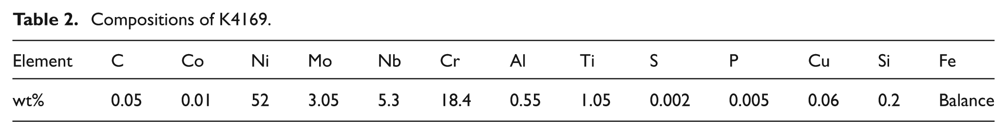
Alumina was assigned to the mold in ProCAST Material database. The casting material is called K4169 in China and is not included in ProCAST. Fortunately, ProCAST has an automatic link with thermodynamic databases to calculate thermal properties. It is thus possible to compute the enthalpy curve, the fraction of solid curve, the density, the viscosity, and the thermal conductivity on the basis of the chemical composition of Ni-based superalloy K4169, which is shown in Table 2. 15,16
Compositions of K4169.
Thermal expansion
Thermal expansion curves were drawn using a thermal dilatometer (PCY-1600; Xiangyi Ltd, China). The specimen (diameter: 6 mm; length: 50 mm) was heated to 1500 °C at a rate of 8 °C/min and then cooled to room temperature. Thermal analysis was performed five times so that its mean value was obtained.
FEA of integral ceramic mold
Hydrostatic pressure of high-temperature molten metal
Modeling and meshing
Only meshes of ceramic mold are needed for hydrostatic pressure analysis. However, meshes of both the casting and the mold are used to calculate thermal stress in ProCAST software during the casting process. If the elements on either side of an interface (i.e. adjacent elements that belong to casting and mold) share the same nodes, this is called a coincident mesh. And coincident meshes could improve numerical accuracy and stability of three-dimensional (3D) finite element method (FEM) analysis compared with non-coincident meshes. Therefore, coincident meshes should be generated first to calculate thermal stress. Then the elements of molds could also be used to calculate hydrostatic pressure.
The gate system of turbine blade and integral ceramic mold was first modeled in UG software. Then geometry information was imported to Hypermesh software for volume mesh generation. The turbine blades had a complex internal and external structure, especially for complex interior cooling passages. Tetrahedron elements were used to precisely reflect the geometry of ceramic mold.
The procedure is shown in Figure 2. Local surface meshes of casting were first precisely generated with more elements around small features. Then surface meshes of casting were assembled by local ones completely. Finally, 3D volume tetrahedron meshes controlled by enclosed surface elements were generated. In this method, a relatively small number of meshes (190,000) with the aspect ratio below 6 were obtained.
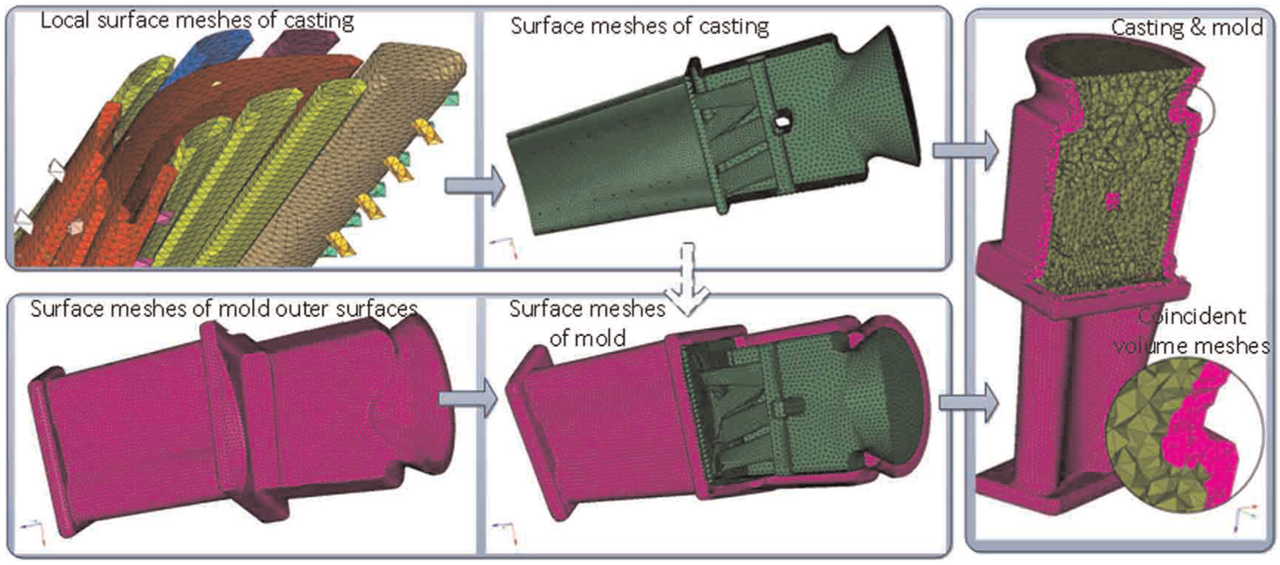
Procedures to generate coincident volume meshes of casting and mold.
To generate coincident volume elements of mold, outer surfaces of mold were first input to Hypermesh, and two-dimensional (2D) surface meshes were generated on these surfaces. Then, surface meshes of the casting were copied to the component, which was used to organize the elements and geometry of the mold. Together with outer surface elements generated before, all the 2D surface elements were enclosed to form the mold. Finally, these 2D surface elements were used to generate volume elements of mold. Therefore, interface between casting and mold shared the same nodes and elements. For hydrostatic pressure analysis, the 3D volume meshes of mold were exported from Hypermesh to ANSYS and element type SOLID45 was defined to them.
Loading and solving
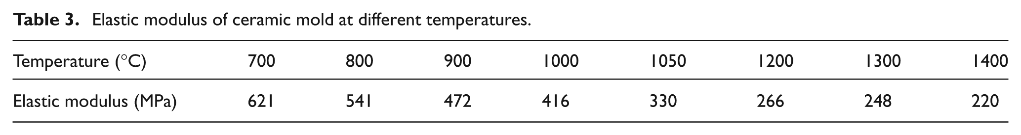
Ceramic mold was preheated to 1050 °C before casting, and the elastic modulus at this temperature was 330 MPa in Table 3. Poisson’s ratio ν = 0.27 and density ρ = 2300 kg m−3 were set for the ceramic mold. A pressure load was applied to inner surface of the mold with the direction perpendicular to it; the scaling of the pressure was described as a function of height P = ρgh, where density ρ is 7920 kg m−3, acceleration of gravity g is 9.8 m s−2, and h is the depth of liquid metal.
Elastic modulus of ceramic mold at different temperatures.
After the constraints in Z direction on the bottom surface of the mold and gravity were applied, a solving procedure was implemented. The variation rule of the maximum principal stress was then obtained by HyperView.
Thermal stress during casting process
PreCAST (preprocessing of ProCAST)
Most of the preprocessing operations are performed in PreCAST, which is a key component of ProCAST software. Material thermodynamic properties of K4169 were obtained in PreCAST.
Table 3 shows elastic modulus of ceramic mold, and Poisson’s ratio and thermal expansion coefficient were set to 0.27 and 8.0 × 10⁻⁶ /°C, respectively. Table 4 shows other preprocessing parameters, which were set for both ceramic mold and casting. Related control settings were properly defined to solve the flow, temperature, and stress field during casting process. The solver was terminated when the temperature of both casting and mold was below 1250 °C.
Preprocessing parameters.
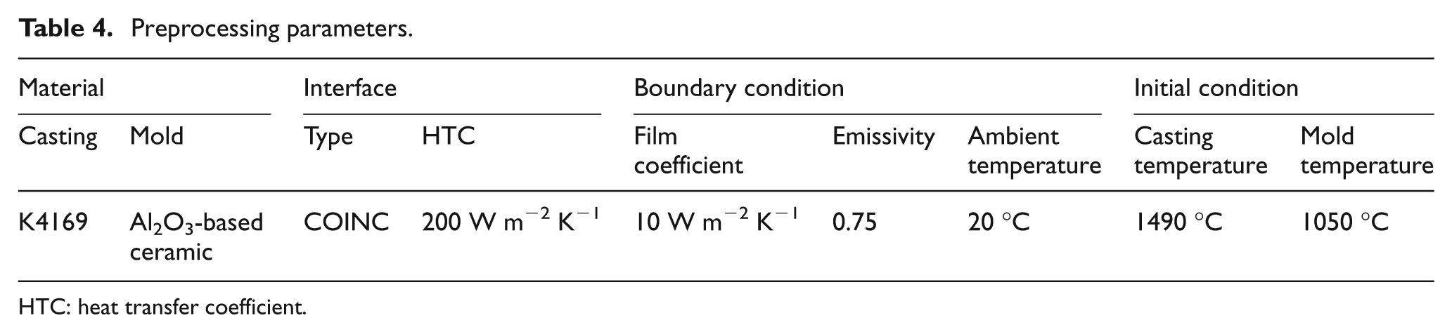
HTC: heat transfer coefficient.
Table 4 shows the parameters used in simulation, in which heat transfer coefficient (HTC) was referenced, 14 and others were set according to the actual process situation.
Results and discussion
Hydrostatic pressure and thermal stress
Figure 3(a) shows the distribution of the maximum principal stress in Al2O3-based ceramic mold of 12 mm thickness when the hydrostatic pressure resulting from high-temperature liquid metal is only taken into account. The stress is close to 0 at the upper half of the mold while it is a little bigger at the lower half of the mold. Figure 3(b) shows certain cross section of the mold, whose location is shown in Figure 3(a), and the maximum stress of 0.73 MPa appears on blade trailing edge, which is marked by black circle. But the cracking during the casting process usually occurs at the upper half of the mold in Figure 3(c). Since the fracture strength of Al2O3-based ceramic mold at 1050 °C–1500 °C was not less than 4 MPa, the cracking in ceramic mold will not take place when the maximum stress is 0.73 MPa, which only results from hydrostatic pressure. So the hydrostatic pressure is not the main reason of mold cracking during the casting process.
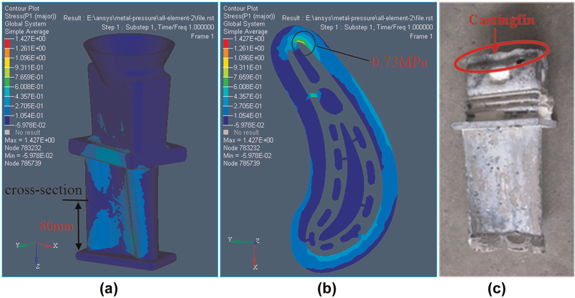
Stress distribution caused by hydrostatic pressure and experiment: (a) stress result, (b) cross-sectional result, and (c) casting defect caused.
Figure 4(a) shows that the maximum principal stress at positions A–E is bigger than any other regions, so these five points are mainly investigated. Thermal stress at different positions is shown in Figure 4(b), and the stress at point A is bigger than any other points. Therefore, it is the most dangerous area of the mold. Besides, the stress on every point increases with time significantly after 100 s and reaches 20 MPa quickly. When the high-temperature flexure strength of ceramic shell is not more than 20 MPa, the ceramic shell will crack during the casting process.
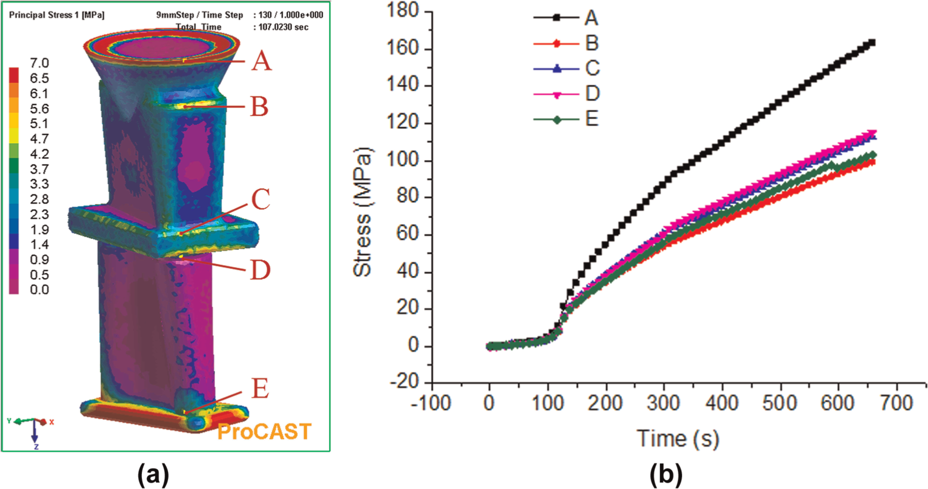
Thermal stress of ceramic mold: (a) distribution of thermal stress and (b) thermal stress at different positions.
Because the thermal expansion-induced thermal stress is remarkably larger than the stress resulting from hydrostatic pressure of liquid metal, the thermal stress is thought to be the main reason causing shell to crack.
Fabrication
Ceramic shell thickness
The thickness of integral Al2O3-based ceramic shell is uniform and a key structural parameter, which has a great influence on temperature distribution in ceramic shell. So, the thickness of ceramic shell is an influence index on thermal stress in ceramic shell.
The thickness of ceramic shell is generally 5–15 mm in the investment casting. The thermal stress in ceramic shells was calculated in this article, whose thickness is 6, 9, 12, and 15 mm, respectively. Figure 5 shows that the thermal stress varies with time. The thermal stress of 6-mm-thick shell is the biggest, while others have a trend that the larger the shell thickness, the greater the thermal stress. Take thermal stress of 12-mm-thick ceramic shell as an example: the blue plot in Figure 6 shows the lowest solid fraction of casting surface. Critical solid fraction (the solid fraction when liquid metal with no fluidity) of Ni-based superalloy is generally considered to be 0.6. When the solid fraction of casting surface reaches the critical solid fraction, the largest stress of shell is 11.2 MPa, at point A, and the highest temperature of shell is 1300 °C. That is, only when the strength of 12-mm-thick shell is higher than 11.2 MPa at 1300 °C, the integrity of casting will be guaranteed. Its strength of 8.0 MPa is lower than the required strength of 11.2 MPa. Thus, the ceramic shell will inevitably crack.
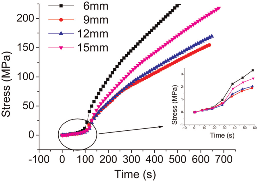
Thermal stress of different thicknesses at position A.
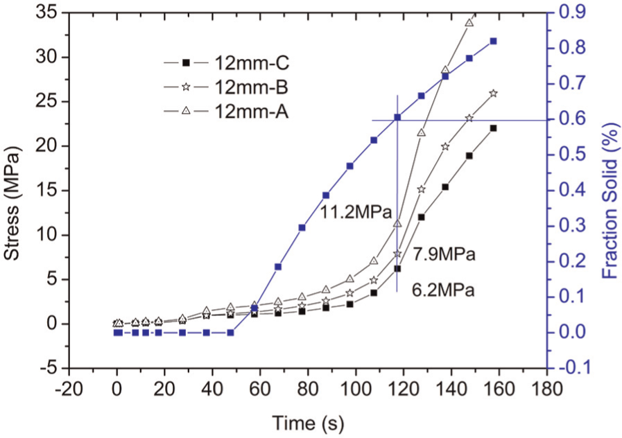
Thermal stress and fraction solid shells with the thickness of 12 mm.
Table 5 shows the critical stress calculated according to the critical solid fraction, and obviously, the strength requirement of 9-mm-thick shell is smallest, which is the optimal shell thickness. Thermal stress in shell results from temperature difference at different positions of the shell. During the casting process, unsteady temperature fields of the casting are influenced by many factors, including the changing thermodynamic parameters of metal under different temperatures, the temperature-dependent heat conductivity of shell material, the environmental radiation, and convection cooling condition of the shell outer surface. Additionally, irregular geometry and different thicknesses of shell will also considerably affect the cooling condition of outer surface and temperature distribution in the shell, which lead to different thermal stresses. This is the reason that 9-mm-thick shell has the smallest critical thermal stress.
Critical stress of different thicknesses.
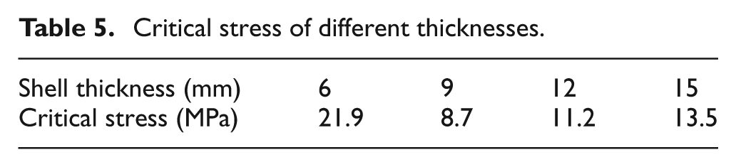
Considering that the thermal stress of 8.7 MPa is still higher than shell’s strength of 5.3 MPa, the shell will crack consequently when casting. Hence, the high-temperature fracture strength of mold should be increased by which the cracking in Al2O3-based ceramic mold can be prevented mainly resulting from thermal stress.
High-temperature fracture strength of ceramic shell
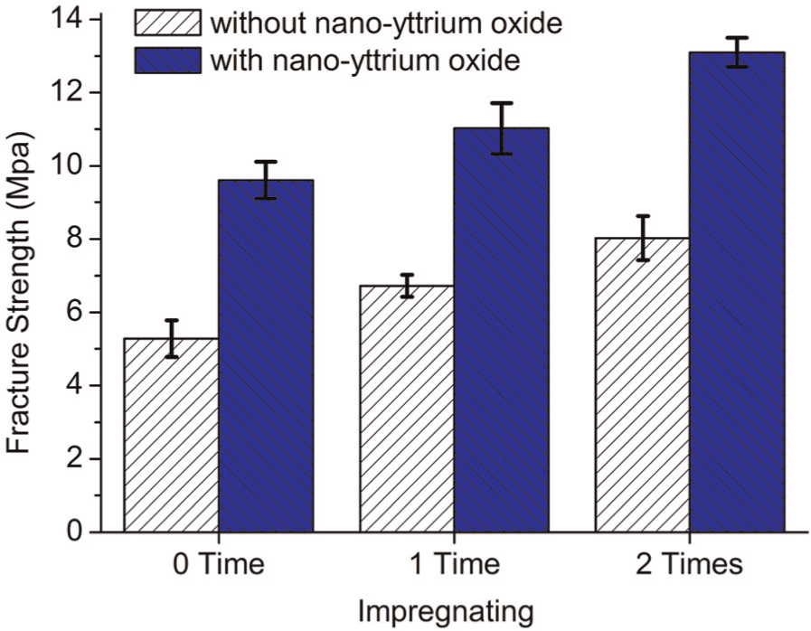
As we discuss above, the flexure strength of Al2O3-based ceramic shell at 1300 °C should be bigger than 8.7 MPa. Actually, the flexure strength of ceramic shell is 5.3 MPa, which is shown in Figure 7. To prevent Al2O3 ceramic mold from cracking during casting, the effect of two kinds of yttrium oxide (D50 = 3 µm and 20 nm) on its flexure strength was contrastively analyzed. The high-temperature flexure strength of ceramic mold with nano-Y2O3 additive can reach 9.6 MPa in Figure 7, which has already met the minimal flexure strength requirement of 8.7 MPa. The high-temperature flexure strength of Al2O3 ceramic mold will reach 13.1 MPa when it is impregnated twice, which may prevent the Al2O3 ceramic mold from cracking during casting.
Fracture strength of ceramic mold at 1300 °C after impregnating.
Figure 8 shows the XRD patterns of ceramic samples. After high-temperature sintering, Al2O3 reacted with sintering aid MgO and formed magnesium aluminate spinel (MAS; MgAl2O4); Al2O3 reacted with sintering aid Y2O3 and formed yttrium aluminum garnet (YAG; Y3Al5O12) and other mesophase (Al2Y4O9 and YAlO3). By replacing yttrium oxide of 3 µm with nano-yttrium oxide of 20 nm, the content of high-temperature strengthening phase YAG increased from 4 vol.% to 10 vol.%. The high-temperature flexure strength of Al2O3 ceramic mold was improved because the surface activity of nano-powders was higher than that of micron powders, which contributed to the sintering among powders.
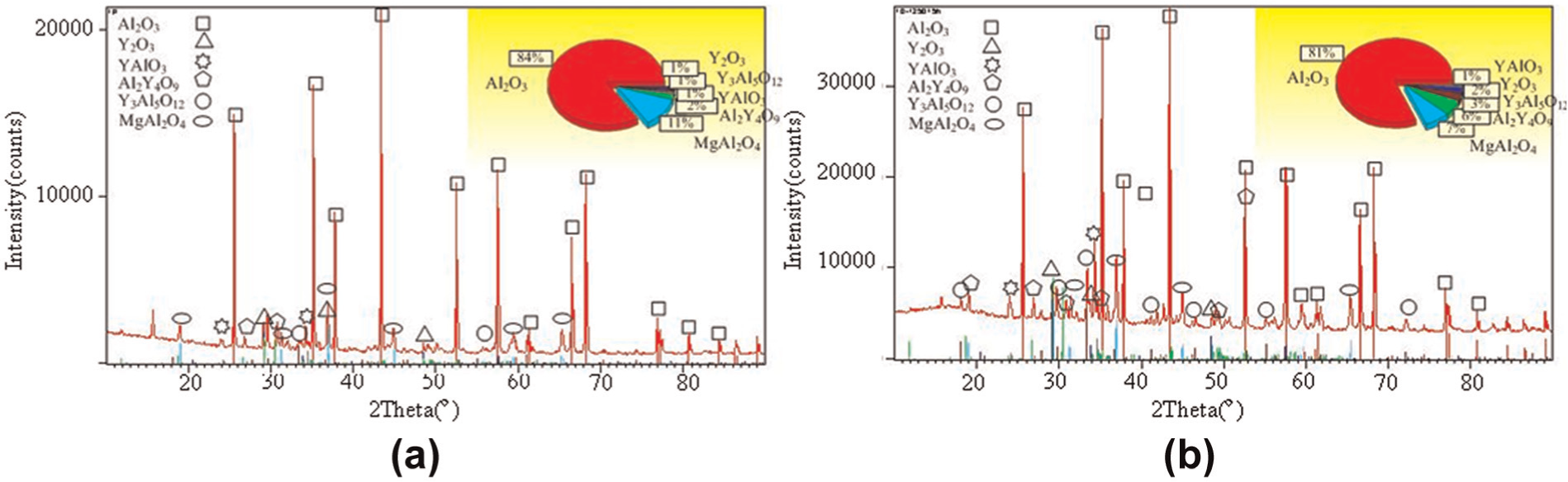
Phase compositions of sintered samples containing (a) micron-sized Y2O3 and (b) nano-sized Y2O3.
Casting of gas turbine blade
The CAD model of mold prototype was first designed, and the dimension between mold shell and mold core was set as 9 mm so that the thickness of Al2O3-based ceramic mold shell was guaranteed according to above analysis in section “Ceramic shell thickness.” Then the complex SL mold was filled with water-based ceramic slurry on the basis of gelcasting. Figure 9(a) shows the integral Al2O3-based ceramic mold prepared after freeze-drying, presintering, impregnating, and high-temperature sintering. Then vacuum casting was done after the outside surface of Al2O3-based ceramic mold was again coated with coarser zircon sand for further reinforcement, and the casting parameters were same as those in above ProCAST simulation. Finally, a gas turbine blade was successfully fabricated in Figure 9(b) after linear cutting of casting head, the exhaust side of which was perfect, and core shift took place remarkably during casting, as shown in Figure 9(c), when using No. 1 composite powders in Table 1.
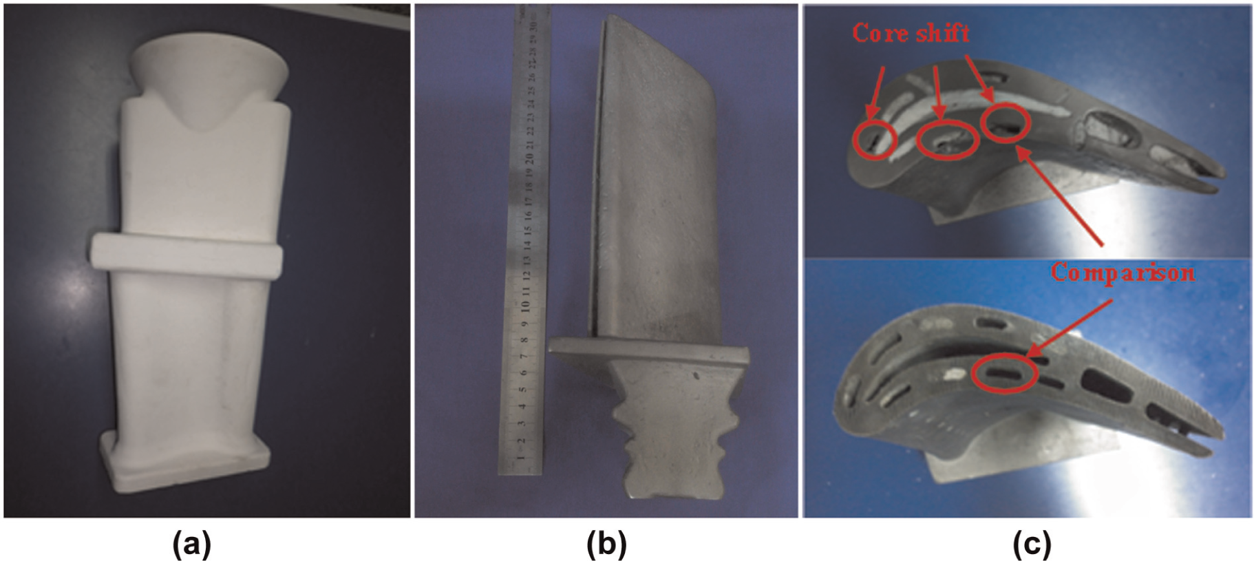
Integral ceramic mold and hollow turbine blade.
Conclusion
In this article, the cracking of Al2O3 ceramic mold results from the static pressure of liquid metal and the thermal stress during casting, but the thermal stress is the main factor.
The Al2O3 ceramic shell thickness has an important effect on thermal shock of liquid metal in the casting process, and the optimal 9 mm thickness of ceramic shell is put forward, which can decrease the critical thermal stress of ceramic shell to 8.7 MPa.
To increase the high-temperature flexure strength of Al2O3 ceramic shell, nano-Y2O3 (D50 = 20 nm) is added into Al2O3–MgO composite powders. After impregnating twice in yttrium sol, the high-temperature flexure strength of mold is strengthened to 13.1 MPa, which meets the requirement of vacuum casting of turbine blade.
Finally, a gas turbine blade is successfully fabricated. But the manufacturing precision of Al2O3 ceramic mold should be investigated in the future on the basis of the method of IFTCM.
Footnotes
Declaration of conflicting interests
The authors declare that there is no conflict of interest.
Funding
This study was supported by the Key Basic Research Projects (973) of China through Grant No. 2013 CB035703 and “the Fundamental Research Funds for the Central Universities.”