
Abstract
Micro-optical components made from polymethyl methacrylate are increasingly in demand. This article presents an experimental investigation into diamond micro-milling of polymethyl methacrylate components with nanometric surface roughness and its application perspectives. The experimental micro-milling trials with a chemical vapour deposition diamond ball endmill are conducted on a self-developed ultra-precision micro-milling machine (UltraMill) featuring high precision and high dynamic performance. Surface roughness of micro-milled slots using different micro-milling strategies is measured with white light interferometer. Results show that when feed and cutting orientations are perpendicular, smaller surface roughness can be obtained. Micro-milling is carried out on 2 × 2 mm2 areas by applying different micro-milling strategies and process parameters. The results demonstrate that the micro-milling strategy which can generate good surface roughness in slot micro-milling cannot produce expected surface roughness on such a large area (2 × 2 mm2), and machining dynamics plays an important role. By applying two-way joint micro-milling strategy and adjusting process parameters, an optical surface is obtained with roughness of 8.717 nm.
Keywords
Introduction
Nowadays, components for optical systems, which needs to be small, light, more powerful, faster and cost-efficient, are increasingly in demand. Micro-optics made of plastic materials can ideally suit these requirements and are widely used in instruments such as micro-electrical mechanical system (MEMS), lab-on-a-chip, bio-micro system and optical sensor system. 1 Polymethyl methacrylate (PMMA), due to its excellent properties and low cost, has become the main material for microlens in fields of optics display, optic imaging and communication.
Diamond micro-milling is a very suitable technique to machine small components and also to get mirror surface. Lots of research has been conducted on diamond milling metals such as copper and aluminium 2 –5 and successfully obtained surface roughness around 10 nm, but most of them just gave roughness data based on slots/grooves rather than areal surfaces. Research on diamond milling PMMA components is further limited. Sweatt et al. 6 reported on diamond milling micro-optics using a specially designed tool with roughness around 1 nm. McCall et al. 7 reported milling microlens arrays using ball nose single-crystalline diamond tool and obtained lens with roughness of 12–15 nm. Kirchberg et al. 8 combined single-crystalline diamond milling and injection moulding and got surface roughness at 25 nm. However, there is no systematic research on diamond milling PMMA towards nanometric surface roughness.
In this article, a chemical vapour deposition (CVD) tool is utilised to conduct well-designed micro-milling experiments on PMMA and to investigate the micro-milling strategies enabling optical surface. Machining methods and parameters are analysed and addressed in an optimal manner. Furthermore, the machining dynamics is also investigated particularly on the machining system to achieve nanometric level of surface roughness on PMMA components.
Challenges and fundamental issues in micro-milling PMMA components
There are some fundamental issues in micro-milling differentiating itself from conventional milling, which invalidate most of the principles in macroscopic machining. 9 In terms of cutting mechanism, size effect, which happens when the cutting parameters are comparable with tool geometry, is significant in micro-cutting; minimum chip thickness under which no chip will be formed places very important standard to choose cutting parameters. In terms of machine tool and machining dynamics, micro-milling of small components requires faster response time with minimum motion error and good stability and so on. To incorporate these considerations, a scientific approach to investigate micro-milling of PMMA component is illustrated in Figure 1, which is also applied as the guideline for undertaking consequent micro-milling trials.
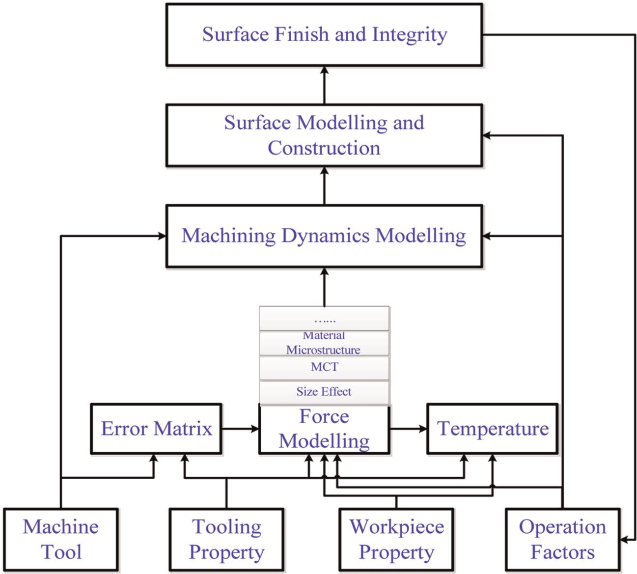
Scientific approach to micro-milling nanometric level of surface roughness.
Experimental investigation
Experimental setup
Machine tool
The five-axis ultra-precision micro-milling machine developed jointly by Brunel University and UPM Ltd possesses the capability to conduct ultra-precision micro-milling of various engineering materials. 10 It has three linear axes and two rotary axes, which offer the maximum flexibility to machine different structures as shown in Figure 2. Each linear axis has a resolution of 5 nm, while each rotary axis owns a resolution of 0.02 arsec. A universal motion and automation controller (UMAC) control system is adopted to guarantee the most accurate linear and rotary movement. All the axes are tuned to achieve linear motion accuracy of less than 1 µm over total travel range and rotary accuracy less than 1 arsec. A machining volume of 150 × 150 × 80 mm3 is specified to enable machining of large components. To meet the high rotational speed of micro-milling due to the shrinkage of cutting tools’ diameter, an ultra-high-speed air bearing spindle running up to 200,000 r/min is developed with radial and axial total indicated runout (TIR) less than 2 and 1 µm, respectively.
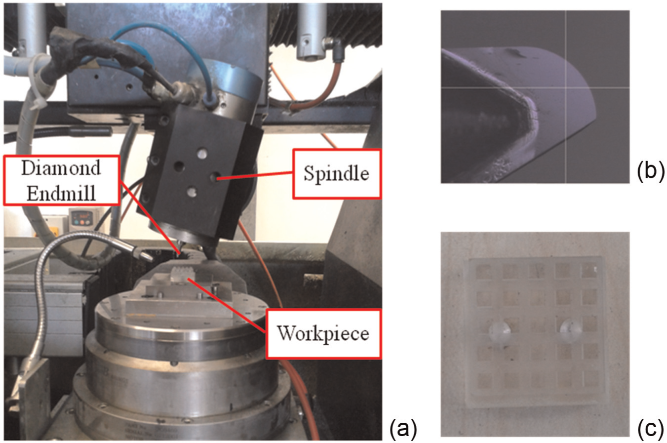
Experiment setup: (a) machine setup, (b) CVD tool and (c) machined workpiece.
Micro-milling tool
Normally, surface roughness obtained by tungsten carbide tools is around hundreds of nanometres. To achieve optical surface, a CVD diamond milling tool made by Contour Fine Tooling is utilised. CVD diamond tools, compared with natural diamond tools, can achieve similar machining quality in terms of accuracy and surface roughness and also have the advantage of being able to machine ferrous materials that cannot be processed by natural diamond tools. The utilised CVD diamond milling tool has one single flute and nominal diameter of 1.5 mm. There are few reports on CVD diamond micro-milling throughout the literature. Huo and Cheng 3 machined some slots employing CVD diamond milling tools on oxygen-free copper with the best surface roughness of 13 nm.
Experimental cutting trials
Two blocks of PMMA are prepared both of whose external dimensions are 20 × 20 × 10 mm3 with top surface at its initial state with a surface roughness of 7–10 nm. One is designed to conduct slot machining to decide the optimum cutting strategy. The second one is first machined into 2 × 2 × 1 mm3 upstands for multiple cutting trials. Both are mounted on a specially designed clamping system that minimises the levelness error against X–Y plane and aligned properly with machine coordinate system. The CVD diamond cutting tool clamped in the tool collet is adjusted properly to have a runout less than 5 µm.
Machining strategies
Climb-milling is recommended to obtain smaller surface roughness in conventional milling process. To investigate the scenario in micro-milling, four kinds of machining strategy are performed as shown in Figure 3. To avoid zero cutting speed that results in squeezing and rubbing substrate material, and consequently bad surface roughness, the tool is tilted at an angle of 15° throughout all the following cutting trials, whether lean angle or lead angle. The lean angle is the angle between vertical axis and tool axis in the plane, which is perpendicular to the feed rate direction, while the lead angle represents the angle in the plane in the feed rate direction and orthogonal to the workpiece surface. The rotational speed of the spindle is set to 36,000 r/min, and thus, the maximum cutting speed is 365 mm/s. The depth of cut (DOC) is kept constant at 50 µm. The feed rate, which is more concerned with machined surface roughness, is set to 2.7, 2 and 1 µm.
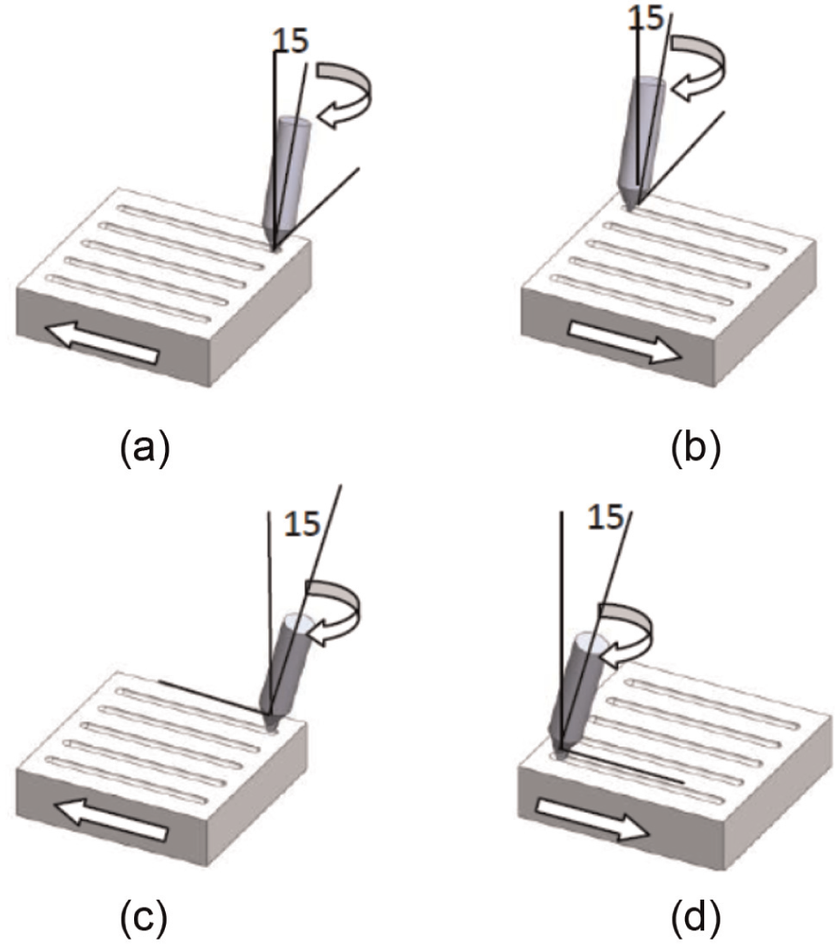
Four different machining strategies: (a) 15° lean angle, up-milling, (b) 15° lean angle, down-milling, (c) 15° lead angle, feed from left to right and (d) 15° lead angle, feed from right to left.
In Figure 3(a) and (b), the tool is tilted with a lean angle of 15°; Figure 3(a) resembles up-milling, in which cutting direction is contrary to feed direction, while Figure 3(b) resembles down-milling, in which cutting and feed directions are the same. In Figure 3(c) and (d), tool is tilted with a lead angle of 15°; Figure 3(c) represents feed direction pushing tool away from engagement, while Figure 3(d) displays feed direction pushing tool towards deeper engagement. Each slot is measured using a white light interferometer (Zygo NewView 5000) at five different locations to reduce uncertainty and assess repeatability. The averaged value is used as surface roughness.
Machining areal surface
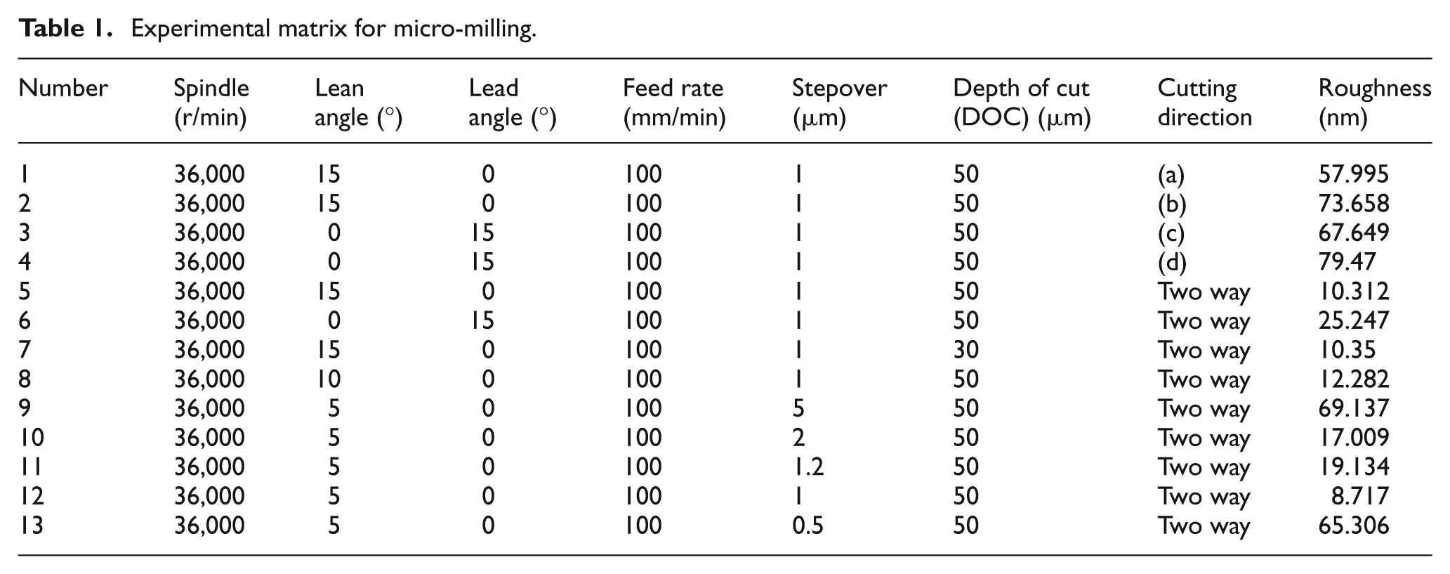
To investigate strategy for optical surface roughness and reveal the difference between slot machining and area machining, experiments are conducted with varying cutting parameters based on previously obtained experience and results mainly through varying stepover. The experimental matrix and measurement results are listed in Table 1.
Experimental matrix for micro-milling.
Results and discussion
Surface roughness in slot micro-milling
Surface roughness obtained in each slot is listed in Table 2. Better results are observed using (c) and (d) strategies. Considering the cutting geometry of different strategies, cutting direction at the tool tip in (a) and (b) is the same with feed rate, while cutting direction in (c) and (d) is perpendicular to feed rate. A zoom-in section of cutting process at the tool tip is displayed in Figure 4(a) and (b), so the machined surface in (a) and (b) is generated by the replication of the tool geometry, and the uneven wear of flank face is also replicated onto the generated surface. In (c) and (d), however, the machined surface is generated by the lowest point on the cutting edge; thus, even in the presence of tool wear on the flank face, a smooth surface could also be obtained. With decreased feed rate, the distance between two consecutive tool cuttings becomes smaller; the roughness is significantly improved in (c) and (d), while due to unevenness of flank face, roughness in (a) and (b) did not change a lot. A comparison of the cross-sectional profile of the slots (a) and (c) at feed rate of 100 mm/min is shown below. Cylinder form error is removed in both profiles. It shows that roughness of slot (c), 30.146 nm, is much better than that of slot (a), 130.671 nm, which proves the speculations mentioned above.
Machining parameters in slot micro-milling.
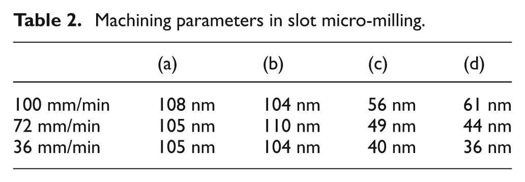
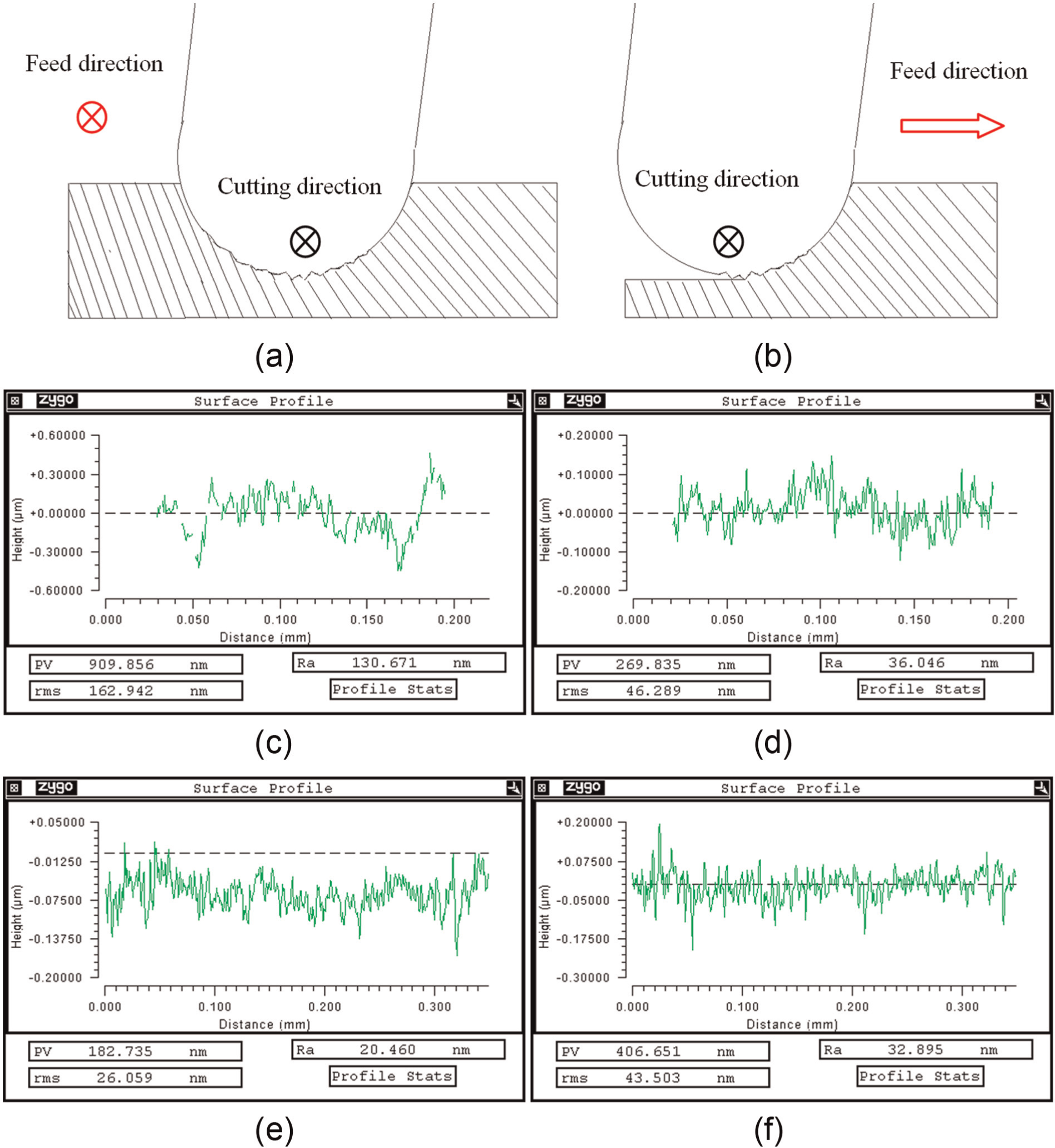
Difference between strategies with lean angle and lead angle: (a) cutting with lean angle, (b) cutting with lead angle, (c) cross section of slot with lean angle, (d) cross section of slot with lead angle, (e) bottom line of slot with lean angle and (f) bottom line of slot with lead angle.
However, the profile along the feed direction reveals other phenomenon. Profile of slots (b) and (d) at feed rate of 36 mm/min in the feed direction is shown in the following. Profile of slot (b), although more irregular, has a roughness of 20.46 nm. While profile of slot (d), regular due to fixed feed rate, has a roughness of 32.895 nm. This may indicate that when the slot is expanded perpendicular to the feed direction, a better surface roughness is more likely when adopting strategy (a) or (b).
Roughness observed in (d) is slightly better than that in (c); one explanation is that the force exerted onto the tool tip is pushing the tool away from the workpiece, which generates tool bounce at the cutting edge, while the force in (d) is trying to press the tool onto the workpiece, which leads to more stable cutting conditions. Due to the unevenness of the flank face, roughness observed in (a) and (b) does not change too much as shown by the result.
Surface roughness in areal micro-milling
With knowledge of results by different strategies, cutting trials are conducted on 2 × 2 mm2 surface as shown in Table 1. First, cutting trials are implemented by adopting four strategies separately. However, results are much worse than anticipated. Examining the surface profile, a regular sinusoidal pattern can be seen, as shown in Figure 5(a). The explanation could only be found by correlating this with dynamic machining process. The repetitive and frequent up–down movements of z-axis could cause slight variation at commanded position. Besides, air pressure variation could also result in fluctuation in z-axis, which leads to this particular pattern.
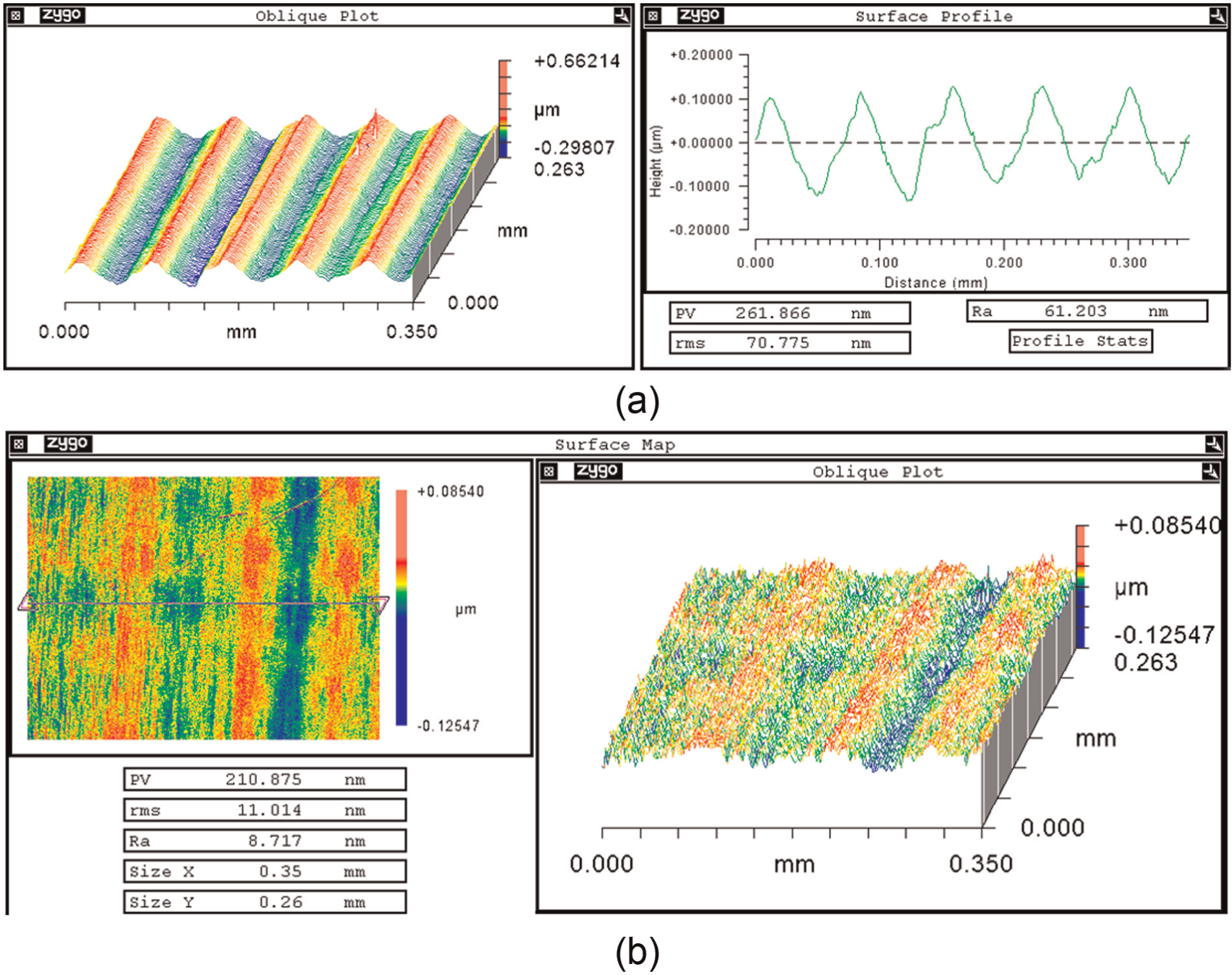
Machined surface with (a) regular pattern (climb-milling) and (b) nanometric roughness.
To eliminate the influence of up–down movement of z-axis, two-way (up- and down-milling) joint machining strategy is adopted with lean angle of 15°. The roughness is significantly reduced to 10.312 nm. Experiments 5 and 6 reveal that machining with lean angle can produce smaller surface roughness, compared to 10.312–25.247 nm obtained. This discovery is consistent with preceding discussion in section ‘Surface roughness in slot micro-milling’.
Through adjusting other parameters mainly varying stepover, different results are obtained. Results show that appropriate selection of stepover is the most predominant factor to get smaller surface roughness. Through varying stepover by 5, 2, 1.2, 1 and 0.5 µm, there exists an optimum stepover, which is around 1 µm. As the stepover increases from 1 µm, the distance between two adjacent tool passes is larger and the cusp height left behind becomes large, which results in bad surface roughness. While stepover is less than 1 µm, due to the minimum chip thickness effect, chip will not be formed during each tool pass; it accumulates until the minimum chip thickness is exceeded. It turns into cutting from rubbing and ploughing; the change of cutting mechanism could produce unpredictable tool vibration, which deteriorates surface roughness. Other parameters’ influence on surface roughness will be investigated further and should be closely associated with machining process dynamics.
The best surface roughness is obtained at parameters used in experiment 11. An optical surface with 8.717 nm surface roughness is obtained as illustrated in Figure 5(b).
Conclusion
A CVD diamond ball endmill has been used to micro-mill PMMA components with nanometric surface roughness. Through a series of micro-milling experiments, the following conclusions can be drawn.
Slot micro-milling experiments show that by feeding the tool in the same direction as cutting direction, in (c) and (d), a better surface roughness could be obtained. However, comparing the profile in the direction of feed rate, strategies (a) and (b) may produce smoother profiles.
When expanding the slot micro-milling to create big area (2 × 2 mm2), none of the four strategies is able to produce good results. By joining up- and down-milling together, optical surfaces could be generated with roughness around 10 nm.
The stepover is most dominant factor affecting the machined surface roughness mostly. A stepover of 1 µm per tool pass is able to generate surface roughness of 8.717 nm.
Future work should be focused on building a model to predict the surface roughness incorporating different micro-milling parameters. Furthermore, this model should be extended to other applications such as micro-milling copper, aluminium, titanium alloys and other typical engineering materials. Investigations on micro-milling of three-dimensional (3D) complex surfaces should also be conducted to test and validate the capability of the micro-milling strategies.
Footnotes
Declaration of conflicting interests
The authors declare that there is no conflict of interest.
Funding
The authors would like to thank the Korean Institute of Materials and Machinery (KIMM) for partially funding this research (grant No. R31063).